EP2582460B1 - Appareil concasseur de roches - Google Patents
Appareil concasseur de roches Download PDFInfo
- Publication number
- EP2582460B1 EP2582460B1 EP11796018.7A EP11796018A EP2582460B1 EP 2582460 B1 EP2582460 B1 EP 2582460B1 EP 11796018 A EP11796018 A EP 11796018A EP 2582460 B1 EP2582460 B1 EP 2582460B1
- Authority
- EP
- European Patent Office
- Prior art keywords
- crushing
- rotor
- rock
- compression
- crushing apparatus
- Prior art date
- Legal status (The legal status is an assumption and is not a legal conclusion. Google has not performed a legal analysis and makes no representation as to the accuracy of the status listed.)
- Not-in-force
Links
Images



Classifications
-
- B—PERFORMING OPERATIONS; TRANSPORTING
- B02—CRUSHING, PULVERISING, OR DISINTEGRATING; PREPARATORY TREATMENT OF GRAIN FOR MILLING
- B02C—CRUSHING, PULVERISING, OR DISINTEGRATING IN GENERAL; MILLING GRAIN
- B02C21/00—Disintegrating plant with or without drying of the material
-
- B—PERFORMING OPERATIONS; TRANSPORTING
- B02—CRUSHING, PULVERISING, OR DISINTEGRATING; PREPARATORY TREATMENT OF GRAIN FOR MILLING
- B02C—CRUSHING, PULVERISING, OR DISINTEGRATING IN GENERAL; MILLING GRAIN
- B02C13/00—Disintegrating by mills having rotary beater elements ; Hammer mills
- B02C13/14—Disintegrating by mills having rotary beater elements ; Hammer mills with vertical rotor shaft, e.g. combined with sifting devices
- B02C13/18—Disintegrating by mills having rotary beater elements ; Hammer mills with vertical rotor shaft, e.g. combined with sifting devices with beaters rigidly connected to the rotor
- B02C13/1807—Disintegrating by mills having rotary beater elements ; Hammer mills with vertical rotor shaft, e.g. combined with sifting devices with beaters rigidly connected to the rotor the material to be crushed being thrown against an anvil or impact plate
-
- B—PERFORMING OPERATIONS; TRANSPORTING
- B02—CRUSHING, PULVERISING, OR DISINTEGRATING; PREPARATORY TREATMENT OF GRAIN FOR MILLING
- B02C—CRUSHING, PULVERISING, OR DISINTEGRATING IN GENERAL; MILLING GRAIN
- B02C13/00—Disintegrating by mills having rotary beater elements ; Hammer mills
- B02C13/14—Disintegrating by mills having rotary beater elements ; Hammer mills with vertical rotor shaft, e.g. combined with sifting devices
- B02C13/18—Disintegrating by mills having rotary beater elements ; Hammer mills with vertical rotor shaft, e.g. combined with sifting devices with beaters rigidly connected to the rotor
- B02C13/1807—Disintegrating by mills having rotary beater elements ; Hammer mills with vertical rotor shaft, e.g. combined with sifting devices with beaters rigidly connected to the rotor the material to be crushed being thrown against an anvil or impact plate
- B02C13/1835—Disintegrating by mills having rotary beater elements ; Hammer mills with vertical rotor shaft, e.g. combined with sifting devices with beaters rigidly connected to the rotor the material to be crushed being thrown against an anvil or impact plate by means of beater or impeller elements fixed in between an upper and lower rotor disc
-
- B—PERFORMING OPERATIONS; TRANSPORTING
- B02—CRUSHING, PULVERISING, OR DISINTEGRATING; PREPARATORY TREATMENT OF GRAIN FOR MILLING
- B02C—CRUSHING, PULVERISING, OR DISINTEGRATING IN GENERAL; MILLING GRAIN
- B02C13/00—Disintegrating by mills having rotary beater elements ; Hammer mills
- B02C13/26—Details
- B02C13/28—Shape or construction of beater elements
-
- B—PERFORMING OPERATIONS; TRANSPORTING
- B02—CRUSHING, PULVERISING, OR DISINTEGRATING; PREPARATORY TREATMENT OF GRAIN FOR MILLING
- B02C—CRUSHING, PULVERISING, OR DISINTEGRATING IN GENERAL; MILLING GRAIN
- B02C13/00—Disintegrating by mills having rotary beater elements ; Hammer mills
- B02C13/26—Details
- B02C13/30—Driving mechanisms
Definitions
- This invention relates to a rock crushing apparatus. More particularly, this invention relates to a vertical shaft rock crushing apparatus using combined compression and impact crushing processes primarily for the production of high quality aggregates and also for other general rock crushing applications.
- rock crushing equipment that is used to reduce the size of high strength rock types has been manufactured in one of two different categories. These 'crushers' are categorised as either compression crushers or impact crushers. These two categories utilise two distinctly different processes to crush rock. Compression crushing physically loads rock particles between two metal surfaces, closing the gap between these surfaces during a crushing cycle and developing forces high enough to crack the trapped rock into multiple fragments. Impact crushing creates crushing forces via high velocity impacts of either metal on rock, rock on metal or rock on rock. Each method has its advantages and disadvantages. Compression crushing has the advantage of positive size reduction where the product size created is smaller than the feed size in a predetermined 'reduction ratio' which can be altered according to the 'setting' of the crushing apparatus.
- each crushing process it is often used in conjunction with each other, where a number of compression crushing apparatuses will be used to reduce the size of the material down to the general product size range and then an impact crushing apparatus is used for the final 'shaping' and other quality improvement of the product.
- Compression crushing apparatuses generally fall into two sub-categories: Jaw crushers, where the crushing surfaces are two flat plates; usually one moving and one stationary, and cone (or gyratory) crushers which utilise the layout of a gyrating cone within a stationary conical shell.
- Jaw crushers where the crushing surfaces are two flat plates; usually one moving and one stationary, and cone (or gyratory) crushers which utilise the layout of a gyrating cone within a stationary conical shell.
- the choice of compression crusher type for a particular application generally depends on the desired throughput vs. the feed size. Jaw crushing tends to be used in applications with a larger feed size at low to moderate production rates. Cone and gyratory crushing tends to be used in higher throughput applications where the feed size is smaller.
- Impact crushing apparatuses also generally fall into two sub-categories: those where the crushing impact is created by metal components hitting rock (or vice versa ), and those where the crushing impact is essentially rock hitting rock (so called 'autogenous' crushing).
- the choice of which type of impact crushing apparatus is used depends largely on the properties of the rock to be crushed. In abrasive rock types the autogenous crushing process is used almost exclusively, due to the uneconomic wear rates of metal components when they are subjected to high velocity, high abrasion impacts.
- the standard form of the autogenous impact crushing apparatus is that of a horizontal rotor, rotating on a vertical shaft, into which the rock to be crushed falls.
- a vertical shaft impactor or VSI
- the important design parameters of an autogenous VSI are; the feed opening, the rotor size and the rotation speed.
- the combination of rotor size and rotation speed determines the rim (or 'tip') speed of the rotor which governs the maximum level of kinetic energy available to the rock as it leaves the rotor. It is this available kinetic energy which largely controls the degree of size reduction achieved by the apparatus, and its power consumption, which is the dominant cost component in its operation.
- NZ 201190 , NZ 250027 , NZ 274265 , NZ 274266 , NZ 299299 , NZ 328061 , NZ 328062 and NZ 502725 disclose various tip designs to enable rock bed creation within the rotor, with the effect being to limit Vr to acceptable levels.
- autogenous VSI designers have been forced to limit input feed particle size dramatically to reduce coriolis force point loading and other tip impact loads. It is an object of the present invention to address the foregoing problems or at least to provide the public with a useful choice.
- International Patent Application Publication No. WO 2010/008273 relates to a sliding member that is pivotly attached along one side to an open rotor.
- German Patent Application Publication No. DE 10 2005 055620 relates to an apparatus for processing composite building materials to recover components comprises a rotor equipped with movable impact elements having an adjustable angle of attack.
- a rock crushing apparatus comprising:
- centrifugal and coriolis forces produced on feed material by the rotational motion of the rotor are utilised to assist the flow of material through the compression crushing elements, to reduce the power required to drive the compression crushing elements by minimising energy loss to internal friction and minimising rotor wear.
- the centrifugal force produced during high speed rotation of the rotor allows increased crushing capacity from small compression crushing elements.
- the compression crushing elements are jaw compression crushing elements.
- each compression crushing element also comprises a fixed portion.
- the fixed portion comprises a leading edge and a trailing edge with respect to the direction of rotation of the rotor.
- each compression crushing element also comprises an adjustment means for each crusher element to control the compression crushing element setting.
- the compression crushing elements are angled with respect to the direction of rotation of the rotor.
- the compression crushing elements are oriented so that they reciprocate in the same plane as the rotation of the rotor.
- the reciprocating means is located on a trailing side of each compression crushing element with respect to a direction of rotation of the rotor.
- the reciprocating portion is driven via a sub rotor.
- the reciprocating portion is driven in a reciprocal motion by direct contact with a surface surrounding and external to the rotor.
- each compression crushing element is orientated so that it is subjected to a reactive force from the rock flowing through the rotor to reduce the load on the compression crushing drive mechanism and thus improve the overall energy efficiency of the apparatus.
- each compression crushing element utilises a portion of the kinetic energy of the rock within the rotor. If the reciprocating portion is on the trailing side of the rotor as it rotates it is subjected to a coriolis force reaction; if the reciprocating portion is orientated so that a centrifugal force acts on it, it is subjected to a centrifugal force reaction.
- rock passing between a channel formed between adjacent fixed portion and reciprocating portion is compression crushed.
- the compression crushing elements are positioned in pairs diametrically opposed to the other pair member and timed to reciprocate identically to each other. In this way, rotor balance is maintained during operation of the rock crushing apparatus.
- each pair of compression crushing elements is timed differently from the others so as to even the loading on the compression crushing drive mechanism.
- the rotor is configured to allow it to perform its crushing action while being driven in either direction of rotation.
- the adjacent surface is a rock bed surrounding the rotor.
- the crushing apparatus also comprises a rotor drive taking power from an attached power source, to create rotational motion of the rotor up to the desired tip speed.
- the crushing apparatus also comprises a compression crushing drive mechanism, comprising:
- the power from the power supply means can be provided via either rotational or linear motion to the reciprocating means.
- the crushing apparatus also comprises an attaching means configured to attach the rotor to the rotor drive so that the rotor may be easily removed for maintenance.
- the rotor, rotor drive and compression crushing drive mechanism are configured so that the rock crushing apparatus performs identically when rotated in either direction.
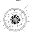
- a rock crushing apparatus is generally indicated by arrow (1) in Figures 5 and 6 .
- a rotor (2) is mounted on top of a sub rotor (3) via a mounting arrangement? (4) (best seen in Figure 4a ). Both the rotor (2) and sub rotor (3) are mounted on the main shaft (5) of the apparatus (1) and spin together at the same rotational speed.
- a compression crushing gear drive mechanism (6),(7),(8) within the sub rotor (3) ( Figure 4b ) which rotates the four couplings (9) (as shown in Figures 4a and 4b ) protruding from the top of the sub rotor (3) at an independent rotation speed.
- This (coupling) rotation speed is either a fixed multiple of the rotor (2) speed, adjusted in steps by the sub rotor (3) gear ratio used, or a completely independent variable speed, as described later.
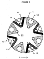
- the couplings (9) are engaged (in a predetermined manner) with the four eccentric shafts (10) (as shown in Figure 2 ) within the rotor (2) (as shown in Figure 2 ).
- Eccentric shafts (10) utilise bearings to efficiently create a reciprocating motion of a reciprocating means in the form of the compression crushing element (11) moving jaws about their pivot pins (22) in known fashion.
- Compression crushing elements also include fixed jaws (12), (13) against which rock particles passing through the compression crushing element (11) are crushed.
- the crushed rock is then released from the individual crushing elements (10)-(13) in diametrically opposed pairs at low radial velocity (Vr), and then thrown outwards to impinge on the adjacent surface (100) of the bed of rock (200) surrounding the rotor (2) (best seen in Figures 5 and 6 ).
- the subsequent impact with the rock bed (200) further crushes, shapes and improves the product rock in known fashion.
- the product rock then falls downwards (in the direction of arrows B in Figure 5 ) and out of the apparatus (1) to be conveyed away.
- the compression crushing elements (10)-(13) are periodically adjusted by an adjustment means in the form of pivoting the fixed jaws (12), (13) about their pivot pins (16) and placing appropriately sized adjustment links (17), (18) behind the jaws. These adjustments are performed through an inspection door in the apparatus body (not shown) in known fashion.
- an adjustment means in the form of pivoting the fixed jaws (12), (13) about their pivot pins (16) and placing appropriately sized adjustment links (17), (18) behind the jaws.
- the rock crushing apparatus (1) will perform identically when driven in either direction. So if power source (300) is of a type which is bi-directional (of which there are many examples) the apparatus can be run in one direction until the wear limits of the trailing fixed jaws (12) are approached and then the apparatus can be restarted in the opposite direction and reused until the leading fixed jaws (13) are at their wear limits.
- power source (300) is of a type which is bi-directional (of which there are many examples) the apparatus can be run in one direction until the wear limits of the trailing fixed jaws (12) are approached and then the apparatus can be restarted in the opposite direction and reused until the leading fixed jaws (13) are at their wear limits.
- the centrifugal force x increased radius component can be extracted by the moving component of the crushing element (11).
- a common power source or sources
- work extracted by one element (10)-(13) can be applied to assist the (crushing) motion of another element (10)-(13). So the process is essentially one where the rotor (2) performs work on the rock which simultaneously performs work 'back' on the crushing mechanism. This work done by the rock reduces the power required to drive the apparatus (1).
- the work extracted is due to the action of both centrifugal and coriolis forces and is maximised if the reciprocating component (11) is on the trailing side with respect to the direction of rotation of the rotor (2). Angling of the crushing elements (10)-(13) in the plane of rotation also improves the ratio of extracted work to frictional losses.
- Major design considerations are described below.
- the apparatus can be configured to allow quick removal of the rotor (2) and its replacement with a pre-serviced one, without disturbing the sub rotor (3) or rotor drive (5), (14). The worn rotor (2) can then be reconditioned for reuse while the apparatus is running with the replacement rotor (2) in known fashion.
- Compression crushing element (10)-(13) options also include (but are not limited to):
- Compression crushing elements (10)-(13) may be oriented perpendicularly, or at an angle to the direction of rotation and/or the plane of rotation.
- Compression crushing elements may also be mini cone crushers as known in the art.
- This second power source (400) can be used in one of three ways:
- the use of an arresting crushing process to limit the Vr attained by the feed rock to a relatively low value is advantageous for VSI rotor life. If the mechanism is one by which the energy available internally within the rotor (due to the rocks' travel from centre to rim) is applied efficiently to advantageous crushing processes its benefit is further maximised.
- the present invention is one by which both these objectives are achieved: Coriolis force rotor and tip abrasion is minimised while energy lost to internal friction is also minimised.
Landscapes
- Engineering & Computer Science (AREA)
- Food Science & Technology (AREA)
- Crushing And Grinding (AREA)
- Crushing And Pulverization Processes (AREA)
Claims (15)
- Appareil concasseur de roche (1) comprenant :
un rotor (2), caractérisé par :
un certain nombre d'éléments de concassage par compression (11, 12, 13) disposés sur une surface intérieure du rotor, le rotor comprenant aussi :
des moyens de mouvement alternatif (11) agencés pour créer un mouvement alternatif sur une portion à mouvement alternatif de chaque élément de concassage par compression pour concasser par compression la roche, et dans lequel la portion à mouvement alternatif réalise une action d'arrêt sur la roche fournie dans le rotor lorsqu'il tourne, limitant ainsi la vitesse radiale maximum (Vr) que la roche atteint dans le rotor avant son éjection à partir des éléments de concassage par compression pour un concassage par impact sur une surface adjacente. - Appareil concasseur de roche selon la revendication 1, dans lequel les éléments de concassage par compression sont des éléments de concassage par compression à mâchoires.
- Appareil concasseur de roche selon la revendication 1 ou 2, dans lequel chaque élément de concassage par compression comprend aussi une portion fixe (12, 13) ; dans lequel la portion fixe comprend un bord avant et un bord arrière par rapport à la direction de rotation du rotor ; et dans lequel la portion fixe de chaque élément de concassage par compression comprend aussi des moyens d'ajustement pour que chaque élément de concassage contrôle le réglage de l'élément de concassage par compression.
- Appareil concasseur de roche selon l'une quelconque des revendications 1 à 3, dans lequel les éléments de concassage par compression font un angle par rapport à la direction de rotation du rotor.
- Appareil concasseur de roche selon l'une quelconque des revendications 1 à 4, dans lequel la portion à mouvement alternatif (11) est située sur un côté arrière de chaque élément de concassage par compression par rapport à une direction de rotation du rotor.
- Appareil concasseur de roche selon l'une quelconque des revendications 1 à 5, dans lequel la portion à mouvement alternatif est entraînée par l'intermédiaire d'un sous-rotor (3).
- Appareil concasseur de roche selon l'une quelconque des revendications 1 à 6, dans lequel la portion à mouvement alternatif de chaque élément de concassage par compression fait un angle dans le plan de rotation du rotor de sorte qu'elle est soumise à une force de réaction provenant de la roche s'écoulant dans le rotor.
- Appareil concasseur de roche selon l'une quelconque des revendications 1 à 7, dans lequel il y a un nombre pair de portions à mouvement alternatif et de portions fixes également espacées autour d'une périphérie du rotor ; dans lequel de la roche passant dans un canal formé entre portion fixe et portion à mouvement alternatif adjacentes est concassée par compression.
- Appareil concasseur de roche selon l'une quelconque des revendications 1 à 8, dans lequel les éléments de concassage par compression sont disposés en paires diamétralement opposées entre les éléments de la paire et synchronisés pour aller et venir de façon identique entre eux, dans lequel l'action de concassage par compression de chaque paire d'éléments de concassage par compression est synchronisée différemment de chaque autre paire de façon à égaliser la charge sur le mécanisme d'entraînement de concassage par compression.
- Appareil concasseur de roche selon l'une quelconque des revendications 1 à 9, dans lequel le rotor est agencé pour lui permettre de réaliser son action de concassage par compression pendant qu'il est entraîné dans l'une ou l'autre des directions de rotation.
- Appareil concasseur de roche selon l'une quelconque des revendications 1 à 10, dans lequel la surface adjacente est un lit de roche (200) entourant le rotor.
- Appareil concasseur de roche selon l'une quelconque des revendications 1 à 11, dans lequel l'appareil concasseur comprend aussi un entraîneur de rotor prenant de l'énergie d'une source d'énergie attachée, pour créer un mouvement de rotation du rotor jusqu'à la vitesse de pointe souhaitée.
- Appareil concasseur de roche selon l'une quelconque des revendications 1 à 12, dans lequel l'appareil concasseur comprend aussi un mécanisme d'entraînement de concassage par compression, comprenant :des moyens de source d'énergie, agencés pour fournir de l'énergie aux moyens de mouvement alternatif, de sorte que le mouvement alternatif de chaque élément de concassage par compression peut être créé à une fréquence indépendante de la vitesse du rotor ; etun couplage pour permettre à l'entraîneur de rotor de prendre de l'énergie à partir du mécanisme d'entraînement de concassage par compression permettant à l'appareil concasseur d'être entraîné par une seule source d'énergie si nécessaire.
- Appareil concasseur de roche selon la revendication 12 ou 13, dans lequel l'appareil concasseur comprend aussi des moyens de fixation agencés pour fixer le rotor à l'entraîneur de rotor de sorte que le rotor peut être facilement retiré pour la maintenance.
- Appareil concasseur de roche selon la revendication 13 ou 14, dans lequel le rotor, l'entraîneur de rotor et le mécanisme d'entraînement de concasseur par compression sont agencés de telle sorte que l'appareil concasseur de roche se comporte de manière identique dans l'une ou l'autre des directions de rotation.
Applications Claiming Priority (2)
| Application Number | Priority Date | Filing Date | Title |
|---|---|---|---|
| NZ58628610A NZ586286A (en) | 2010-06-18 | 2010-06-18 | Combination compression and impactor rock crushing machine |
| PCT/NZ2011/000114 WO2011159175A1 (fr) | 2010-06-18 | 2011-06-20 | Appareil concasseur de roches |
Publications (3)
| Publication Number | Publication Date |
|---|---|
| EP2582460A1 EP2582460A1 (fr) | 2013-04-24 |
| EP2582460A4 EP2582460A4 (fr) | 2017-05-24 |
| EP2582460B1 true EP2582460B1 (fr) | 2018-10-03 |
Family
ID=45348389
Family Applications (1)
| Application Number | Title | Priority Date | Filing Date |
|---|---|---|---|
| EP11796018.7A Not-in-force EP2582460B1 (fr) | 2010-06-18 | 2011-06-20 | Appareil concasseur de roches |
Country Status (7)
| Country | Link |
|---|---|
| US (1) | US9126203B2 (fr) |
| EP (1) | EP2582460B1 (fr) |
| AU (1) | AU2011265839B2 (fr) |
| CA (1) | CA2803075C (fr) |
| NZ (1) | NZ586286A (fr) |
| WO (1) | WO2011159175A1 (fr) |
| ZA (1) | ZA201209607B (fr) |
Cited By (1)
| Publication number | Priority date | Publication date | Assignee | Title |
|---|---|---|---|---|
| CN112191329A (zh) * | 2019-09-19 | 2021-01-08 | 浙江芸洁科技有限公司 | 一种超低能耗的循环磨 |
Families Citing this family (3)
| Publication number | Priority date | Publication date | Assignee | Title |
|---|---|---|---|---|
| EP3749105A4 (fr) | 2019-04-11 | 2021-10-06 | Goli Nutrition Inc. | Complément nutritionnel au vinaigre de cidre de pomme |
| CN117282488B (zh) * | 2023-10-24 | 2025-09-12 | 浙江恒合瑞建设工程有限公司 | 一种市政道路修补用废弃石块破碎撞击装置及破碎方法 |
| CN120628979B (zh) * | 2025-06-27 | 2026-01-30 | 中国科学院武汉岩土力学研究所 | 基于压电阵列的岩石动态破碎残余动能测量装置及方法 |
Family Cites Families (19)
| Publication number | Priority date | Publication date | Assignee | Title |
|---|---|---|---|---|
| US2637359A (en) * | 1948-06-14 | 1953-05-05 | Hughes Alvin W | Meat chopping method and apparatus utilizing a centrifugally positioned knife within a rotating and foraminous basket |
| US2958473A (en) * | 1958-12-10 | 1960-11-01 | Massie Thomas | Rock crusher |
| US4061279A (en) * | 1976-03-01 | 1977-12-06 | Pennsylvania Crusher Corporation | High-speed rotating crushing machinery |
| US4504020A (en) * | 1981-06-20 | 1985-03-12 | Kawasaki Jukogyo Kabushiki Kaisha | Pulverizing mill apparatus |
| NZ201190A (en) * | 1982-08-07 | 1986-07-11 | Barmac Ass Ltd | Additional wear tip for rotary mineral breaker |
| DE3721961C1 (de) * | 1987-07-03 | 1988-11-17 | Thyssen Industrie | Kappe fuer die allseitige UEberdeckung der Enden der Tragkoerper eines Hammerbrecherrotors |
| US5381974A (en) * | 1992-03-25 | 1995-01-17 | Gygi; Martin H. | Crusher |
| GB9303749D0 (en) * | 1993-02-24 | 1993-04-14 | Baumung R Ind Ltd | Crushing apparatus |
| NZ274265A (en) * | 1993-10-14 | 1996-12-20 | Svedala Nz Ltd Formerly Tidco | Centrifugal mineral breaker in which the rotor assembly has at least one inset on the surface of its top or bottom plate |
| NZ274266A (en) * | 1993-10-14 | 1997-06-24 | Svedala Nz Ltd Formerly Tidco | Centrifugal mineral breaker with tip assembly attached to rotor using key |
| NZ250027A (en) * | 1993-10-22 | 1996-10-28 | Barmac Ass Ltd | Mineral breaker; scalloped wear tip |
| NZ299299A (en) * | 1996-09-04 | 1999-03-29 | Svedala Barmac Ltd Substituted | Rock breaker of type accumulating bed on rotor, having wear resistant tips repositionable radially and axially |
| NZ328062A (en) * | 1997-06-11 | 1999-10-28 | Svedala Barmac Ltd | Rotary mineral breakers having a contoured bed and weir |
| NZ328061A (en) * | 1997-06-11 | 1998-11-25 | Svedala Barmac Ltd | Rotary mineral crusher with focused output of the rotor includes a tip component engageable via a holder to define a transverse weir that is not symmetrical in a plane transverse to the radial direction |
| EP1084751A1 (fr) * | 1999-09-20 | 2001-03-21 | Van der Zanden, Johannes Petrus Andreas Josephus | Procédé et dispositif de broyage par collision synchronisée et symmétrique |
| NZ502725A (en) * | 2000-02-07 | 2002-10-25 | Svedala Barmac Ltd | Rotary mineral breaker of autogenous type with contoured backing region leading to exit port on rotor |
| FI20050538A0 (fi) * | 2005-05-20 | 2005-05-20 | Fractivator Oy | Voimansiirtolaitteisto |
| DE102005055620B4 (de) * | 2005-11-22 | 2019-01-31 | Proactor Schutzrechtsverwaltungs Gmbh | Vorrichtung zum Verarbeiten von Bauteilen aus Stoffgemischen |
| EP2328684A1 (fr) * | 2008-07-15 | 2011-06-08 | Van Der Zanden, Johannes, P. A. J. | Élément coulissant qui est fixé de façon pivotante le long d'un côté à un rotor ouvert |
-
2010
- 2010-06-18 NZ NZ58628610A patent/NZ586286A/xx unknown
-
2011
- 2011-06-20 CA CA2803075A patent/CA2803075C/fr active Active
- 2011-06-20 WO PCT/NZ2011/000114 patent/WO2011159175A1/fr not_active Ceased
- 2011-06-20 AU AU2011265839A patent/AU2011265839B2/en not_active Ceased
- 2011-06-20 US US13/704,967 patent/US9126203B2/en active Active
- 2011-06-20 EP EP11796018.7A patent/EP2582460B1/fr not_active Not-in-force
-
2012
- 2012-12-19 ZA ZA2012/09607A patent/ZA201209607B/en unknown
Non-Patent Citations (1)
| Title |
|---|
| None * |
Cited By (1)
| Publication number | Priority date | Publication date | Assignee | Title |
|---|---|---|---|---|
| CN112191329A (zh) * | 2019-09-19 | 2021-01-08 | 浙江芸洁科技有限公司 | 一种超低能耗的循环磨 |
Also Published As
| Publication number | Publication date |
|---|---|
| WO2011159175A1 (fr) | 2011-12-22 |
| CA2803075A1 (fr) | 2011-12-22 |
| EP2582460A4 (fr) | 2017-05-24 |
| US20130092772A1 (en) | 2013-04-18 |
| EP2582460A1 (fr) | 2013-04-24 |
| CA2803075C (fr) | 2019-05-14 |
| ZA201209607B (en) | 2013-08-28 |
| NZ586286A (en) | 2013-01-25 |
| US9126203B2 (en) | 2015-09-08 |
| AU2011265839A1 (en) | 2013-01-10 |
| AU2011265839B2 (en) | 2015-11-26 |
Similar Documents
| Publication | Publication Date | Title |
|---|---|---|
| CN105536957B (zh) | 一种叶轮及超细粉磨机、超细粉磨系统 | |
| US20120325949A1 (en) | Device for mechanical separation of material conglomerates from materials of different density and/or consistency | |
| JP4472703B2 (ja) | 粉砕装置 | |
| CN1455702A (zh) | 改进的二、三级可逆和不可逆锤式粉碎机 | |
| CA2803075C (fr) | Appareil concasseur de roches | |
| CN103657825A (zh) | 辊压机打散装置 | |
| CN106000544A (zh) | 连续进行冲击破碎和打击破碎的破碎方法 | |
| AU756149B2 (en) | Improvements to rock crushers | |
| KR102304913B1 (ko) | 폐타이어 고순도 철심분리장치 | |
| EP2319624B1 (fr) | Procédé de concassage fin de matériau en morceaux et dispositif de sa mise en oeuvre | |
| CN205925915U (zh) | 双转子单立轴破碎机 | |
| CN107716059A (zh) | 一种冲击式立轴破碎机 | |
| CN107670812A (zh) | 一种双转子立轴破碎机 | |
| CN208661289U (zh) | 一种自磨机及其耐磨型离心磨盘 | |
| RU2386480C2 (ru) | Вихревой измельчитель для каскадного измельчения | |
| WO2009154582A1 (fr) | Turbobroyeur vertical | |
| CN202962551U (zh) | 反击式破碎机 | |
| CN120815603B (zh) | 一种智能化高效锤式破碎装置及破碎方法 | |
| US20060138264A1 (en) | Mill with eccentric rotor | |
| CN2460204Y (zh) | 组合式微粉磨机 | |
| Kesavan | Size reduction | |
| JP2594829B2 (ja) | 遠心流動粉砕装置 | |
| CN2327445Y (zh) | 一种立式离心自磨机粉碎腔的新结构 | |
| SU957956A1 (ru) | Измельчитель конструкции Пологовича А.И. | |
| US20200188926A1 (en) | Methods and devices for continuous disintegration, drying and separation of bulk materials |
Legal Events
| Date | Code | Title | Description |
|---|---|---|---|
| PUAI | Public reference made under article 153(3) epc to a published international application that has entered the european phase |
Free format text: ORIGINAL CODE: 0009012 |
|
| 17P | Request for examination filed |
Effective date: 20121218 |
|
| AK | Designated contracting states |
Kind code of ref document: A1 Designated state(s): AL AT BE BG CH CY CZ DE DK EE ES FI FR GB GR HR HU IE IS IT LI LT LU LV MC MK MT NL NO PL PT RO RS SE SI SK SM TR |
|
| DAX | Request for extension of the european patent (deleted) | ||
| RA4 | Supplementary search report drawn up and despatched (corrected) |
Effective date: 20170425 |
|
| RIC1 | Information provided on ipc code assigned before grant |
Ipc: B02C 13/30 20060101ALI20170419BHEP Ipc: B02C 13/28 20060101ALI20170419BHEP Ipc: B02C 13/18 20060101AFI20170419BHEP |
|
| REG | Reference to a national code |
Ref country code: DE Ref legal event code: R079 Ref document number: 602011052598 Country of ref document: DE Free format text: PREVIOUS MAIN CLASS: B02C0025000000 Ipc: B02C0013180000 |
|
| GRAP | Despatch of communication of intention to grant a patent |
Free format text: ORIGINAL CODE: EPIDOSNIGR1 |
|
| STAA | Information on the status of an ep patent application or granted ep patent |
Free format text: STATUS: GRANT OF PATENT IS INTENDED |
|
| RIC1 | Information provided on ipc code assigned before grant |
Ipc: B02C 13/28 20060101ALI20180329BHEP Ipc: B02C 13/30 20060101ALI20180329BHEP Ipc: B02C 13/18 20060101AFI20180329BHEP |
|
| INTG | Intention to grant announced |
Effective date: 20180424 |
|
| GRAS | Grant fee paid |
Free format text: ORIGINAL CODE: EPIDOSNIGR3 |
|
| GRAA | (expected) grant |
Free format text: ORIGINAL CODE: 0009210 |
|
| STAA | Information on the status of an ep patent application or granted ep patent |
Free format text: STATUS: THE PATENT HAS BEEN GRANTED |
|
| AK | Designated contracting states |
Kind code of ref document: B1 Designated state(s): AL AT BE BG CH CY CZ DE DK EE ES FI FR GB GR HR HU IE IS IT LI LT LU LV MC MK MT NL NO PL PT RO RS SE SI SK SM TR |
|
| REG | Reference to a national code |
Ref country code: GB Ref legal event code: FG4D |
|
| REG | Reference to a national code |
Ref country code: CH Ref legal event code: EP Ref country code: AT Ref legal event code: REF Ref document number: 1048039 Country of ref document: AT Kind code of ref document: T Effective date: 20181015 |
|
| REG | Reference to a national code |
Ref country code: IE Ref legal event code: FG4D Ref country code: DE Ref legal event code: R096 Ref document number: 602011052598 Country of ref document: DE |
|
| REG | Reference to a national code |
Ref country code: SE Ref legal event code: TRGR |
|
| REG | Reference to a national code |
Ref country code: NL Ref legal event code: MP Effective date: 20181003 |
|
| REG | Reference to a national code |
Ref country code: LT Ref legal event code: MG4D |
|
| REG | Reference to a national code |
Ref country code: AT Ref legal event code: MK05 Ref document number: 1048039 Country of ref document: AT Kind code of ref document: T Effective date: 20181003 |
|
| PG25 | Lapsed in a contracting state [announced via postgrant information from national office to epo] |
Ref country code: NL Free format text: LAPSE BECAUSE OF FAILURE TO SUBMIT A TRANSLATION OF THE DESCRIPTION OR TO PAY THE FEE WITHIN THE PRESCRIBED TIME-LIMIT Effective date: 20181003 |
|
| PG25 | Lapsed in a contracting state [announced via postgrant information from national office to epo] |
Ref country code: BG Free format text: LAPSE BECAUSE OF FAILURE TO SUBMIT A TRANSLATION OF THE DESCRIPTION OR TO PAY THE FEE WITHIN THE PRESCRIBED TIME-LIMIT Effective date: 20190103 Ref country code: IS Free format text: LAPSE BECAUSE OF FAILURE TO SUBMIT A TRANSLATION OF THE DESCRIPTION OR TO PAY THE FEE WITHIN THE PRESCRIBED TIME-LIMIT Effective date: 20190203 Ref country code: NO Free format text: LAPSE BECAUSE OF FAILURE TO SUBMIT A TRANSLATION OF THE DESCRIPTION OR TO PAY THE FEE WITHIN THE PRESCRIBED TIME-LIMIT Effective date: 20190103 Ref country code: HR Free format text: LAPSE BECAUSE OF FAILURE TO SUBMIT A TRANSLATION OF THE DESCRIPTION OR TO PAY THE FEE WITHIN THE PRESCRIBED TIME-LIMIT Effective date: 20181003 Ref country code: CZ Free format text: LAPSE BECAUSE OF FAILURE TO SUBMIT A TRANSLATION OF THE DESCRIPTION OR TO PAY THE FEE WITHIN THE PRESCRIBED TIME-LIMIT Effective date: 20181003 Ref country code: PL Free format text: LAPSE BECAUSE OF FAILURE TO SUBMIT A TRANSLATION OF THE DESCRIPTION OR TO PAY THE FEE WITHIN THE PRESCRIBED TIME-LIMIT Effective date: 20181003 Ref country code: LT Free format text: LAPSE BECAUSE OF FAILURE TO SUBMIT A TRANSLATION OF THE DESCRIPTION OR TO PAY THE FEE WITHIN THE PRESCRIBED TIME-LIMIT Effective date: 20181003 Ref country code: ES Free format text: LAPSE BECAUSE OF FAILURE TO SUBMIT A TRANSLATION OF THE DESCRIPTION OR TO PAY THE FEE WITHIN THE PRESCRIBED TIME-LIMIT Effective date: 20181003 Ref country code: LV Free format text: LAPSE BECAUSE OF FAILURE TO SUBMIT A TRANSLATION OF THE DESCRIPTION OR TO PAY THE FEE WITHIN THE PRESCRIBED TIME-LIMIT Effective date: 20181003 Ref country code: AT Free format text: LAPSE BECAUSE OF FAILURE TO SUBMIT A TRANSLATION OF THE DESCRIPTION OR TO PAY THE FEE WITHIN THE PRESCRIBED TIME-LIMIT Effective date: 20181003 |
|
| PG25 | Lapsed in a contracting state [announced via postgrant information from national office to epo] |
Ref country code: AL Free format text: LAPSE BECAUSE OF FAILURE TO SUBMIT A TRANSLATION OF THE DESCRIPTION OR TO PAY THE FEE WITHIN THE PRESCRIBED TIME-LIMIT Effective date: 20181003 Ref country code: RS Free format text: LAPSE BECAUSE OF FAILURE TO SUBMIT A TRANSLATION OF THE DESCRIPTION OR TO PAY THE FEE WITHIN THE PRESCRIBED TIME-LIMIT Effective date: 20181003 Ref country code: GR Free format text: LAPSE BECAUSE OF FAILURE TO SUBMIT A TRANSLATION OF THE DESCRIPTION OR TO PAY THE FEE WITHIN THE PRESCRIBED TIME-LIMIT Effective date: 20190104 Ref country code: PT Free format text: LAPSE BECAUSE OF FAILURE TO SUBMIT A TRANSLATION OF THE DESCRIPTION OR TO PAY THE FEE WITHIN THE PRESCRIBED TIME-LIMIT Effective date: 20190203 |
|
| REG | Reference to a national code |
Ref country code: DE Ref legal event code: R097 Ref document number: 602011052598 Country of ref document: DE |
|
| PG25 | Lapsed in a contracting state [announced via postgrant information from national office to epo] |
Ref country code: DK Free format text: LAPSE BECAUSE OF FAILURE TO SUBMIT A TRANSLATION OF THE DESCRIPTION OR TO PAY THE FEE WITHIN THE PRESCRIBED TIME-LIMIT Effective date: 20181003 |
|
| PLBE | No opposition filed within time limit |
Free format text: ORIGINAL CODE: 0009261 |
|
| STAA | Information on the status of an ep patent application or granted ep patent |
Free format text: STATUS: NO OPPOSITION FILED WITHIN TIME LIMIT |
|
| PG25 | Lapsed in a contracting state [announced via postgrant information from national office to epo] |
Ref country code: RO Free format text: LAPSE BECAUSE OF FAILURE TO SUBMIT A TRANSLATION OF THE DESCRIPTION OR TO PAY THE FEE WITHIN THE PRESCRIBED TIME-LIMIT Effective date: 20181003 Ref country code: SK Free format text: LAPSE BECAUSE OF FAILURE TO SUBMIT A TRANSLATION OF THE DESCRIPTION OR TO PAY THE FEE WITHIN THE PRESCRIBED TIME-LIMIT Effective date: 20181003 Ref country code: SM Free format text: LAPSE BECAUSE OF FAILURE TO SUBMIT A TRANSLATION OF THE DESCRIPTION OR TO PAY THE FEE WITHIN THE PRESCRIBED TIME-LIMIT Effective date: 20181003 Ref country code: EE Free format text: LAPSE BECAUSE OF FAILURE TO SUBMIT A TRANSLATION OF THE DESCRIPTION OR TO PAY THE FEE WITHIN THE PRESCRIBED TIME-LIMIT Effective date: 20181003 |
|
| 26N | No opposition filed |
Effective date: 20190704 |
|
| PG25 | Lapsed in a contracting state [announced via postgrant information from national office to epo] |
Ref country code: SI Free format text: LAPSE BECAUSE OF FAILURE TO SUBMIT A TRANSLATION OF THE DESCRIPTION OR TO PAY THE FEE WITHIN THE PRESCRIBED TIME-LIMIT Effective date: 20181003 |
|
| PG25 | Lapsed in a contracting state [announced via postgrant information from national office to epo] |
Ref country code: MC Free format text: LAPSE BECAUSE OF FAILURE TO SUBMIT A TRANSLATION OF THE DESCRIPTION OR TO PAY THE FEE WITHIN THE PRESCRIBED TIME-LIMIT Effective date: 20181003 |
|
| REG | Reference to a national code |
Ref country code: CH Ref legal event code: PL |
|
| REG | Reference to a national code |
Ref country code: BE Ref legal event code: MM Effective date: 20190630 |
|
| PG25 | Lapsed in a contracting state [announced via postgrant information from national office to epo] |
Ref country code: TR Free format text: LAPSE BECAUSE OF FAILURE TO SUBMIT A TRANSLATION OF THE DESCRIPTION OR TO PAY THE FEE WITHIN THE PRESCRIBED TIME-LIMIT Effective date: 20181003 |
|
| PG25 | Lapsed in a contracting state [announced via postgrant information from national office to epo] |
Ref country code: IE Free format text: LAPSE BECAUSE OF NON-PAYMENT OF DUE FEES Effective date: 20190620 |
|
| PG25 | Lapsed in a contracting state [announced via postgrant information from national office to epo] |
Ref country code: LI Free format text: LAPSE BECAUSE OF NON-PAYMENT OF DUE FEES Effective date: 20190630 Ref country code: CH Free format text: LAPSE BECAUSE OF NON-PAYMENT OF DUE FEES Effective date: 20190630 Ref country code: LU Free format text: LAPSE BECAUSE OF NON-PAYMENT OF DUE FEES Effective date: 20190620 Ref country code: BE Free format text: LAPSE BECAUSE OF NON-PAYMENT OF DUE FEES Effective date: 20190630 |
|
| PG25 | Lapsed in a contracting state [announced via postgrant information from national office to epo] |
Ref country code: CY Free format text: LAPSE BECAUSE OF FAILURE TO SUBMIT A TRANSLATION OF THE DESCRIPTION OR TO PAY THE FEE WITHIN THE PRESCRIBED TIME-LIMIT Effective date: 20181003 |
|
| PG25 | Lapsed in a contracting state [announced via postgrant information from national office to epo] |
Ref country code: MT Free format text: LAPSE BECAUSE OF FAILURE TO SUBMIT A TRANSLATION OF THE DESCRIPTION OR TO PAY THE FEE WITHIN THE PRESCRIBED TIME-LIMIT Effective date: 20181003 Ref country code: HU Free format text: LAPSE BECAUSE OF FAILURE TO SUBMIT A TRANSLATION OF THE DESCRIPTION OR TO PAY THE FEE WITHIN THE PRESCRIBED TIME-LIMIT; INVALID AB INITIO Effective date: 20110620 |
|
| REG | Reference to a national code |
Ref country code: GB Ref legal event code: 732E Free format text: REGISTERED BETWEEN 20220113 AND 20220119 |
|
| PG25 | Lapsed in a contracting state [announced via postgrant information from national office to epo] |
Ref country code: MK Free format text: LAPSE BECAUSE OF FAILURE TO SUBMIT A TRANSLATION OF THE DESCRIPTION OR TO PAY THE FEE WITHIN THE PRESCRIBED TIME-LIMIT Effective date: 20181003 |
|
| PGFP | Annual fee paid to national office [announced via postgrant information from national office to epo] |
Ref country code: GB Payment date: 20240607 Year of fee payment: 14 |
|
| PGFP | Annual fee paid to national office [announced via postgrant information from national office to epo] |
Ref country code: DE Payment date: 20240607 Year of fee payment: 14 |
|
| PGFP | Annual fee paid to national office [announced via postgrant information from national office to epo] |
Ref country code: FR Payment date: 20240607 Year of fee payment: 14 Ref country code: FI Payment date: 20240618 Year of fee payment: 14 |
|
| PGFP | Annual fee paid to national office [announced via postgrant information from national office to epo] |
Ref country code: SE Payment date: 20240607 Year of fee payment: 14 |
|
| PGFP | Annual fee paid to national office [announced via postgrant information from national office to epo] |
Ref country code: IT Payment date: 20240618 Year of fee payment: 14 |
|
| REG | Reference to a national code |
Ref country code: DE Ref legal event code: R119 Ref document number: 602011052598 Country of ref document: DE |
|
| PG25 | Lapsed in a contracting state [announced via postgrant information from national office to epo] |
Ref country code: FI Free format text: LAPSE BECAUSE OF NON-PAYMENT OF DUE FEES Effective date: 20250620 |
|
| REG | Reference to a national code |
Ref country code: SE Ref legal event code: EUG |
|
| GBPC | Gb: european patent ceased through non-payment of renewal fee |
Effective date: 20250620 |
|
| PG25 | Lapsed in a contracting state [announced via postgrant information from national office to epo] |
Ref country code: GB Free format text: LAPSE BECAUSE OF NON-PAYMENT OF DUE FEES Effective date: 20250620 |
|
| PG25 | Lapsed in a contracting state [announced via postgrant information from national office to epo] |
Ref country code: DE Free format text: LAPSE BECAUSE OF NON-PAYMENT OF DUE FEES Effective date: 20260101 |
|
| PG25 | Lapsed in a contracting state [announced via postgrant information from national office to epo] |
Ref country code: IT Free format text: LAPSE BECAUSE OF NON-PAYMENT OF DUE FEES Effective date: 20250620 |
|
| PG25 | Lapsed in a contracting state [announced via postgrant information from national office to epo] |
Ref country code: FR Free format text: LAPSE BECAUSE OF NON-PAYMENT OF DUE FEES Effective date: 20250630 |