EP2582561B1 - Procédé et dispositif de réglage d'un frein à actionnement électrique et système de freinage électronique - Google Patents
Procédé et dispositif de réglage d'un frein à actionnement électrique et système de freinage électronique Download PDFInfo
- Publication number
- EP2582561B1 EP2582561B1 EP11721018.7A EP11721018A EP2582561B1 EP 2582561 B1 EP2582561 B1 EP 2582561B1 EP 11721018 A EP11721018 A EP 11721018A EP 2582561 B1 EP2582561 B1 EP 2582561B1
- Authority
- EP
- European Patent Office
- Prior art keywords
- actuator
- controller
- soll
- ist
- controller structure
- Prior art date
- Legal status (The legal status is an assumption and is not a legal conclusion. Google has not performed a legal analysis and makes no representation as to the accuracy of the status listed.)
- Active
Links
Images


Classifications
-
- B—PERFORMING OPERATIONS; TRANSPORTING
- B60—VEHICLES IN GENERAL
- B60T—VEHICLE BRAKE CONTROL SYSTEMS OR PARTS THEREOF; BRAKE CONTROL SYSTEMS OR PARTS THEREOF, IN GENERAL; ARRANGEMENT OF BRAKING ELEMENTS ON VEHICLES IN GENERAL; PORTABLE DEVICES FOR PREVENTING UNWANTED MOVEMENT OF VEHICLES; VEHICLE MODIFICATIONS TO FACILITATE COOLING OF BRAKES
- B60T8/00—Arrangements for adjusting wheel-braking force to meet varying vehicular or ground-surface conditions, e.g. limiting or varying distribution of braking force
- B60T8/17—Using electrical or electronic regulation means to control braking
-
- B—PERFORMING OPERATIONS; TRANSPORTING
- B60—VEHICLES IN GENERAL
- B60T—VEHICLE BRAKE CONTROL SYSTEMS OR PARTS THEREOF; BRAKE CONTROL SYSTEMS OR PARTS THEREOF, IN GENERAL; ARRANGEMENT OF BRAKING ELEMENTS ON VEHICLES IN GENERAL; PORTABLE DEVICES FOR PREVENTING UNWANTED MOVEMENT OF VEHICLES; VEHICLE MODIFICATIONS TO FACILITATE COOLING OF BRAKES
- B60T7/00—Brake-action initiating means
- B60T7/12—Brake-action initiating means for automatic initiation; for initiation not subject to will of driver or passenger
-
- B—PERFORMING OPERATIONS; TRANSPORTING
- B60—VEHICLES IN GENERAL
- B60T—VEHICLE BRAKE CONTROL SYSTEMS OR PARTS THEREOF; BRAKE CONTROL SYSTEMS OR PARTS THEREOF, IN GENERAL; ARRANGEMENT OF BRAKING ELEMENTS ON VEHICLES IN GENERAL; PORTABLE DEVICES FOR PREVENTING UNWANTED MOVEMENT OF VEHICLES; VEHICLE MODIFICATIONS TO FACILITATE COOLING OF BRAKES
- B60T13/00—Transmitting braking action from initiating means to ultimate brake actuator with power assistance or drive; Brake systems incorporating such transmitting means, e.g. air-pressure brake systems
- B60T13/74—Transmitting braking action from initiating means to ultimate brake actuator with power assistance or drive; Brake systems incorporating such transmitting means, e.g. air-pressure brake systems with electrical assistance or drive
- B60T13/741—Transmitting braking action from initiating means to ultimate brake actuator with power assistance or drive; Brake systems incorporating such transmitting means, e.g. air-pressure brake systems with electrical assistance or drive acting on an ultimate actuator
-
- B—PERFORMING OPERATIONS; TRANSPORTING
- B60—VEHICLES IN GENERAL
- B60T—VEHICLE BRAKE CONTROL SYSTEMS OR PARTS THEREOF; BRAKE CONTROL SYSTEMS OR PARTS THEREOF, IN GENERAL; ARRANGEMENT OF BRAKING ELEMENTS ON VEHICLES IN GENERAL; PORTABLE DEVICES FOR PREVENTING UNWANTED MOVEMENT OF VEHICLES; VEHICLE MODIFICATIONS TO FACILITATE COOLING OF BRAKES
- B60T8/00—Arrangements for adjusting wheel-braking force to meet varying vehicular or ground-surface conditions, e.g. limiting or varying distribution of braking force
- B60T8/17—Using electrical or electronic regulation means to control braking
- B60T8/171—Detecting parameters used in the regulation; Measuring values used in the regulation
-
- B—PERFORMING OPERATIONS; TRANSPORTING
- B60—VEHICLES IN GENERAL
- B60T—VEHICLE BRAKE CONTROL SYSTEMS OR PARTS THEREOF; BRAKE CONTROL SYSTEMS OR PARTS THEREOF, IN GENERAL; ARRANGEMENT OF BRAKING ELEMENTS ON VEHICLES IN GENERAL; PORTABLE DEVICES FOR PREVENTING UNWANTED MOVEMENT OF VEHICLES; VEHICLE MODIFICATIONS TO FACILITATE COOLING OF BRAKES
- B60T8/00—Arrangements for adjusting wheel-braking force to meet varying vehicular or ground-surface conditions, e.g. limiting or varying distribution of braking force
- B60T8/17—Using electrical or electronic regulation means to control braking
- B60T8/172—Determining control parameters used in the regulation, e.g. by calculations involving measured or detected parameters
-
- B—PERFORMING OPERATIONS; TRANSPORTING
- B60—VEHICLES IN GENERAL
- B60T—VEHICLE BRAKE CONTROL SYSTEMS OR PARTS THEREOF; BRAKE CONTROL SYSTEMS OR PARTS THEREOF, IN GENERAL; ARRANGEMENT OF BRAKING ELEMENTS ON VEHICLES IN GENERAL; PORTABLE DEVICES FOR PREVENTING UNWANTED MOVEMENT OF VEHICLES; VEHICLE MODIFICATIONS TO FACILITATE COOLING OF BRAKES
- B60T2201/00—Particular use of vehicle brake systems; Special systems using also the brakes; Special software modules within the brake system controller
- B60T2201/08—Lane monitoring; Lane Keeping Systems
- B60T2201/085—Lane monitoring; Lane Keeping Systems using several actuators; Coordination of the lane keeping system with other control systems
Definitions
- the invention relates to a method for controlling a brake which can be actuated electrically by means of an actuator according to the preamble of claim 1 and to a device according to the preamble of claim 11. It further relates to an electronic brake system with such a device.
- the loop structure can be operated in two modes, force control or position control, wherein the change between the modes is performed by a switch, whereby the position setpoint for the motor controller is provided either by a force controller or by another unit.
- the described control loop structure thus has, as it were, two parallel units (force regulator and further unit), whereby only one of the two units is used for a given operating mode.
- the regulator device in addition to a predetermined uniform regulator structure, which is supplied with a predetermined type of regulator structure input variables, includes a selection and evaluation device which determines the suitable regulator structure input variables from the input variables of the regulator device, such that the Regulator device despite a fixed predetermined controller structure at least two different control modes, such as force control or speed control or position control, can perform.
- actuator position in addition to a position, for example, the axial position of a spindle of the actuator, an angle, for example, understood the angle of a rotor of the actuator, or another position characterizing the size.
- An advantage of the invention is that with the same functionality, the number of controllers / units required compared to the known control loop structures can be reduced and thus the manufacturing cost can be reduced.
- Another advantage of the invention lies in the unitary simple structure, which results in a simpler driving, e.g. when the controller device is to be reinitialized.
- control modes by the unitary structure is easily possible, without e.g. To perform switching operations in the controller itself. This avoids the occurrence of undefined controller states.
- the regulator device with the same controller structure in at least three control modes, force control or position control or speed control, operable.
- the selection and evaluation device is preferably supplied as an input variable with a control mode parameter, by means of which the control mode to be carried out by the control device is determined.
- the further input variables of the selection and evaluation device depend on the control mode parameter, wherein at least one actuator actual value and at least one actuator setpoint value are provided to the selection and evaluation device.
- the selection and evaluation device is particularly preferably supplied with actual values for the actuator clamping force and the actuator position independently of the control mode parameter, with the selection and evaluation device only the actual value needed for the respective control mode is used for the evaluation.
- the controller structure comprises at least one position controller and the selection and evaluation device provides the controller structure in each control mode, an actuator position as a controller structure input setpoint and controller structure input actual value.
- the controller structure comprises a position controller with a position controller downstream speed controller.
- the speed controller is then supplied as input variables issued by the position controller Aktuator Malawi setpoint and the Aktuator für actual value.
- the controller structure comprises no further controller, so that the speed controller outputs the manipulated variable for the actuator.
- the position controller comprises a speed limit which limits the actuator speed setpoint output by the position controller to a predetermined maximum value so as to protect the actuator from damage.
- a target value for the actuator and from the selection and evaluation supplied Actuatorspannkraft actual value an actual value for the actuator position determined.
- This particular Setpoint and actual values for the actuator position are output to the position controller as the controller structure input setpoint and the controller structure input actual value.
- the predetermined relationship between actuator position and actuator clamping force is preferably stored in the form of a table in the selection and evaluation device.
- an actuator speed set value and an actuator position actual value are supplied to the speed control of the selection and evaluation device. From the actuator speed setpoint, a desired value for the actuator position is determined in the selection and evaluation device, which value is output to the position controller together with the actuator position actual value.
- the setpoint for the actuator position in the selection and evaluation device is preferably determined from the actuator speed setpoint in a speed control such that the actuator speed setpoint output by the position controller corresponds to the actuator speed setpoint which corresponds to the selection speed. and evaluation was supplied.
- a speed control can be performed by a predetermined controller structure with an external position controller and an internal speed controller.
- the regulator device is operable in a regulation mode with relative position control.
- the selection and evaluation device is a relative Aktuatorposition setpoint, which represents a desired position change, and an actuator position actual value supplied.
- the regulator device is alternatively or additionally operable in a control mode with absolute position control, in which the selector and evaluator at least one Aktuatorposition setpoint and Aktuatorposition actual value are supplied, which are supplied as the controller structure input setpoint and controller structure input actual value of the position controller of the controller structure ,
- the control mode parameter and the at least one actuator setpoint are supplied to the selection and evaluation device by a superordinate electronic control and regulation unit.
- the higher-level electronic control unit usually has information and / or requirements, eg regarding the driver's brake request, requirements of a slip control system (ABS: antilock braking system, TCS: traction control system) or driver assistance system (ESC: electronic stability control), initialization request, clearance clearance setting, etc. , so that in the higher-level electronic control unit via a suitable control of the brake can be decided and the corresponding actuator setpoint is determined.
- the invention also relates to an electronic brake system for a motor vehicle having at least one brake which can be actuated electrically by means of an actuator and having a control and regulation unit, wherein the control and regulation unit has at least one device according to the invention or is connected to at least one device according to the invention.
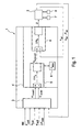
- Fig. 1 schematically represents an embodiment of a device according to the invention again.
- the device comprises a regulator device 1, with which an actuator 2 of an electromechanically actuated brake via a control variable U, for example, a voltage is controlled.
- U for example, a voltage
- the application force F is the brake measured.
- the respective current actuator position is ⁇ is measured by a position measuring system 8.
- the Aktuatorpositionsunk can be realized by measuring an angle, for example, the actuator or a transmission downstream of the actuator, or a position, for example, an axial position of a spindle driven by the actuator.
- the actuator speed n is (or actuator speed) is formed, for example, by differentiating the signal of the position measuring system 8 corresponding to the measured actuator position. Alternatively or additionally, the actuator speed n is also measured with an additional actuator speed sensor.
- Control device 1 comprises a selection and evaluation device 3 and a controller structure 4.
- Selection and evaluation 3 are as inputs a control mode parameter MX, which determines the desired control mode (force control or position control or speed control) of the regulator device 1, and at least one target value F soll , ⁇ soll , ⁇ soll , n should be supplied as a reference variable for the control.
- the selection and evaluation device 3 Independently of the control mode, the selection and evaluation device 3 outputs a desired value ⁇ in-soll and an actual value ⁇ in-is a predetermined actuator variable (eg actuator position ⁇ or actuator clamping force F or actuator speed n), which the controller structure 4 as controller structure input setpoint and controller structure Input actual value (controller structure input variables).
- actuator variable eg actuator position ⁇ or actuator clamping force F or actuator speed n
- the preset actuator variable is the actuator position
- the selection and evaluation device 3 outputs a position desired value and a position actual value as controller structure input setpoint value ⁇ in-soll and controller structure input actual value ⁇ in-ist at controller structure 4.
- the selection and evaluation device 3, as an example, according to the input variables are also the Aktuatorspannkraft actual value F is and the Aktuatorposition actual value ⁇ is supplied.
- Controller structure 4 includes, for example, a position controller 5 (P controller) and a speed controller 6 (PI controller) connected downstream of the position controller 5.
- Position controller 5 outputs, as output variable, an actuator speed setpoint n off-soll , which is transferred as an input variable to the downstream speed controller 6.
- the speed controller 6 is supplied as input of the actuator speed actual value n ist .
- Aktuator horrinum may be present 9, n outputted from the position controller 5 actuator velocity setpoint from setpoint n max limited to a predetermined maximum value, to protect the actuator 2 from being damaged.
- Fig. 1 illustrated device or the implementation of a method according to the invention is hereinafter, in particular in connection with Fig. 2 and 3 , explained in more detail.
- Fig. 2 schematically an embodiment of a method according to the invention for performing a force control is shown.
- the regulator device 1 at least one Aktuatorspannkraft actual value F, and a Aktuatorspannkraft setpoint F should fed as input variables.
- a corresponding actual value ⁇ in is determined from the actuator tensioning force actual value F ist and the actuator tensioning force setpoint F soll and a corresponding desired value ⁇ in-soll is determined for the actuator position. This is done with the help of a given functional Relationship f between the actuator position ⁇ and the Aktuatorspannkraft F, which is characteristic of the brake used.
- the functional relationship f which in Fig.
- Position controller 5 has the task that the actual value ⁇ in-ist the setpoint ⁇ in-soll follows, ie that the position error ⁇ 5 is zero.
- the output of the position controller 5 is a corresponding setpoint n aus-soll for the subsequent speed controller 6.
- the speed controller 6 evaluates the deviation .DELTA.n 6 between the Aktuator Norway setpoint n out-soll and the Aktuator für actual value n is , which also supplied to the speed controller 6 is, and outputs a corresponding manipulated variable U to the actuator 2 (see Fig. 1 ).
- Fig. 3 schematically an embodiment of a method according to the invention for performing a speed control is shown.
- a velocity control (indicated by a parameter control mode M2) to the regulator device 1
- the selection and evaluation device 3 in-soll is determined for the actuator in such a way from the actuator speed nominal value n to a target value of ⁇ that the following of the position regulator 5 output actuator speed setpoint n out-should correspond to the selection and evaluation device 3 supplied Aktuator Malawi setpoint n soll .
- the actuator speed setpoint n soll is divided by the gain K p (block 10) and the actuator position actual value ⁇ is added (block 11) ).
- the result is fed to the position controller 5 as setpoint value ⁇ in-soll together with the actuator position actual value ⁇ is as controller structure input variables ⁇ in-soll , ⁇ in-ist . It then follows a regulation by position controller 5 and speed controller 6 as in connection with Fig. 2 explained.
- a position control can be distinguished between two types of control: a "relative" position control (characterized by a control mode parameter M3), in which the regulator device 1 in addition to the Aktuatorposition actual value ⁇ is a relative Aktuatorposition-target value ⁇ soll is supplied as input, wherein the relative Aktuatorposition setpoint ⁇ soll corresponds to a desired actuator position change, as well as an "absolute" position control (characterized by a control mode parameter M4), in which the regulator device 1 in addition to the Aktuatorposition actual value ⁇ is an absolute Aktuatorposition setpoint ⁇ soll supplied as input is, wherein the Aktuatorposition setpoint ⁇ soll corresponds to the desired absolute actuator position.
- a "relative" position control characterized by a control mode parameter M3
- the regulator device 1 in addition to the Aktuatorposition actual value ⁇ is a relative Aktuatorposition-target value ⁇ soll is supplied as input
- the relative Aktuatorposition setpoint ⁇ soll corresponds to
- the actuator position ⁇ is temporarily stored temporarily in a temporary memory, for example in the selection and evaluation device 3, so that upon entry into the "relative" position control M3 an actuator position value ⁇ store is available from a time shortly before the entry into the position control M3.
- the actuator position desired value and actual value ⁇ soll fed to the selection and evaluation device 3 is simply fed directly to the position controller 5 as controller structure input setpoint value ⁇ in-soll and controller structure input actual value ⁇ in-ist .
- the selection and evaluation device 3 provides the controller structure input quantities ⁇ in-soll , ⁇ in-is such for the controller structure 4 that the controller device 1 with the same controller structure 4 is a force controller for setting an actuator clamping force setpoint or a position control for setting a Aktuatorposition setpoint or a speed control for setting an Aktuator loftiere setpoint can perform.
- Control device 1 represents a dynamic balancing device and ensures that according to the selected control mode force control M1 or speed control M2 or position control M3, M4, the clamping force or the actuator speed or the actuator position of the corresponding reference variable Aktuatorspannkraft setpoint F soll , actuator speed setpoint n soll or (absolute or relative) Aktuatorposition setpoint ⁇ soll , ⁇ soll follows.
- Brake system 20 comprises a central control unit ECU and at least one electrically operable brake 22, which can be actuated by an actuator 2, which is controlled by a control device 1.
- a control device 1 which controls the central control unit ECU.
- the central control unit ECU is connected to the regulator devices 1 (connections 21 are in Fig. 4 shown schematically).
- the central control unit ECU is based on the control unit ECU information and requirements, such as driver brake request, requirements of a slip control system (ABS: antilock braking system, TCS: traction control system) or driver assistance system (ESC: electronic stability control), Initialtechnischsanbig, request for L fullyinstituingna, etc., a decision on the desired control mode (force control M1 or speed control M2 or position control M3, M4) made, which is passed in the form of the control mode parameter MX to the regulator devices 1. Furthermore, the central control unit ECU the control devices 1 according to the requirement and the desired control mode, a setpoint (F soll , ⁇ soll , ⁇ soll , n soll ) as a reference variable for the scheme before.
- a setpoint F soll , ⁇ soll , ⁇ soll , n soll
- a regulator device which can perform the described types of control modes M1-M4, is advantageous in order to be able to fulfill various requirements for the brake.
- a force control is performed, for example, to set the desired braking force by the driver or slip-controlled braking.
- a position control is performed, for example, to adjust the clearance in a disc brake, ie, the distance between the brake disc and the displaceable brake pad to a predetermined value.
- a position control is performed to bring the actuator in the proper position for engaging the lock.
- a speed control can be performed, for example, to determine the stop of the actuator facing away from the brake pads.
Landscapes
- Engineering & Computer Science (AREA)
- Transportation (AREA)
- Mechanical Engineering (AREA)
- Regulating Braking Force (AREA)
- Braking Systems And Boosters (AREA)
- Control Of Electric Motors In General (AREA)
Claims (14)
- Procédé de régulation d'un frein pouvant être actionné électriquement à l'aide d'un actionneur (2), selon lequel sont déterminées une valeur réelle de la force de serrage de l'actionneur (Fist) à l'aide d'un capteur de force de serrage (7) et une valeur réelle de la position de l'actionneur (ϕist) et/ou une valeur réelle de la vitesse de l'actionneur (nist) à l'aide d'un capteur de position (8), et selon lequel une grandeur de réglage (U) destinée à commander l'actionneur (2) est générée à l'aide d'un appareil de régulation (1), caractérisé en ce que l'appareil de régulation (1) comprend un dispositif de sélection et d'interprétation (3) et une structure de régulation (4), le dispositif de sélection et d'interprétation (3) acheminant à la structure de régulation (4) en tant que grandeurs d'entrée de la structure de régulation une valeur de consigne d'entrée de structure de régulation (ϕin-soll) et une valeur réelle d'entrée de structure de régulation (ϕin-ist), et les grandeurs d'entrée de la structure de régulation (ϕin-soll, ϕin-ist) étant mises à disposition par le dispositif de sélection et d'interprétation (3) de telle sorte que l'appareil de régulation (1) peut fonctionner avec la même structure de régulation (4) dans au moins deux des modes de régulation Régulation de la force (M1) en vue de régler une valeur de consigne de la force de serrage de l'actionneur (Fsoll) ou Régulation de la position (M3, M4) en vue de régler une valeur de consigne de la position de l'actionneur (ϕsoll, Δϕsoll) ou Régulation de la vitesse (M2) en vue de régler une valeur de consigne de la vitesse de l'actionneur (nsoll).
- Procédé selon la revendication 1, caractérisé en ce que le dispositif de sélection et d'interprétation (3) achemine à la structure de régulation (4) la même grandeur physique d'actionneur prédéfinie (ϕ) en tant que grandeurs d'entrée de la structure de régulation dans chaque mode de régulation (M1, M2, M3, M4).
- Procédé selon l'une des revendications 1 ou 2, caractérisé en ce que les grandeurs d'entrée acheminées au dispositif de sélection et d'interprétation (3) sont un paramètre de mode de régulation (MX) qui détermine le mode de régulation (M1, M2, M3, M4) à exécuter par l'appareil de régulation (1) et aussi, notamment en fonction du paramètre de mode de régulation (MX), au moins une valeur réelle d'actionneur (Fist, ϕist) et au moins une valeur de consigne d'actionneur (Fsoll, ϕsoll, Δϕsoll, nsoll).
- Procédé selon la revendication 3, caractérisé en ce que la valeur réelle de la force de serrage de l'actionneur (Fist) et la valeur réelle de la position de l'actionneur (ϕist) sont acheminées au dispositif de sélection et d'interprétation (3) et en ce que le dispositif de sélection et d'interprétation (3) interprète la valeur réelle de la force de serrage de l'actionneur (Fist) ou la valeur réelle de la position de l'actionneur (ϕist) en fonction du paramètre de mode de régulation (MX) en vue de déterminer la valeur de consigne d'entrée de structure de régulation (ϕin-soll).
- Procédé selon l'une des revendications 2 à 4, caractérisé en ce que la structure de régulation (4) comprend au moins un régulateur de position (5) et en ce que le dispositif de sélection et d'interprétation (3) achemine à la structure de régulation (4) en tant que grandeurs d'entrée de la structure de régulation dans chaque mode de régulation (M1, M2, M3, M4) une position de l'actionneur (ϕ) pour la valeur de consigne d'entrée de structure de régulation (ϕin-soll) et la valeur réelle d'entrée de structure de régulation (ϕin-ist).
- Procédé selon la revendication 5, caractérisé en ce que la structure de régulation (4) comprend un régulateur de position (5) et un régulateur de vitesse (6) branché en aval du régulateur de position (5), les grandeurs d'entrée acheminées au régulateur de vitesse (6) étant une valeur de consigne de vitesse de l'actionneur (naus-soll) délivrée par le régulateur de position (5) et la valeur réelle de la vitesse de l'actionneur (nist).
- Procédé selon la revendication 5 ou 6, caractérisé en ce que dans le mode de régulation Régulation de la force (M1), au moins une valeur de consigne de la force de serrage de l'actionneur (Fsoll) et une valeur réelle de la force de serrage de l'actionneur (Fist) sont acheminées au dispositif de sélection et d'interprétation (3), en ce que dans le dispositif de sélection et d'interprétation (3), à l'aide d'une relation prédéfinie (f) entre la position de l'actionneur (ϕ) et la force de serrage de l'actionneur (F), sont déterminées une valeur de consigne d'entrée de structure de régulation (ϕin-soll) à partir de la valeur de consigne de la force de serrage de l'actionneur (Fsoll) et une valeur réelle d'entrée de structure de régulation (ϕin-ist) à partir de la valeur réelle de la force de serrage de l'actionneur (Fist), et en ce que la valeur de consigne d'entrée de structure de régulation (ϕin-soll) déterminée et la valeur réelle d'entrée de structure de régulation (ϕin-ist) déterminée sont acheminées au régulateur de position (5) de la structure de régulation (4) en tant que grandeurs d'entrée de la structure de régulation (ϕin-soll, ϕin-ist).
- Procédé selon l'une des revendications 5 à 7, caractérisé en ce que dans le mode de régulation Régulation de la vitesse (M2), au moins une valeur de consigne de la vitesse de l'actionneur (nsoll) et une valeur réelle de la position de l'actionneur (ϕist) sont acheminées au dispositif de sélection et d'interprétation (3), en ce qu'une valeur de consigne d'entrée de structure de régulation (ϕin-soll) est déterminée dans le dispositif de sélection et d'interprétation (3) à partir de la valeur de consigne de la vitesse de l'actionneur (nsoll), et en ce que la valeur de consigne d'entrée de structure de régulation (ϕin-soll) déterminée et la valeur réelle de la position de l'actionneur (ϕist) sont acheminées au régulateur de position (5) de la structure de régulation (4) en tant que grandeurs d'entrée de la structure de régulation (ϕin-soll, ϕin-ist).
- Procédé selon la revendication 8 en référence à la revendication 6 ou 7, caractérisé en ce que la valeur de consigne d'entrée de structure de régulation (ϕin-soll) est calculée à partir de la valeur de consigne de la vitesse de l'actionneur (nsoll), laquelle est acheminée au dispositif de sélection et d'interprétation (3), de telle sorte que la valeur de consigne de vitesse de l'actionneur (naus-soll) délivrée par le régulateur de position (5) est approximativement égale à la valeur de consigne de la vitesse de l'actionneur (nsoll) qui est acheminée au dispositif de sélection et d'interprétation (3).
- Procédé selon l'une des revendications 5 à 9, caractérisé en ce que l'appareil de régulation (1) peut fonctionner dans un mode de régulation (M3) avec régulation de la position relative, dans laquelle au moins une valeur de consigne de la position relative de l'actionneur, laquelle indique la modification de position souhaitée (Δϕsoll) de la position de l'actionneur, et une valeur réelle de la position de l'actionneur (ϕist) sont acheminées au dispositif de sélection et d'interprétation (3), en ce qu'une valeur de consigne d'entrée de structure de régulation (ϕin-soll) est déterminée dans le dispositif de sélection et d'interprétation (3) à partir de la valeur de consigne de la position relative de l'actionneur (Δϕsoll) et d'une valeur de la position de l'actionneur (ϕstore) mise en mémoire avant l'entrée dans le mode de régulation (M3) avec régulation de la position relative, et en ce que la valeur de consigne d'entrée de structure de régulation (ϕin-soll) déterminée et la valeur réelle de la position de l'actionneur (ϕist) sont acheminées au régulateur de position (5) de la structure de régulation (4) en tant que grandeurs d'entrée de la structure de régulation (ϕin-soll, ϕin-ist).
- Appareil de régulation d'un frein pouvant être actionné électriquement à l'aide d'un actionneur (2), comprenant un capteur de force de serrage (7) destiné à déterminer une valeur réelle de la force de serrage de l'actionneur (Fist), un capteur de position (8) destiné à déterminer une valeur réelle de la position de l'actionneur (ϕist) et/ou une valeur réelle de la vitesse de l'actionneur (nist), et comprenant un appareil de régulation (1) qui génère une grandeur de réglage (U) avec laquelle est commandé l'actionneur (2), caractérisé en ce que l'appareil de régulation (1) comprend un dispositif de sélection et d'interprétation (3) et une structure de régulation (4), une valeur de consigne d'entrée de structure de régulation (ϕin-soll) et une valeur réelle d'entrée de structure de régulation (ϕin-ist) étant acheminées à la structure de régulation (4) par le dispositif de sélection et d'interprétation (3) en tant que grandeurs d'entrée de la structure de régulation, et le dispositif de sélection et d'interprétation (3) mettant à disposition de la structure de régulation (4) les grandeurs d'entrée de la structure de régulation (ϕin-soll, (ϕin-ist) de telle sorte que l'appareil de régulation (1) peut fonctionner avec la même structure de régulation (4) dans au moins deux des modes de régulation Régulation de la force (M1) en vue de régler une valeur de consigne de la force de serrage de l'actionneur (Fsoll) ou Régulation de la position (M3, M4) en vue de régler une valeur de consigne de la position de l'actionneur (ϕsoll, Δϕsoll) ou Régulation de la vitesse (M2) en vue de régler une valeur de consigne de la vitesse de l'actionneur (nsoll).
- Appareil selon la revendication 11, caractérisé en ce que le dispositif de sélection et d'interprétation (3) est réalisé de telle sorte que la même grandeur physique d'actionneur prédéfinie (ϕ) pour la grandeur de consigne d'entrée de structure de régulation et la grandeur d'entrée réelle de structure de régulation est acheminée à la structure de régulation (4) en tant que grandeurs d'entrée de la structure de régulation par le dispositif de sélection et d'interprétation (3) dans chaque mode de régulation (M1, M2, M3, M4).
- Appareil selon la revendication 11 ou 12, caractérisé en ce que la structure de régulation (4) comprend au moins un régulateur de position (5) et un régulateur de vitesse (6) branché en aval du régulateur de position (5), une position de l'actionneur (ϕ) pour la valeur de consigne d'entrée de structure de régulation (ϕin-soll) et la valeur réelle d'entrée de structure de régulation (ϕin-ist) étant acheminée au régulateur de position (5) par le dispositif de sélection et d'interprétation (3) en tant que grandeurs d'entrée de la structure de régulation dans chaque mode de régulation (M1, M2, M3, M4), et une valeur de consigne de vitesse de l'actionneur (naus-soll) délivrée par le régulateur de position (5) et la valeur réelle de la vitesse de l'actionneur (nist) étant acheminées au régulateur de vitesse (6) en tant que grandeurs d'entrée.
- Système de frein électronique (20) pour un véhicule automobile, comprenant au moins un frein (22) pouvant être actionné électriquement à l'aide d'un actionneur (2) pour une fonction de frein de service et/ou d'immobilisation, et comprenant une unité de contrôle et de régulation (ECU), caractérisé en ce que l'unité de contrôle et de régulation (ECU) possède au moins un appareil selon l'une des revendications 11 à 13 ou est reliée (21) avec au moins un appareil selon l'une des revendications 11 à 13.
Priority Applications (1)
| Application Number | Priority Date | Filing Date | Title |
|---|---|---|---|
| EP11721018.7A EP2582561B1 (fr) | 2010-06-15 | 2011-05-11 | Procédé et dispositif de réglage d'un frein à actionnement électrique et système de freinage électronique |
Applications Claiming Priority (4)
| Application Number | Priority Date | Filing Date | Title |
|---|---|---|---|
| EP10464005 | 2010-06-15 | ||
| DE102010038306A DE102010038306A1 (de) | 2010-06-15 | 2010-07-23 | Verfahren und Vorrichtung zur Regelung einer elektrisch betätigbaren Bremse sowie elektronisches Bremssystem |
| EP11721018.7A EP2582561B1 (fr) | 2010-06-15 | 2011-05-11 | Procédé et dispositif de réglage d'un frein à actionnement électrique et système de freinage électronique |
| PCT/EP2011/057610 WO2011157492A1 (fr) | 2010-06-15 | 2011-05-11 | Procédé et dispositif de réglage d'un frein à actionnement électrique et système de freinage électronique |
Publications (2)
| Publication Number | Publication Date |
|---|---|
| EP2582561A1 EP2582561A1 (fr) | 2013-04-24 |
| EP2582561B1 true EP2582561B1 (fr) | 2014-11-19 |
Family
ID=45020132
Family Applications (1)
| Application Number | Title | Priority Date | Filing Date |
|---|---|---|---|
| EP11721018.7A Active EP2582561B1 (fr) | 2010-06-15 | 2011-05-11 | Procédé et dispositif de réglage d'un frein à actionnement électrique et système de freinage électronique |
Country Status (6)
| Country | Link |
|---|---|
| US (1) | US8606477B2 (fr) |
| EP (1) | EP2582561B1 (fr) |
| KR (1) | KR101726474B1 (fr) |
| CN (1) | CN102947154B (fr) |
| DE (1) | DE102010038306A1 (fr) |
| WO (1) | WO2011157492A1 (fr) |
Families Citing this family (8)
| Publication number | Priority date | Publication date | Assignee | Title |
|---|---|---|---|---|
| JP5637067B2 (ja) * | 2011-05-24 | 2014-12-10 | 株式会社アドヴィックス | 電動ブレーキ装置および電動ブレーキ装置の制御方法 |
| US10220824B2 (en) | 2014-09-25 | 2019-03-05 | Continental Automotive Systems, Inc. | Electronic brake support system for use when service brake system has failed or is degraded |
| US9311761B1 (en) | 2014-11-21 | 2016-04-12 | Continental Automotive Systems, Inc. | Vehicle load information system to determine road slope and load when trailer is added to vehicle |
| IT201600131985A1 (it) * | 2016-12-29 | 2018-06-29 | Freni Brembo Spa | Metodo di controllo di un’azione frenante esercitabile da una pinza freno su un organo meccanico di movimento di un veicolo e relativo sistema di controllo. |
| DE102019109977B4 (de) * | 2018-05-15 | 2024-03-28 | Schaeffler Technologies AG & Co. KG | Verfahren zur Referenzierung eines Endanschlages eines hydrostatischen Kupplungsaktors |
| DE102020214600A1 (de) * | 2020-11-19 | 2022-05-19 | Robert Bosch Gesellschaft mit beschränkter Haftung | Steuerverfahren zum Verstellen einer elektromechanischen Feststellbremse |
| EP4201766A1 (fr) * | 2021-12-22 | 2023-06-28 | Haldex Brake Products Aktiebolag | Système de frein pour un véhicule commercial |
| CN116373867A (zh) * | 2023-04-11 | 2023-07-04 | 菲格智能科技有限公司 | 制动控制方法、装置、设备、存储介质及车辆 |
Family Cites Families (22)
| Publication number | Priority date | Publication date | Assignee | Title |
|---|---|---|---|---|
| DE19502925A1 (de) | 1995-01-31 | 1996-08-01 | Teves Gmbh Alfred | Verfahren zum Betrieb eines elektronisch regelbaren Bremsbetätigungssystems |
| DE19538794A1 (de) | 1995-10-18 | 1997-04-24 | Teves Gmbh Alfred | Elektronisch regelbares Bremsbetätigungssystem |
| DE19730094A1 (de) | 1997-07-14 | 1999-01-21 | Itt Mfg Enterprises Inc | System zum Steuern oder Regeln einer elektromechanischen Bremse |
| WO1999026822A1 (fr) * | 1997-11-22 | 1999-06-03 | Continental Teves Ag & Co. Ohg | Systeme de freinage electromecanique |
| US6209689B1 (en) | 1997-11-22 | 2001-04-03 | Continental Teves Ag & Co., Ohg | Method and system for actuating an electromechanically operable parking brake for automotive vehicles |
| WO2001068428A1 (fr) * | 2000-03-15 | 2001-09-20 | Continental Teves Ag & Co. Ohg | Procede et systeme de regulation pour creer des forces de tension definies |
| JP4654547B2 (ja) | 2001-07-24 | 2011-03-23 | トヨタ自動車株式会社 | ブレーキ装置 |
| JP2003194119A (ja) * | 2001-12-28 | 2003-07-09 | Nissan Motor Co Ltd | 電動ブレーキ装置 |
| US7018001B2 (en) | 2002-02-22 | 2006-03-28 | Delphi Technologies, Inc. | Fast mode release in a force generating apparatus |
| DE10302515B4 (de) | 2003-01-23 | 2014-09-25 | Robert Bosch Gmbh | Vorrichtung und Verfahren zur Kraft- und/oder Positionsregelung eines elektrischen Bremssystems eines Kraftfahrzeugs |
| DE102005011267A1 (de) | 2004-04-17 | 2006-03-30 | Continental Teves Ag & Co. Ohg | Verfahren und Regelsystem zum Aufbringen definierter Spannkräfte |
| DE102005007446A1 (de) * | 2004-04-17 | 2005-11-17 | Continental Teves Ag & Co. Ohg | Verfahren und Regelsystem zum Aufbringen definierter Spannkräfte |
| DE602005019563D1 (de) * | 2004-06-04 | 2010-04-08 | Goodrich Corp | Messung und steuerung von position und kraft bei elektrischen bremsen |
| JP4155236B2 (ja) * | 2004-07-09 | 2008-09-24 | トヨタ自動車株式会社 | 車両用駆動装置の制御装置 |
| JP4430508B2 (ja) | 2004-10-18 | 2010-03-10 | 本田技研工業株式会社 | ブレーキ装置 |
| DE102005055751C5 (de) | 2005-04-21 | 2025-04-24 | Ipgate Ag | Druckmodulatorsteuerung |
| DE102006040424A1 (de) | 2006-08-29 | 2008-03-06 | Continental Teves Ag & Co. Ohg | Bremssystem für Kraftfahrzeuge |
| JP4297178B2 (ja) | 2007-04-10 | 2009-07-15 | トヨタ自動車株式会社 | ブレーキ制御装置 |
| FR2924082A3 (fr) | 2007-11-28 | 2009-05-29 | Renault Sas | Systeme de freinage decouple pour vehicule automobile |
| DE102009008944B4 (de) | 2009-02-13 | 2024-03-14 | Ipgate Ag | Bremssystem mit simultanem bzw. teilsimultanem Druckauf- und Druckabbau in den Radbremsen aus unterschiedlichen Radzylinderdruckniveaus sowie Verfahren zur Einstellung eines Bremsdrucks |
| DE102010002406B4 (de) | 2010-02-26 | 2012-01-26 | Robert Bosch Gmbh | Hydraulisches Bremssystem und Verfahren sowie Steuergerät zu dessen Betrieb |
| US20110226569A1 (en) * | 2010-03-19 | 2011-09-22 | Hydro-Aire, Inc. | Electronic motor actuators brake inhibit for aircraft braking system |
-
2010
- 2010-07-23 DE DE102010038306A patent/DE102010038306A1/de not_active Withdrawn
-
2011
- 2011-05-11 CN CN201180029400.XA patent/CN102947154B/zh active Active
- 2011-05-11 WO PCT/EP2011/057610 patent/WO2011157492A1/fr not_active Ceased
- 2011-05-11 KR KR1020137001005A patent/KR101726474B1/ko active Active
- 2011-05-11 US US13/703,762 patent/US8606477B2/en not_active Expired - Fee Related
- 2011-05-11 EP EP11721018.7A patent/EP2582561B1/fr active Active
Also Published As
| Publication number | Publication date |
|---|---|
| DE102010038306A1 (de) | 2011-12-15 |
| EP2582561A1 (fr) | 2013-04-24 |
| WO2011157492A1 (fr) | 2011-12-22 |
| CN102947154A (zh) | 2013-02-27 |
| US8606477B2 (en) | 2013-12-10 |
| KR20130098981A (ko) | 2013-09-05 |
| CN102947154B (zh) | 2014-11-26 |
| US20130090827A1 (en) | 2013-04-11 |
| KR101726474B1 (ko) | 2017-04-12 |
Similar Documents
| Publication | Publication Date | Title |
|---|---|---|
| EP2582561B1 (fr) | Procédé et dispositif de réglage d'un frein à actionnement électrique et système de freinage électronique | |
| EP3595958B1 (fr) | Évaluation de la force de crémaillère dans un système de direction à commande électrique de type steer-by-wire | |
| EP3172550B1 (fr) | Procédé et banc d'essai pour tester un raccordement de composants d'un véhicule | |
| EP0642435B1 (fr) | Procede de regulation de la pression de freinage au moyen d'un systeme servo | |
| EP3727998B1 (fr) | Procédé destiné à faire fonctionner un système de direction à orientation par câbles pour un véhicule automobile et système de direction pour un véhicule automobile | |
| WO2021058405A1 (fr) | Procédé et dispositif de guidage latéral simultané de véhicule par un conducteur et par un système d'assistance au moyen d'actionneurs de direction électrique | |
| EP3496970B1 (fr) | Procédé et dispositif pour faire fonctionner un véhicule à moteur et véhicule à moteur | |
| EP2432670B1 (fr) | Système de freinage à frein continu intégré | |
| EP0985586B1 (fr) | Système d'antiblocage pour un système de freinage électromécanique de véhicule basé sur un régulateur de logique floue | |
| DE102021201046A1 (de) | Verfahren zur Steuerung eines Bremssystems | |
| DE10325484A1 (de) | Verfahren zum Lenken eines Fahrzeugs mit einer Überlagerungslenkung | |
| WO2013186026A2 (fr) | Procédé pour augmenter le taux de récupération | |
| DE102011085545A1 (de) | Verfahren und Vorrichtung zum Betreiben eines Kraftfahrzeugs | |
| DE102009000246A1 (de) | Automatisches Kalibrierungsverfahren für einen Indexsensor eines elektronischen Servolenksystems eines Kraftfahrzeugs | |
| DE102010038307B4 (de) | Verfahren und Vorrichtung zur Regelung und/oder Überwachung einer elektrisch betätigbaren Bremse sowie elektronisches Bremssystem | |
| DE19949258A1 (de) | Bremsanlage für Kraftfahrzeuge | |
| WO2011150998A1 (fr) | Procédé de fonctionnement de deux moteurs et véhicule automobile équipée de deux moteurs entraînant des roues désaccouplées | |
| DE102004028828A1 (de) | Verfahren zum Betrieb eines Lenksystems eines Kraftfahrzeugs | |
| DE102022204709A1 (de) | Bremsvorrichtung, elektromechanisches Bremssystem und Verfahren zum Betreiben eines elektromechanischen Bremssystems | |
| DE10355794A1 (de) | Koordination eines Fahrzeugstabilisierungssystems mit einem externen Fahrdynamikregelungssystem | |
| DE102022205961A1 (de) | Verfahren zum Betreiben eines Kraftfahrzeugs, Vorrichtung zum Betreiben eines Kraftfahrzeugs, Kraftfahrzeug | |
| DE102021207447A1 (de) | Verfahren zum Betreiben eines Bremssystems eines Fahrzeugs | |
| WO2016020228A1 (fr) | Circuit de régulation et ensemble de circuit pour la commande d'un système de freinage pour véhicules automobiles | |
| DE102024118050A1 (de) | Lenkeinrichtung, sowie Verfahren zum Betrieb einer Lenkeinrichtung | |
| DE102024204872A1 (de) | Verfahren zur Beeinflussung einer Lenkeinrichtung eines Fahrzeugs |
Legal Events
| Date | Code | Title | Description |
|---|---|---|---|
| PUAI | Public reference made under article 153(3) epc to a published international application that has entered the european phase |
Free format text: ORIGINAL CODE: 0009012 |
|
| 17P | Request for examination filed |
Effective date: 20130115 |
|
| AK | Designated contracting states |
Kind code of ref document: A1 Designated state(s): AL AT BE BG CH CY CZ DE DK EE ES FI FR GB GR HR HU IE IS IT LI LT LU LV MC MK MT NL NO PL PT RO RS SE SI SK SM TR |
|
| DAX | Request for extension of the european patent (deleted) | ||
| GRAP | Despatch of communication of intention to grant a patent |
Free format text: ORIGINAL CODE: EPIDOSNIGR1 |
|
| RIC1 | Information provided on ipc code assigned before grant |
Ipc: B60T 13/74 20060101AFI20140604BHEP Ipc: B60T 8/17 20060101ALI20140604BHEP |
|
| INTG | Intention to grant announced |
Effective date: 20140624 |
|
| GRAS | Grant fee paid |
Free format text: ORIGINAL CODE: EPIDOSNIGR3 |
|
| GRAA | (expected) grant |
Free format text: ORIGINAL CODE: 0009210 |
|
| AK | Designated contracting states |
Kind code of ref document: B1 Designated state(s): AL AT BE BG CH CY CZ DE DK EE ES FI FR GB GR HR HU IE IS IT LI LT LU LV MC MK MT NL NO PL PT RO RS SE SI SK SM TR |
|
| REG | Reference to a national code |
Ref country code: GB Ref legal event code: FG4D Free format text: NOT ENGLISH |
|
| REG | Reference to a national code |
Ref country code: CH Ref legal event code: EP |
|
| REG | Reference to a national code |
Ref country code: AT Ref legal event code: REF Ref document number: 696809 Country of ref document: AT Kind code of ref document: T Effective date: 20141215 |
|
| REG | Reference to a national code |
Ref country code: IE Ref legal event code: FG4D Free format text: LANGUAGE OF EP DOCUMENT: GERMAN |
|
| REG | Reference to a national code |
Ref country code: DE Ref legal event code: R096 Ref document number: 502011005029 Country of ref document: DE Effective date: 20141231 |
|
| REG | Reference to a national code |
Ref country code: NL Ref legal event code: VDEP Effective date: 20141119 |
|
| REG | Reference to a national code |
Ref country code: LT Ref legal event code: MG4D |
|
| PG25 | Lapsed in a contracting state [announced via postgrant information from national office to epo] |
Ref country code: FI Free format text: LAPSE BECAUSE OF FAILURE TO SUBMIT A TRANSLATION OF THE DESCRIPTION OR TO PAY THE FEE WITHIN THE PRESCRIBED TIME-LIMIT Effective date: 20141119 Ref country code: ES Free format text: LAPSE BECAUSE OF FAILURE TO SUBMIT A TRANSLATION OF THE DESCRIPTION OR TO PAY THE FEE WITHIN THE PRESCRIBED TIME-LIMIT Effective date: 20141119 Ref country code: LT Free format text: LAPSE BECAUSE OF FAILURE TO SUBMIT A TRANSLATION OF THE DESCRIPTION OR TO PAY THE FEE WITHIN THE PRESCRIBED TIME-LIMIT Effective date: 20141119 Ref country code: PT Free format text: LAPSE BECAUSE OF FAILURE TO SUBMIT A TRANSLATION OF THE DESCRIPTION OR TO PAY THE FEE WITHIN THE PRESCRIBED TIME-LIMIT Effective date: 20150319 Ref country code: NL Free format text: LAPSE BECAUSE OF FAILURE TO SUBMIT A TRANSLATION OF THE DESCRIPTION OR TO PAY THE FEE WITHIN THE PRESCRIBED TIME-LIMIT Effective date: 20141119 Ref country code: NO Free format text: LAPSE BECAUSE OF FAILURE TO SUBMIT A TRANSLATION OF THE DESCRIPTION OR TO PAY THE FEE WITHIN THE PRESCRIBED TIME-LIMIT Effective date: 20150219 Ref country code: IS Free format text: LAPSE BECAUSE OF FAILURE TO SUBMIT A TRANSLATION OF THE DESCRIPTION OR TO PAY THE FEE WITHIN THE PRESCRIBED TIME-LIMIT Effective date: 20150319 |
|
| PG25 | Lapsed in a contracting state [announced via postgrant information from national office to epo] |
Ref country code: SE Free format text: LAPSE BECAUSE OF FAILURE TO SUBMIT A TRANSLATION OF THE DESCRIPTION OR TO PAY THE FEE WITHIN THE PRESCRIBED TIME-LIMIT Effective date: 20141119 Ref country code: RS Free format text: LAPSE BECAUSE OF FAILURE TO SUBMIT A TRANSLATION OF THE DESCRIPTION OR TO PAY THE FEE WITHIN THE PRESCRIBED TIME-LIMIT Effective date: 20141119 Ref country code: HR Free format text: LAPSE BECAUSE OF FAILURE TO SUBMIT A TRANSLATION OF THE DESCRIPTION OR TO PAY THE FEE WITHIN THE PRESCRIBED TIME-LIMIT Effective date: 20141119 Ref country code: PL Free format text: LAPSE BECAUSE OF FAILURE TO SUBMIT A TRANSLATION OF THE DESCRIPTION OR TO PAY THE FEE WITHIN THE PRESCRIBED TIME-LIMIT Effective date: 20141119 Ref country code: LV Free format text: LAPSE BECAUSE OF FAILURE TO SUBMIT A TRANSLATION OF THE DESCRIPTION OR TO PAY THE FEE WITHIN THE PRESCRIBED TIME-LIMIT Effective date: 20141119 Ref country code: CY Free format text: LAPSE BECAUSE OF FAILURE TO SUBMIT A TRANSLATION OF THE DESCRIPTION OR TO PAY THE FEE WITHIN THE PRESCRIBED TIME-LIMIT Effective date: 20141119 Ref country code: GR Free format text: LAPSE BECAUSE OF FAILURE TO SUBMIT A TRANSLATION OF THE DESCRIPTION OR TO PAY THE FEE WITHIN THE PRESCRIBED TIME-LIMIT Effective date: 20150220 |
|
| PG25 | Lapsed in a contracting state [announced via postgrant information from national office to epo] |
Ref country code: SK Free format text: LAPSE BECAUSE OF FAILURE TO SUBMIT A TRANSLATION OF THE DESCRIPTION OR TO PAY THE FEE WITHIN THE PRESCRIBED TIME-LIMIT Effective date: 20141119 Ref country code: DK Free format text: LAPSE BECAUSE OF FAILURE TO SUBMIT A TRANSLATION OF THE DESCRIPTION OR TO PAY THE FEE WITHIN THE PRESCRIBED TIME-LIMIT Effective date: 20141119 Ref country code: RO Free format text: LAPSE BECAUSE OF FAILURE TO SUBMIT A TRANSLATION OF THE DESCRIPTION OR TO PAY THE FEE WITHIN THE PRESCRIBED TIME-LIMIT Effective date: 20141119 Ref country code: EE Free format text: LAPSE BECAUSE OF FAILURE TO SUBMIT A TRANSLATION OF THE DESCRIPTION OR TO PAY THE FEE WITHIN THE PRESCRIBED TIME-LIMIT Effective date: 20141119 Ref country code: CZ Free format text: LAPSE BECAUSE OF FAILURE TO SUBMIT A TRANSLATION OF THE DESCRIPTION OR TO PAY THE FEE WITHIN THE PRESCRIBED TIME-LIMIT Effective date: 20141119 |
|
| REG | Reference to a national code |
Ref country code: DE Ref legal event code: R097 Ref document number: 502011005029 Country of ref document: DE |
|
| PLBE | No opposition filed within time limit |
Free format text: ORIGINAL CODE: 0009261 |
|
| STAA | Information on the status of an ep patent application or granted ep patent |
Free format text: STATUS: NO OPPOSITION FILED WITHIN TIME LIMIT |
|
| 26N | No opposition filed |
Effective date: 20150820 |
|
| PG25 | Lapsed in a contracting state [announced via postgrant information from national office to epo] |
Ref country code: IT Free format text: LAPSE BECAUSE OF FAILURE TO SUBMIT A TRANSLATION OF THE DESCRIPTION OR TO PAY THE FEE WITHIN THE PRESCRIBED TIME-LIMIT Effective date: 20141119 |
|
| REG | Reference to a national code |
Ref country code: CH Ref legal event code: PL |
|
| GBPC | Gb: european patent ceased through non-payment of renewal fee |
Effective date: 20150511 |
|
| PG25 | Lapsed in a contracting state [announced via postgrant information from national office to epo] |
Ref country code: CH Free format text: LAPSE BECAUSE OF NON-PAYMENT OF DUE FEES Effective date: 20150531 Ref country code: LU Free format text: LAPSE BECAUSE OF FAILURE TO SUBMIT A TRANSLATION OF THE DESCRIPTION OR TO PAY THE FEE WITHIN THE PRESCRIBED TIME-LIMIT Effective date: 20150511 Ref country code: MC Free format text: LAPSE BECAUSE OF FAILURE TO SUBMIT A TRANSLATION OF THE DESCRIPTION OR TO PAY THE FEE WITHIN THE PRESCRIBED TIME-LIMIT Effective date: 20141119 Ref country code: LI Free format text: LAPSE BECAUSE OF NON-PAYMENT OF DUE FEES Effective date: 20150531 |
|
| REG | Reference to a national code |
Ref country code: IE Ref legal event code: MM4A |
|
| PG25 | Lapsed in a contracting state [announced via postgrant information from national office to epo] |
Ref country code: SI Free format text: LAPSE BECAUSE OF FAILURE TO SUBMIT A TRANSLATION OF THE DESCRIPTION OR TO PAY THE FEE WITHIN THE PRESCRIBED TIME-LIMIT Effective date: 20141119 |
|
| PG25 | Lapsed in a contracting state [announced via postgrant information from national office to epo] |
Ref country code: IE Free format text: LAPSE BECAUSE OF NON-PAYMENT OF DUE FEES Effective date: 20150511 Ref country code: GB Free format text: LAPSE BECAUSE OF NON-PAYMENT OF DUE FEES Effective date: 20150511 |
|
| REG | Reference to a national code |
Ref country code: FR Ref legal event code: PLFP Year of fee payment: 6 |
|
| PG25 | Lapsed in a contracting state [announced via postgrant information from national office to epo] |
Ref country code: MT Free format text: LAPSE BECAUSE OF FAILURE TO SUBMIT A TRANSLATION OF THE DESCRIPTION OR TO PAY THE FEE WITHIN THE PRESCRIBED TIME-LIMIT Effective date: 20141119 |
|
| REG | Reference to a national code |
Ref country code: FR Ref legal event code: PLFP Year of fee payment: 7 |
|
| PG25 | Lapsed in a contracting state [announced via postgrant information from national office to epo] |
Ref country code: HU Free format text: LAPSE BECAUSE OF FAILURE TO SUBMIT A TRANSLATION OF THE DESCRIPTION OR TO PAY THE FEE WITHIN THE PRESCRIBED TIME-LIMIT; INVALID AB INITIO Effective date: 20110511 Ref country code: BG Free format text: LAPSE BECAUSE OF FAILURE TO SUBMIT A TRANSLATION OF THE DESCRIPTION OR TO PAY THE FEE WITHIN THE PRESCRIBED TIME-LIMIT Effective date: 20141119 Ref country code: SM Free format text: LAPSE BECAUSE OF FAILURE TO SUBMIT A TRANSLATION OF THE DESCRIPTION OR TO PAY THE FEE WITHIN THE PRESCRIBED TIME-LIMIT Effective date: 20141119 |
|
| REG | Reference to a national code |
Ref country code: AT Ref legal event code: MM01 Ref document number: 696809 Country of ref document: AT Kind code of ref document: T Effective date: 20160511 |
|
| PG25 | Lapsed in a contracting state [announced via postgrant information from national office to epo] |
Ref country code: BE Free format text: LAPSE BECAUSE OF NON-PAYMENT OF DUE FEES Effective date: 20150531 |
|
| PG25 | Lapsed in a contracting state [announced via postgrant information from national office to epo] |
Ref country code: AT Free format text: LAPSE BECAUSE OF NON-PAYMENT OF DUE FEES Effective date: 20160511 Ref country code: TR Free format text: LAPSE BECAUSE OF FAILURE TO SUBMIT A TRANSLATION OF THE DESCRIPTION OR TO PAY THE FEE WITHIN THE PRESCRIBED TIME-LIMIT Effective date: 20141119 |
|
| REG | Reference to a national code |
Ref country code: FR Ref legal event code: PLFP Year of fee payment: 8 |
|
| PG25 | Lapsed in a contracting state [announced via postgrant information from national office to epo] |
Ref country code: MK Free format text: LAPSE BECAUSE OF FAILURE TO SUBMIT A TRANSLATION OF THE DESCRIPTION OR TO PAY THE FEE WITHIN THE PRESCRIBED TIME-LIMIT Effective date: 20141119 |
|
| PG25 | Lapsed in a contracting state [announced via postgrant information from national office to epo] |
Ref country code: AL Free format text: LAPSE BECAUSE OF FAILURE TO SUBMIT A TRANSLATION OF THE DESCRIPTION OR TO PAY THE FEE WITHIN THE PRESCRIBED TIME-LIMIT Effective date: 20141119 |
|
| REG | Reference to a national code |
Ref country code: DE Ref legal event code: R081 Ref document number: 502011005029 Country of ref document: DE Owner name: CONTINENTAL AUTOMOTIVE TECHNOLOGIES GMBH, DE Free format text: FORMER OWNER: CONTINENTAL TEVES AG & CO. OHG, 60488 FRANKFURT, DE Ref country code: DE Ref legal event code: R081 Ref document number: 502011005029 Country of ref document: DE Owner name: AUMOVIO GERMANY GMBH, DE Free format text: FORMER OWNER: CONTINENTAL TEVES AG & CO. OHG, 60488 FRANKFURT, DE |
|
| REG | Reference to a national code |
Ref country code: DE Ref legal event code: R081 Ref document number: 502011005029 Country of ref document: DE Owner name: CONTINENTAL AUTOMOTIVE TECHNOLOGIES GMBH, DE Free format text: FORMER OWNER: CONTINENTAL AUTOMOTIVE TECHNOLOGIES GMBH, 30165 HANNOVER, DE Ref country code: DE Ref legal event code: R081 Ref document number: 502011005029 Country of ref document: DE Owner name: AUMOVIO GERMANY GMBH, DE Free format text: FORMER OWNER: CONTINENTAL AUTOMOTIVE TECHNOLOGIES GMBH, 30165 HANNOVER, DE |
|
| PGFP | Annual fee paid to national office [announced via postgrant information from national office to epo] |
Ref country code: DE Payment date: 20250531 Year of fee payment: 15 |
|
| PGFP | Annual fee paid to national office [announced via postgrant information from national office to epo] |
Ref country code: FR Payment date: 20250528 Year of fee payment: 15 |
|
| REG | Reference to a national code |
Ref country code: DE Ref legal event code: R081 Ref document number: 502011005029 Country of ref document: DE Owner name: AUMOVIO GERMANY GMBH, DE Free format text: FORMER OWNER: CONTINENTAL AUTOMOTIVE TECHNOLOGIES GMBH, 30175 HANNOVER, DE |