EP2582906B1 - Agencement de meulage pour joints d'outil sur un train de tiges - Google Patents
Agencement de meulage pour joints d'outil sur un train de tiges Download PDFInfo
- Publication number
- EP2582906B1 EP2582906B1 EP11796011.2A EP11796011A EP2582906B1 EP 2582906 B1 EP2582906 B1 EP 2582906B1 EP 11796011 A EP11796011 A EP 11796011A EP 2582906 B1 EP2582906 B1 EP 2582906B1
- Authority
- EP
- European Patent Office
- Prior art keywords
- grinding
- drill string
- unit
- receiving unit
- grinding unit
- Prior art date
- Legal status (The legal status is an assumption and is not a legal conclusion. Google has not performed a legal analysis and makes no representation as to the accuracy of the status listed.)
- Active
Links
- 238000005553 drilling Methods 0.000 claims description 30
- 238000007789 sealing Methods 0.000 claims description 24
- 239000012530 fluid Substances 0.000 claims description 19
- 230000008878 coupling Effects 0.000 claims description 18
- 238000010168 coupling process Methods 0.000 claims description 18
- 238000005859 coupling reaction Methods 0.000 claims description 18
- 239000002245 particle Substances 0.000 claims description 4
- 229920001971 elastomer Polymers 0.000 claims description 3
- 238000002347 injection Methods 0.000 claims description 3
- 239000007924 injection Substances 0.000 claims description 3
- 229920002635 polyurethane Polymers 0.000 claims description 3
- 239000004814 polyurethane Substances 0.000 claims description 3
- 229930195733 hydrocarbon Natural products 0.000 description 8
- 150000002430 hydrocarbons Chemical class 0.000 description 8
- XLYOFNOQVPJJNP-UHFFFAOYSA-N water Substances O XLYOFNOQVPJJNP-UHFFFAOYSA-N 0.000 description 8
- 230000015572 biosynthetic process Effects 0.000 description 6
- 238000004140 cleaning Methods 0.000 description 6
- 238000000034 method Methods 0.000 description 6
- 239000000243 solution Substances 0.000 description 4
- 239000004215 Carbon black (E152) Substances 0.000 description 3
- 238000005520 cutting process Methods 0.000 description 2
- 230000000694 effects Effects 0.000 description 2
- 239000013536 elastomeric material Substances 0.000 description 2
- 238000009434 installation Methods 0.000 description 2
- 239000003129 oil well Substances 0.000 description 2
- 238000012856 packing Methods 0.000 description 2
- 230000009471 action Effects 0.000 description 1
- 230000004888 barrier function Effects 0.000 description 1
- 230000008901 benefit Effects 0.000 description 1
- 230000000295 complement effect Effects 0.000 description 1
- 239000002131 composite material Substances 0.000 description 1
- 238000010276 construction Methods 0.000 description 1
- 238000001816 cooling Methods 0.000 description 1
- 230000001419 dependent effect Effects 0.000 description 1
- 239000013013 elastic material Substances 0.000 description 1
- 238000007667 floating Methods 0.000 description 1
- 239000007788 liquid Substances 0.000 description 1
- 230000001050 lubricating effect Effects 0.000 description 1
- 238000005461 lubrication Methods 0.000 description 1
- 238000004519 manufacturing process Methods 0.000 description 1
- 239000000463 material Substances 0.000 description 1
- 239000012857 radioactive material Substances 0.000 description 1
- 239000012815 thermoplastic material Substances 0.000 description 1
Images

Classifications
-
- B—PERFORMING OPERATIONS; TRANSPORTING
- B08—CLEANING
- B08B—CLEANING IN GENERAL; PREVENTION OF FOULING IN GENERAL
- B08B1/00—Cleaning by methods involving the use of tools
- B08B1/20—Cleaning of moving articles, e.g. of moving webs or of objects on a conveyor
-
- B—PERFORMING OPERATIONS; TRANSPORTING
- B24—GRINDING; POLISHING
- B24B—MACHINES, DEVICES, OR PROCESSES FOR GRINDING OR POLISHING; DRESSING OR CONDITIONING OF ABRADING SURFACES; FEEDING OF GRINDING, POLISHING, OR LAPPING AGENTS
- B24B27/00—Other grinding machines or devices
- B24B27/0053—Radial grinding machines
-
- B—PERFORMING OPERATIONS; TRANSPORTING
- B08—CLEANING
- B08B—CLEANING IN GENERAL; PREVENTION OF FOULING IN GENERAL
- B08B9/00—Cleaning hollow articles by methods or apparatus specially adapted thereto
- B08B9/02—Cleaning pipes or tubes or systems of pipes or tubes
- B08B9/023—Cleaning the external surfaces
-
- B—PERFORMING OPERATIONS; TRANSPORTING
- B24—GRINDING; POLISHING
- B24B—MACHINES, DEVICES, OR PROCESSES FOR GRINDING OR POLISHING; DRESSING OR CONDITIONING OF ABRADING SURFACES; FEEDING OF GRINDING, POLISHING, OR LAPPING AGENTS
- B24B9/00—Machines or devices designed for grinding edges or bevels on work or for removing burrs; Accessories therefor
-
- E—FIXED CONSTRUCTIONS
- E21—EARTH OR ROCK DRILLING; MINING
- E21B—EARTH OR ROCK DRILLING; OBTAINING OIL, GAS, WATER, SOLUBLE OR MELTABLE MATERIALS OR A SLURRY OF MINERALS FROM WELLS
- E21B17/00—Drilling rods or pipes; Flexible drill strings; Kellies; Drill collars; Sucker rods; Cables; Casings; Tubings
- E21B17/006—Accessories for drilling pipes, e.g. cleaners
Definitions
- the present invention relates to a system for removing sharp edges on a pipe coupling of a drill string resulting as a consequence of marks from the jaws of pliers and machines used to connect the pipe couplings on a drill deck.
- the system according to the invention relates to a grinding tool to grind a drill string in wells carrying air, water, drilling fluid or hydrocarbons, comprising at least one grinding unit that is arranged to partially or completely surround the drill string.
- the invention can be used to grind away sharp edges and marks on a drill string that moves into or out of oil wells and gas wells in all water carrying, drilling fluid carrying or hydrocarbon carrying types of wells, both wells that have a valve tree (the well safety valves) placed on the ocean bottom, a platform, a vessel, on an appliance or on land.
- a drill string is any kind of connection of drill pipes with screw connections that are used between a drilling rig or drilling vessel and a well.
- the invention relates to grinding systems for sealing arrangements and methods that make intervention and drilling possible in the above mentioned water carrying, drilling fluid carrying or hydrocarbon carrying wells by using a landing string, riser connection or other connections between the well and the drilling deck on a surface vessel, platform or other installations.
- the invention can also be used over, between or below well control equipment elements, whether the valve tree of the well is placed on the ocean bed or at the surface.
- the sealing arrangement and the method cover normal operation in the above mentioned water carrying, drilling fluid carrying or hydrocarbon carrying wells performed with the help of a drill string and snubbing string, and also said methods based on the use of new composites and thermoplastic materials as well as complementary solutions.
- drill string and snubbing string are hereafter described by the designation drill string.
- downhole tools it must be understood different tools for operations in a well, i.e. equipment for drilling operations, intervention equipment, equipment for logging, measuring, fishing, etc.
- Wells carrying water, drilling fluid or hydrocarbons are hereafter denoted by the expression well.
- the invention will represent a grinding function for a drill string that goes through a seal, while the drill string moves into or out of a well.
- the invention will be particularly suited to operations that include pressure controlled drilling, as the invention appears as a risk reducing unit for any seal that seals against the moving drill string.
- the methods used today to carry out well intervention or drilling in wells with the help of a drill string or coiled tubing are based on using a riser connection between the wellhead and the equipment on the drilling deck. Normally, one drills with a drilling fluid that has a higher specific density than what is expected of pressure from the formation, and normally the top of the riser will then be open with free access to the drilling fluid between the drill string and riser (annular space).
- More and more reservoirs have challenges as a consequence of pressure loss or high pressure and high temperature.
- pressure loss wells the possibility to be able to drill them will increase if the weight of the drilling fluid and thus the pressure on the formation can be reduced.
- a seal must be arranged between the drill string and the riser to be able to tackle a possible pressure from the formation as a consequence of the safety margin being reduced due to the lighter drilling fluid.
- For reservoirs with a high pressure and high temperature it is desirable to be able to maintain the pressure in the formation during drilling. One can achieve this by sealing between the drill string and riser and thereafter pressurising the riser until the pressure at the end of the drill string is equal to the surrounding pressure from the formation. Then, one can drill with a reduced risk of damage to the formation.
- the seals are, as a rule, made from an elastomeric material that both seals on the thin part and the thicker part (the pipe coupling) of the drill string.
- the elastomeric seal will experience a strong tension and a sharp edge which will then goes through the seal will be able to generate open tears and ruptures in the seal.
- the present invention has as an object to reduce the risk when drilling with what is called controlled pressure drilling, which includes one or more seals that seal around a dynamic drill string.
- the seal(s) represents one of the well barriers during operation and is thus a critical element. By removing sharp edges from the drill string the risk of damaging said seals is reduced, as well as the life time of the seal being extended.
- the grinding system has several configurations and these will be adapted to the outer diameter of the string that shall pass through the grinder.
- US 2,682,068 A - Harrigan which relates to a grinding unit which is arranged to clean or grind the outer surface of a drill string.
- the grinding unit is used on pipe strings as they are pulled out of a borehole and then preferably for land-based boreholes.
- US 2,307,449 A - Carpmail shows another example of a device to clean or grind a pipe string.
- NO 327281 B1 - Siem WIS relates to a sealing arrangement for dynamic sealing around a drill string in an oil well and/or a gas well.
- US 2,064,577 A discloses a pipe cleaning apparatus in the form of a pipe cleaning machine.
- the present grinding system to grind a drill string in wells carrying water, drilling fluid or hydrocarbons comprises a grinding arrangement that can be mounted together with other equipment and adjoining systems that are necessary to be able to carry out the operation in the well, whether it is an ocean bed-based well or a surface well, where the grinding arrangement can be a unit that can be brought along for well intervention with the help of a drill string. Furthermore, lubrication or a fluid under pressure can be injected into the grinder to cool between the grinder and drill string and also to remove possible residues after the grinding.
- the drill string can move into, or out of, the well independently of the well pressure.
- the grinding arrangement is preferably controlled, monitored and connected to a suitable control system.
- the system comprises a receiving unit arranged in a riser, landing string or in other connections between the drill deck and a wellhead, and above a sealing arrangement that is used during pressure controlled drilling for dynamic sealing around the drill string, wherein the receiving unit is arranged to receive a grinding unit, said grinding unit is equipped with at least one grinding element, and the grinding unit is locked into the receiving unit after the grinding unit is driven into the receiving unit with the help of the drill string or a suitable running tool.
- the receiving unit can comprise at least one inlet channel for injection of a fluid to cool, lubricate and wash away grinding residues. Furthermore, the inlet channel can run through the grinding unit and end up at an area where the grinding unit abuts the drill string.
- the grinding unit can be permanently fixed in the receiving unit, whereby grinding of the pipe coupling is arranged to be carried out by rotating the drill string.
- grinding of the pipe coupling can be carried out by an axial movement of the drill string.
- the grinding unit can be mounted to rotate in the receiving unit, whereby the grinding of the pipe coupling is arranged to be carried out without rotation of the drill string.
- the grinding elements of the grinding unit can be arranged to be driven into a grinding position that corresponds to the desired ground diameter of the pipe coupling.
- the grinding unit can also be arranged to be driven out of said grinding position.
- the grinding unit can be arranged to take up angle deflections of the drill string, and can also function as a centraliser and movement dampener for the drill string.
- the grinding unit can be locked securely into the receiving unit with the help of a number of locking devices. Furthermore, the grinding unit can be placed in sections in the receiving unit and arranged to be mounted around the drill string.
- the receiving unit can be in an area below the grinding unit adapted to receive a number of seal sets placed after each other, where each seal is arranged to be locked in position with the help of respective locking devices, and arranged mutually spaced apart along the receiving unit.
- the grinding unit can comprise one or more blocks with built-in grinding particles. Said block can be manufactured from rubber or polyurethane.
- the fluid injected into the grinder prevents the possibility of blockage of material that would reduce the effect of the grinder.
- the present invention can be combined with a dynamic sealing arrangement as described in PCT/NO08/00125 (corresponding to NO326492 ).
- a sealing arrangement for dynamic sealing around a drill string or coiled tubing comprising an extended sealing unit which is arranged to surround the drill string, where the sealing unit comprises a number of sets of main seals arranged mutually spaced apart in the longitudinal direction in the sealing unit.
- Said main seals comprise, at least, one disc-formed or ring-formed packing element of an elastic material, such as an elastomeric material, arranged to surround said drill string.
- the main seal comprises at least one inlet channel arranged to receive a friction reducing medium through said seal, directly into the sealing surface of the packing element against the drill string.
- the present invention can be combined with a sealing arrangement as described in PCT/NO08/00274 (corresponding to NO327281 ).
- PCT/NO08/00274 relates to a sealing arrangement for dynamic sealing around a drill string in wells carrying water, drilling fluid or hydrocarbons, comprising at least one dynamic seal 35a which is arranged to surround the drill string 50 and a receiving unit 30 arranged to receive the, at least, one seal 35a, with the dynamic seal being arranged to be driven into the receiving unit 30 with the help of the drill string, and to be locked into the receiving unit.
- Internal pressure support can be provided in the sealing arrangement at least corresponding to the surrounding pressure.
- Said receiving unit 30 can be placed in an area on, or adjacent to, the drill deck of a drilling rig or vessel and in a riser, landing string or other connections between the drill deck and a well.
- the receiving unit is arranged to close the return side of the drilling fluid between the drill string and the upper part of the riser in that the receiving unit 30 is adjusted to receive a number of sealing sets placed after each other, where each seal is arranged to be locked in place with the help of respective locking devices 34a, 34b, 34c arranged mutually spaced apart along the length of the receiving unit.
- the receiving unit 30 can be, in connection with a floating rig or drilling ship, placed below the compensating unit for the riser, or that the receiving unit 30 in connection with a permanent installation is arranged to be a part of the riser connection.
- Figure 1 show an application of the present grinding unit 36 placed in a housing or receiving unit 30.
- the grinding unit 36 and/or the receiving unit 30 can be placed and be pulled with the drill string or with a dedicated running tool or string.
- the grinding unit 36 is preferably locked in place in the receiving unit 30 by the locks 34c and 34d.
- the coupling on drill string 51 normally has a larger diameter than the string 50 itself and when the drill string is moved through the grinding unit 36 the outer surface of the pipe coupling 51 is machined so that the irregularities that form the sharp edges on the pipe coupling are removed. These irregularities often arise as a consequence of marks from the jaws of pliers and machines used to connect the couplings 51 on the drill deck, but can also arise due to other kinds of treatment.
- An injection line 33 can also be arranged to make it possible to inject a fluid for cooling, lubricating and cleaning of the grinding surface.
- the grinding unit 36 is here shown as a free standing unit, although mounted above seals (not shown).
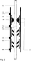
- Figure 2 shows an application of the present grinding unit 36 placed above the seals for the drill string 34a and 34b, and can thus constitute an integrated part.
- the grinding unit 36 and the seals 35a and 35b can be mounted in a common housing or receiving unit 30.
- a typical embodiment of the grinding element or grinding block 38 in the grinding unit can be grinding particles in-built into an adapted block made from polyurethane or rubber. These can thereafter be placed to overlap in the circumference of the drill string or without any overlap.
- the block 38 is formed with a partial pointed contact surface against the drill string 50.
- the block can also be formed with a flat contact surface. This is applicable to the other grinding solutions.
- several blocks or grinding elements can be used, arranged next to each other in the receiving unit 30.
- the grinding unit 36 can be permanently mounted or rotary mounted in the receiving unit 30 and it can also be divided into parts so that it can be mounted around the drill string without the drill string having to be broken.
- grinding particles and solutions that are approved for cold processing, i.e. that they do not create sparks themselves when operating in air.
- any applicable grinding element may be used.
- Other possible solutions are grinding discs, grinding files, grinding heads, etc., which can, in a corresponding way, be built into a block, or which can, in any other way, be set in the grinding unit 36 to provide the described grinding function.
- the grinding arrangement can be localised on a drill deck, in a riser or straight onto a BOP and also subsea without a riser.
- the grinding arrangement can be used on all wells carrying water, gas or hydrocarbons, and also drilling fluid, and can be used both in dry conditions or submersed in a liquid. Furthermore, it can function as a centraliser and movement dampener for the drill string.
Landscapes
- Engineering & Computer Science (AREA)
- Mechanical Engineering (AREA)
- Life Sciences & Earth Sciences (AREA)
- Geology (AREA)
- Mining & Mineral Resources (AREA)
- Physics & Mathematics (AREA)
- Environmental & Geological Engineering (AREA)
- Fluid Mechanics (AREA)
- General Life Sciences & Earth Sciences (AREA)
- Geochemistry & Mineralogy (AREA)
- Earth Drilling (AREA)
- Yarns And Mechanical Finishing Of Yarns Or Ropes (AREA)
Claims (14)
- Système destiné à éliminer les arêtes vives sur un raccord de tuyau (51) d'un train de tiges (50), comprenant :une unité de réception (30) agencée dans une colonne montante, une chaîne de scellement ou dans d'autres raccords entre le pont de forage et une tête de puits, et au-dessus d'un agencement d'étanchéité, qui est utilisé pendant un forage contrôlé en pression pour un scellement dynamique autour du train de tiges (50), dans lequell'unité de réception (30) est agencée afin de recevoir une unité de meulage (36), dans lequel l'unité de meulage (36) est équipée d'au moins un élément de meulage (38), etl'unité de meulage (36) est verrouillée dans l'unité de réception (30) après que l'unité de meulage (36) a été entraînée dans une unité de réception (30) à l'aide du train de tiges (50) ou d'un outil de pilotage adapté.
- Système selon la revendication 1, caractérisé en ce que l'unité de réception (30) comprend au moins un canal d'entrée (33) pour l'injection d'un fluide visant à refroidir, lubrifier et enlever les résidus de meulage.
- Système selon la revendication 2, caractérisé en ce que le canal d'entrée (33) s'étend à travers l'unité de meulage (36) et se termine dans une zone où l'unité de meulage (36) vient en butée sur le train de tiges (50).
- Système selon la revendication 1, caractérisé en ce que l'unité de meulage (36) est montée de manière sécurisée dans l'unité de réception (30), moyennant quoi le meulage du raccord de tuyau (51) est conçu afin d'être réalisé par une rotation du train de tiges (50).
- Système selon la revendication 1, caractérisé en ce que l'unité de meulage (36) est montée de manière sécurisée dans l'unité de réception (30), moyennant quoi le meulage du raccord de tuyau (51) est conçu afin d'être réalisé par un mouvement axial du train de tiges (50).
- Système selon la revendication 1, caractérisé en ce que l'unité de meulage (36) est montée en rotation dans l'unité de réception (30), moyennant quoi le meulage du raccord de tuyau (51) est conçu afin d'être réalisé sans rotation du train de tiges (50).
- Système selon la revendication 1, caractérisé en ce que les éléments de meulage (38) de l'unité de meulage (36) sont conçus afin d'être entraînés dans une position de meulage, qui correspond au diamètre post-meulage souhaité du raccord de tuyau (51).
- Système selon la revendication 7, caractérisé en ce que l'unité de meulage (36) est conçue afin d'être entraînée hors de ladite position de meulage.
- Système selon la revendication 1, caractérisé en ce que l'unité de meulage (36) est conçue afin d'adopter des déflexions angulaires du train de tiges (50).
- Système selon la revendication 1, caractérisé en ce que l'unité de meulage (36) est verrouillée de manière sécurisée dans l'unité de réception (30) à l'aide d'un certain nombre de dispositifs de verrouillage (34c, 34d).
- Système selon la revendication 1, caractérisé en ce que l'unité de meulage (36) est agencée en sections dans l'unité de réception (30) et est agencée afin d'être montée autour du train de tiges (50).
- Système selon la revendication 1, caractérisé en ce que l'unité de réception (30), dans une zone sous l'unité de meulage (36), est conçue afin de recevoir un certain nombre d'ensembles d'étanchéité (35a, 35b) placés les uns à côté des autres, où chaque joint est agencé afin d'être verrouillé de manière sécurisée, à l'aide de dispositifs de verrouillage respectifs (34a, 34b, 34c) agencés de façon à être réciproquement espacés dans la direction longitudinale de l'unité de réception (30).
- Système selon la revendication 1, caractérisé en ce que l'élément de meulage (38) comprend un ou plusieurs bloc(s) de meulage avec des particules de meulage intégrées.
- Système selon la revendication 13, caractérisé en ce que ledit bloc est fabriqué à partir de caoutchouc ou de polyuréthane.
Applications Claiming Priority (2)
| Application Number | Priority Date | Filing Date | Title |
|---|---|---|---|
| NO20100858A NO333082B1 (no) | 2010-06-16 | 2010-06-16 | Slipearrangement for borestreng |
| PCT/NO2011/000166 WO2011159165A1 (fr) | 2010-06-16 | 2011-06-08 | Agencement de meulage pour joints d'outil sur un train de tiges |
Publications (3)
| Publication Number | Publication Date |
|---|---|
| EP2582906A1 EP2582906A1 (fr) | 2013-04-24 |
| EP2582906A4 EP2582906A4 (fr) | 2017-07-26 |
| EP2582906B1 true EP2582906B1 (fr) | 2019-09-18 |
Family
ID=45348384
Family Applications (1)
| Application Number | Title | Priority Date | Filing Date |
|---|---|---|---|
| EP11796011.2A Active EP2582906B1 (fr) | 2010-06-16 | 2011-06-08 | Agencement de meulage pour joints d'outil sur un train de tiges |
Country Status (12)
| Country | Link |
|---|---|
| US (1) | US8997851B2 (fr) |
| EP (1) | EP2582906B1 (fr) |
| AU (1) | AU2011265829B2 (fr) |
| BR (1) | BR112012032165B1 (fr) |
| CA (1) | CA2800940C (fr) |
| DK (1) | DK2582906T3 (fr) |
| EA (1) | EA023675B1 (fr) |
| MX (1) | MX2012014740A (fr) |
| MY (1) | MY178548A (fr) |
| NO (1) | NO333082B1 (fr) |
| SG (1) | SG185793A1 (fr) |
| WO (1) | WO2011159165A1 (fr) |
Families Citing this family (2)
| Publication number | Priority date | Publication date | Assignee | Title |
|---|---|---|---|---|
| US20140027129A1 (en) * | 2011-12-29 | 2014-01-30 | Weatherford/Lamb, Inc. | Annular sealing in a rotating control device |
| US9611723B2 (en) * | 2014-12-17 | 2017-04-04 | Schlumberger Technology Corporation | Heat transferring electronics chassis |
Family Cites Families (36)
| Publication number | Priority date | Publication date | Assignee | Title |
|---|---|---|---|---|
| US1875632A (en) | 1929-02-23 | 1932-09-06 | Joseph H Mcevoy | Universal casing head and gas saver |
| US2064577A (en) * | 1935-06-10 | 1936-12-15 | Thayer Starr | Pipe cleaning apparatus |
| US2222082A (en) | 1938-12-01 | 1940-11-19 | Nat Supply Co | Rotary drilling head |
| US2682068A (en) * | 1950-11-03 | 1954-06-29 | John J Harrigan | Device for externally cleaning oil well casings and pipes |
| US3474858A (en) | 1956-12-10 | 1969-10-28 | Shaffer Tool Works | Method and apparatus for off shore drilling |
| US3215203A (en) | 1961-04-17 | 1965-11-02 | Otis Eng Co | Apparatus for moving a well flow conductor into or out of a well |
| US3387851A (en) | 1966-01-12 | 1968-06-11 | Shaffer Tool Works | Tandem stripper sealing apparatus |
| US3965987A (en) | 1973-03-08 | 1976-06-29 | Dresser Industries, Inc. | Method of sealing the annulus between a toolstring and casing head |
| DE2643769A1 (de) | 1976-09-29 | 1978-03-30 | Howaldtswerke Deutsche Werft | Abdichtung fuer sich drehende wellen |
| US4149603A (en) | 1977-09-06 | 1979-04-17 | Arnold James F | Riserless mud return system |
| US4162704A (en) | 1978-02-23 | 1979-07-31 | Gunther Albert W | Pressure control device |
| US4315553A (en) | 1980-08-25 | 1982-02-16 | Stallings Jimmie L | Continuous circulation apparatus for air drilling well bore operations |
| DE3339316A1 (de) | 1983-10-29 | 1985-05-09 | Rudi 5657 Haan Habermann | Fuehrungsanordnung |
| US5474097A (en) * | 1993-11-10 | 1995-12-12 | Atlantic Richfield Company | Scale removal and disposal system and method |
| BR9712521A (pt) | 1996-10-15 | 1999-10-19 | Maris Int Ltd | Método de perfuração com circulação contìnua e acoplador para ser usado em perfuração contìnua |
| US6688394B1 (en) | 1996-10-15 | 2004-02-10 | Coupler Developments Limited | Drilling methods and apparatus |
| US6119772A (en) | 1997-07-14 | 2000-09-19 | Pruet; Glen | Continuous flow cylinder for maintaining drilling fluid circulation while connecting drill string joints |
| US6230824B1 (en) | 1998-03-27 | 2001-05-15 | Hydril Company | Rotating subsea diverter |
| US6325159B1 (en) | 1998-03-27 | 2001-12-04 | Hydril Company | Offshore drilling system |
| US7270185B2 (en) | 1998-07-15 | 2007-09-18 | Baker Hughes Incorporated | Drilling system and method for controlling equivalent circulating density during drilling of wellbores |
| US6591916B1 (en) | 1998-10-14 | 2003-07-15 | Coupler Developments Limited | Drilling method |
| WO2000023686A1 (fr) | 1998-10-19 | 2000-04-27 | Well Engineering Partners B.V. | Installation et desinstallation d'une colonne de tubage dans un puits avec maintien de la circulation continue d'un liquide |
| US7159669B2 (en) | 1999-03-02 | 2007-01-09 | Weatherford/Lamb, Inc. | Internal riser rotating control head |
| US7107875B2 (en) | 2000-03-14 | 2006-09-19 | Weatherford/Lamb, Inc. | Methods and apparatus for connecting tubulars while drilling |
| US6412554B1 (en) | 2000-03-14 | 2002-07-02 | Weatherford/Lamb, Inc. | Wellbore circulation system |
| US7779903B2 (en) | 2002-10-31 | 2010-08-24 | Weatherford/Lamb, Inc. | Solid rubber packer for a rotating control device |
| CA2462060C (fr) | 2003-03-26 | 2013-06-25 | James Walker & Company Limited | Joint a levres |
| AU2003904183A0 (en) | 2003-08-08 | 2003-08-21 | Woodside Energy Limited | Method for completion or work-over of a sub-sea well using a horizontal christmas tree |
| EP1519003B1 (fr) | 2003-09-24 | 2007-08-15 | Cooper Cameron Corporation | Joint amovible |
| GB0416540D0 (en) | 2004-07-24 | 2004-08-25 | Bamford Antony S | Subsea shut off & sealing system |
| US20060037782A1 (en) | 2004-08-06 | 2006-02-23 | Martin-Marshall Peter S | Diverter heads |
| NO324167B1 (no) | 2005-07-13 | 2007-09-03 | Well Intervention Solutions As | System og fremgangsmate for dynamisk tetting rundt en borestreng. |
| CN103556946A (zh) | 2006-11-07 | 2014-02-05 | 哈利伯顿能源服务公司 | 钻井方法 |
| NO326492B1 (no) | 2007-04-27 | 2008-12-15 | Siem Wis As | Tetningsarrangement for dynamisk tetning rundt en borestreng |
| US8720572B2 (en) | 2008-12-17 | 2014-05-13 | Teledrill, Inc. | High pressure fast response sealing system for flow modulating devices |
| US8322432B2 (en) | 2009-01-15 | 2012-12-04 | Weatherford/Lamb, Inc. | Subsea internal riser rotating control device system and method |
-
2010
- 2010-06-16 NO NO20100858A patent/NO333082B1/no not_active IP Right Cessation
-
2011
- 2011-06-08 MY MYPI2012005122A patent/MY178548A/en unknown
- 2011-06-08 EA EA201291378A patent/EA023675B1/ru not_active IP Right Cessation
- 2011-06-08 WO PCT/NO2011/000166 patent/WO2011159165A1/fr not_active Ceased
- 2011-06-08 DK DK11796011.2T patent/DK2582906T3/da active
- 2011-06-08 US US13/704,268 patent/US8997851B2/en active Active
- 2011-06-08 BR BR112012032165-0A patent/BR112012032165B1/pt not_active IP Right Cessation
- 2011-06-08 MX MX2012014740A patent/MX2012014740A/es active IP Right Grant
- 2011-06-08 SG SG2012087680A patent/SG185793A1/en unknown
- 2011-06-08 EP EP11796011.2A patent/EP2582906B1/fr active Active
- 2011-06-08 AU AU2011265829A patent/AU2011265829B2/en not_active Ceased
- 2011-06-08 CA CA2800940A patent/CA2800940C/fr active Active
Non-Patent Citations (1)
| Title |
|---|
| None * |
Also Published As
| Publication number | Publication date |
|---|---|
| MX2012014740A (es) | 2013-02-11 |
| AU2011265829A1 (en) | 2013-01-31 |
| BR112012032165A2 (pt) | 2016-11-16 |
| CA2800940A1 (fr) | 2011-12-22 |
| US20130213634A1 (en) | 2013-08-22 |
| EA201291378A1 (ru) | 2013-06-28 |
| AU2011265829B2 (en) | 2016-04-21 |
| CA2800940C (fr) | 2018-10-02 |
| DK2582906T3 (da) | 2020-01-02 |
| BR112012032165B1 (pt) | 2020-03-24 |
| WO2011159165A1 (fr) | 2011-12-22 |
| MY178548A (en) | 2020-10-15 |
| EP2582906A4 (fr) | 2017-07-26 |
| EP2582906A1 (fr) | 2013-04-24 |
| NO333082B1 (no) | 2013-02-25 |
| US8997851B2 (en) | 2015-04-07 |
| NO20100858A1 (no) | 2011-12-19 |
| SG185793A1 (en) | 2013-01-30 |
| EA023675B1 (ru) | 2016-06-30 |
Similar Documents
| Publication | Publication Date | Title |
|---|---|---|
| US7699109B2 (en) | Rotating control device apparatus and method | |
| EP2150681B1 (fr) | Joint d'étanchéité pour un train de tiges de forage | |
| AU2010270051B2 (en) | Apparatus and methods for sealing subterranean borehole and performing other cable downhole rotary operations | |
| EP2013437B1 (fr) | Assemblage de joints d'étanchéité destiné à être utilisé dans un entraînement par le haut | |
| US10260307B2 (en) | Drill tool insert removal | |
| US20150376972A1 (en) | Dual bearing rotating control head and method | |
| SG173990A1 (en) | Flushing procedure for rotating control device | |
| CA2813459A1 (fr) | Appareil et systeme de traitement des solides dans un forage sous-marin ou une excavation | |
| EP3276121B1 (fr) | Appareil à entraînement supérieur | |
| US6302201B1 (en) | Method and apparatus for washing subsea drilling rig equipment and retrieving wear bushings | |
| EP2582906B1 (fr) | Agencement de meulage pour joints d'outil sur un train de tiges | |
| US10590730B2 (en) | Packer box and method for installation or withdrawal of a packer element in, respectively from a packer box for use in petroleum drilling | |
| US9982497B2 (en) | Mud containment apparatus having pneumatic seals | |
| CA3111310A1 (fr) | Joint de dispositif de commande rotatif | |
| WO2017058026A1 (fr) | Boîte à garniture d'étanchéité et procédé pour l'installation ou la dépose d'un élément de garniture d'étanchéité dans une boîte à garniture d'étanchéité, et respectivement à partir de ladite boîte, pour l'utilisation dans le forage pétrolier |
Legal Events
| Date | Code | Title | Description |
|---|---|---|---|
| PUAI | Public reference made under article 153(3) epc to a published international application that has entered the european phase |
Free format text: ORIGINAL CODE: 0009012 |
|
| 17P | Request for examination filed |
Effective date: 20130116 |
|
| AK | Designated contracting states |
Kind code of ref document: A1 Designated state(s): AL AT BE BG CH CY CZ DE DK EE ES FI FR GB GR HR HU IE IS IT LI LT LU LV MC MK MT NL NO PL PT RO RS SE SI SK SM TR |
|
| DAX | Request for extension of the european patent (deleted) | ||
| RA4 | Supplementary search report drawn up and despatched (corrected) |
Effective date: 20170628 |
|
| RIC1 | Information provided on ipc code assigned before grant |
Ipc: E21B 17/00 20060101AFI20170622BHEP Ipc: B08B 9/023 20060101ALI20170622BHEP |
|
| GRAP | Despatch of communication of intention to grant a patent |
Free format text: ORIGINAL CODE: EPIDOSNIGR1 |
|
| STAA | Information on the status of an ep patent application or granted ep patent |
Free format text: STATUS: GRANT OF PATENT IS INTENDED |
|
| INTG | Intention to grant announced |
Effective date: 20190425 |
|
| GRAS | Grant fee paid |
Free format text: ORIGINAL CODE: EPIDOSNIGR3 |
|
| GRAA | (expected) grant |
Free format text: ORIGINAL CODE: 0009210 |
|
| STAA | Information on the status of an ep patent application or granted ep patent |
Free format text: STATUS: THE PATENT HAS BEEN GRANTED |
|
| AK | Designated contracting states |
Kind code of ref document: B1 Designated state(s): AL AT BE BG CH CY CZ DE DK EE ES FI FR GB GR HR HU IE IS IT LI LT LU LV MC MK MT NL NO PL PT RO RS SE SI SK SM TR |
|
| REG | Reference to a national code |
Ref country code: GB Ref legal event code: FG4D |
|
| REG | Reference to a national code |
Ref country code: CH Ref legal event code: EP |
|
| REG | Reference to a national code |
Ref country code: DE Ref legal event code: R096 Ref document number: 602011062185 Country of ref document: DE |
|
| REG | Reference to a national code |
Ref country code: AT Ref legal event code: REF Ref document number: 1181509 Country of ref document: AT Kind code of ref document: T Effective date: 20191015 |
|
| REG | Reference to a national code |
Ref country code: IE Ref legal event code: FG4D |
|
| REG | Reference to a national code |
Ref country code: DK Ref legal event code: T3 Effective date: 20191217 |
|
| REG | Reference to a national code |
Ref country code: NL Ref legal event code: MP Effective date: 20190918 |
|
| PG25 | Lapsed in a contracting state [announced via postgrant information from national office to epo] |
Ref country code: FI Free format text: LAPSE BECAUSE OF FAILURE TO SUBMIT A TRANSLATION OF THE DESCRIPTION OR TO PAY THE FEE WITHIN THE PRESCRIBED TIME-LIMIT Effective date: 20190918 Ref country code: SE Free format text: LAPSE BECAUSE OF FAILURE TO SUBMIT A TRANSLATION OF THE DESCRIPTION OR TO PAY THE FEE WITHIN THE PRESCRIBED TIME-LIMIT Effective date: 20190918 Ref country code: BG Free format text: LAPSE BECAUSE OF FAILURE TO SUBMIT A TRANSLATION OF THE DESCRIPTION OR TO PAY THE FEE WITHIN THE PRESCRIBED TIME-LIMIT Effective date: 20191218 Ref country code: HR Free format text: LAPSE BECAUSE OF FAILURE TO SUBMIT A TRANSLATION OF THE DESCRIPTION OR TO PAY THE FEE WITHIN THE PRESCRIBED TIME-LIMIT Effective date: 20190918 Ref country code: NO Free format text: LAPSE BECAUSE OF FAILURE TO SUBMIT A TRANSLATION OF THE DESCRIPTION OR TO PAY THE FEE WITHIN THE PRESCRIBED TIME-LIMIT Effective date: 20191218 Ref country code: LT Free format text: LAPSE BECAUSE OF FAILURE TO SUBMIT A TRANSLATION OF THE DESCRIPTION OR TO PAY THE FEE WITHIN THE PRESCRIBED TIME-LIMIT Effective date: 20190918 |
|
| REG | Reference to a national code |
Ref country code: LT Ref legal event code: MG4D |
|
| PG25 | Lapsed in a contracting state [announced via postgrant information from national office to epo] |
Ref country code: AL Free format text: LAPSE BECAUSE OF FAILURE TO SUBMIT A TRANSLATION OF THE DESCRIPTION OR TO PAY THE FEE WITHIN THE PRESCRIBED TIME-LIMIT Effective date: 20190918 Ref country code: LV Free format text: LAPSE BECAUSE OF FAILURE TO SUBMIT A TRANSLATION OF THE DESCRIPTION OR TO PAY THE FEE WITHIN THE PRESCRIBED TIME-LIMIT Effective date: 20190918 Ref country code: RS Free format text: LAPSE BECAUSE OF FAILURE TO SUBMIT A TRANSLATION OF THE DESCRIPTION OR TO PAY THE FEE WITHIN THE PRESCRIBED TIME-LIMIT Effective date: 20190918 Ref country code: GR Free format text: LAPSE BECAUSE OF FAILURE TO SUBMIT A TRANSLATION OF THE DESCRIPTION OR TO PAY THE FEE WITHIN THE PRESCRIBED TIME-LIMIT Effective date: 20191219 |
|
| REG | Reference to a national code |
Ref country code: AT Ref legal event code: MK05 Ref document number: 1181509 Country of ref document: AT Kind code of ref document: T Effective date: 20190918 |
|
| PG25 | Lapsed in a contracting state [announced via postgrant information from national office to epo] |
Ref country code: RO Free format text: LAPSE BECAUSE OF FAILURE TO SUBMIT A TRANSLATION OF THE DESCRIPTION OR TO PAY THE FEE WITHIN THE PRESCRIBED TIME-LIMIT Effective date: 20190918 Ref country code: PL Free format text: LAPSE BECAUSE OF FAILURE TO SUBMIT A TRANSLATION OF THE DESCRIPTION OR TO PAY THE FEE WITHIN THE PRESCRIBED TIME-LIMIT Effective date: 20190918 Ref country code: ES Free format text: LAPSE BECAUSE OF FAILURE TO SUBMIT A TRANSLATION OF THE DESCRIPTION OR TO PAY THE FEE WITHIN THE PRESCRIBED TIME-LIMIT Effective date: 20190918 Ref country code: NL Free format text: LAPSE BECAUSE OF FAILURE TO SUBMIT A TRANSLATION OF THE DESCRIPTION OR TO PAY THE FEE WITHIN THE PRESCRIBED TIME-LIMIT Effective date: 20190918 Ref country code: AT Free format text: LAPSE BECAUSE OF FAILURE TO SUBMIT A TRANSLATION OF THE DESCRIPTION OR TO PAY THE FEE WITHIN THE PRESCRIBED TIME-LIMIT Effective date: 20190918 Ref country code: PT Free format text: LAPSE BECAUSE OF FAILURE TO SUBMIT A TRANSLATION OF THE DESCRIPTION OR TO PAY THE FEE WITHIN THE PRESCRIBED TIME-LIMIT Effective date: 20200120 Ref country code: IT Free format text: LAPSE BECAUSE OF FAILURE TO SUBMIT A TRANSLATION OF THE DESCRIPTION OR TO PAY THE FEE WITHIN THE PRESCRIBED TIME-LIMIT Effective date: 20190918 Ref country code: EE Free format text: LAPSE BECAUSE OF FAILURE TO SUBMIT A TRANSLATION OF THE DESCRIPTION OR TO PAY THE FEE WITHIN THE PRESCRIBED TIME-LIMIT Effective date: 20190918 |
|
| PG25 | Lapsed in a contracting state [announced via postgrant information from national office to epo] |
Ref country code: SK Free format text: LAPSE BECAUSE OF FAILURE TO SUBMIT A TRANSLATION OF THE DESCRIPTION OR TO PAY THE FEE WITHIN THE PRESCRIBED TIME-LIMIT Effective date: 20190918 Ref country code: CZ Free format text: LAPSE BECAUSE OF FAILURE TO SUBMIT A TRANSLATION OF THE DESCRIPTION OR TO PAY THE FEE WITHIN THE PRESCRIBED TIME-LIMIT Effective date: 20190918 Ref country code: SM Free format text: LAPSE BECAUSE OF FAILURE TO SUBMIT A TRANSLATION OF THE DESCRIPTION OR TO PAY THE FEE WITHIN THE PRESCRIBED TIME-LIMIT Effective date: 20190918 Ref country code: IS Free format text: LAPSE BECAUSE OF FAILURE TO SUBMIT A TRANSLATION OF THE DESCRIPTION OR TO PAY THE FEE WITHIN THE PRESCRIBED TIME-LIMIT Effective date: 20200224 |
|
| REG | Reference to a national code |
Ref country code: DE Ref legal event code: R097 Ref document number: 602011062185 Country of ref document: DE |
|
| PLBE | No opposition filed within time limit |
Free format text: ORIGINAL CODE: 0009261 |
|
| STAA | Information on the status of an ep patent application or granted ep patent |
Free format text: STATUS: NO OPPOSITION FILED WITHIN TIME LIMIT |
|
| PG2D | Information on lapse in contracting state deleted |
Ref country code: IS |
|
| PG25 | Lapsed in a contracting state [announced via postgrant information from national office to epo] |
Ref country code: IS Free format text: LAPSE BECAUSE OF FAILURE TO SUBMIT A TRANSLATION OF THE DESCRIPTION OR TO PAY THE FEE WITHIN THE PRESCRIBED TIME-LIMIT Effective date: 20200119 |
|
| 26N | No opposition filed |
Effective date: 20200619 |
|
| PG25 | Lapsed in a contracting state [announced via postgrant information from national office to epo] |
Ref country code: SI Free format text: LAPSE BECAUSE OF FAILURE TO SUBMIT A TRANSLATION OF THE DESCRIPTION OR TO PAY THE FEE WITHIN THE PRESCRIBED TIME-LIMIT Effective date: 20190918 |
|
| REG | Reference to a national code |
Ref country code: DE Ref legal event code: R119 Ref document number: 602011062185 Country of ref document: DE |
|
| PG25 | Lapsed in a contracting state [announced via postgrant information from national office to epo] |
Ref country code: MC Free format text: LAPSE BECAUSE OF FAILURE TO SUBMIT A TRANSLATION OF THE DESCRIPTION OR TO PAY THE FEE WITHIN THE PRESCRIBED TIME-LIMIT Effective date: 20190918 |
|
| REG | Reference to a national code |
Ref country code: CH Ref legal event code: PL |
|
| PG25 | Lapsed in a contracting state [announced via postgrant information from national office to epo] |
Ref country code: LU Free format text: LAPSE BECAUSE OF NON-PAYMENT OF DUE FEES Effective date: 20200608 |
|
| REG | Reference to a national code |
Ref country code: BE Ref legal event code: MM Effective date: 20200630 |
|
| PG25 | Lapsed in a contracting state [announced via postgrant information from national office to epo] |
Ref country code: CH Free format text: LAPSE BECAUSE OF NON-PAYMENT OF DUE FEES Effective date: 20200630 Ref country code: IE Free format text: LAPSE BECAUSE OF NON-PAYMENT OF DUE FEES Effective date: 20200608 Ref country code: LI Free format text: LAPSE BECAUSE OF NON-PAYMENT OF DUE FEES Effective date: 20200630 Ref country code: FR Free format text: LAPSE BECAUSE OF NON-PAYMENT OF DUE FEES Effective date: 20200630 |
|
| PG25 | Lapsed in a contracting state [announced via postgrant information from national office to epo] |
Ref country code: DE Free format text: LAPSE BECAUSE OF NON-PAYMENT OF DUE FEES Effective date: 20210101 Ref country code: BE Free format text: LAPSE BECAUSE OF NON-PAYMENT OF DUE FEES Effective date: 20200630 |
|
| PG25 | Lapsed in a contracting state [announced via postgrant information from national office to epo] |
Ref country code: TR Free format text: LAPSE BECAUSE OF FAILURE TO SUBMIT A TRANSLATION OF THE DESCRIPTION OR TO PAY THE FEE WITHIN THE PRESCRIBED TIME-LIMIT Effective date: 20190918 Ref country code: MT Free format text: LAPSE BECAUSE OF FAILURE TO SUBMIT A TRANSLATION OF THE DESCRIPTION OR TO PAY THE FEE WITHIN THE PRESCRIBED TIME-LIMIT Effective date: 20190918 Ref country code: CY Free format text: LAPSE BECAUSE OF FAILURE TO SUBMIT A TRANSLATION OF THE DESCRIPTION OR TO PAY THE FEE WITHIN THE PRESCRIBED TIME-LIMIT Effective date: 20190918 |
|
| PG25 | Lapsed in a contracting state [announced via postgrant information from national office to epo] |
Ref country code: MK Free format text: LAPSE BECAUSE OF FAILURE TO SUBMIT A TRANSLATION OF THE DESCRIPTION OR TO PAY THE FEE WITHIN THE PRESCRIBED TIME-LIMIT Effective date: 20190918 |
|
| PGFP | Annual fee paid to national office [announced via postgrant information from national office to epo] |
Ref country code: GB Payment date: 20220520 Year of fee payment: 12 Ref country code: DK Payment date: 20220518 Year of fee payment: 12 |
|
| REG | Reference to a national code |
Ref country code: DK Ref legal event code: EBP Effective date: 20230630 |
|
| GBPC | Gb: european patent ceased through non-payment of renewal fee |
Effective date: 20230608 |
|
| PG25 | Lapsed in a contracting state [announced via postgrant information from national office to epo] |
Ref country code: GB Free format text: LAPSE BECAUSE OF NON-PAYMENT OF DUE FEES Effective date: 20230608 |
|
| PG25 | Lapsed in a contracting state [announced via postgrant information from national office to epo] |
Ref country code: DK Free format text: LAPSE BECAUSE OF NON-PAYMENT OF DUE FEES Effective date: 20230630 |
|
| PG25 | Lapsed in a contracting state [announced via postgrant information from national office to epo] |
Ref country code: DK Free format text: LAPSE BECAUSE OF NON-PAYMENT OF DUE FEES Effective date: 20230630 |