EP2582970B1 - Procédé de mesure pour le contrôle et/ou l'optimisation d'éoliennes grâce à un système de mesure de distance sans contact - Google Patents
Procédé de mesure pour le contrôle et/ou l'optimisation d'éoliennes grâce à un système de mesure de distance sans contact Download PDFInfo
- Publication number
- EP2582970B1 EP2582970B1 EP11735609.7A EP11735609A EP2582970B1 EP 2582970 B1 EP2582970 B1 EP 2582970B1 EP 11735609 A EP11735609 A EP 11735609A EP 2582970 B1 EP2582970 B1 EP 2582970B1
- Authority
- EP
- European Patent Office
- Prior art keywords
- rotor blade
- measurement method
- profiles
- tower
- points
- Prior art date
- Legal status (The legal status is an assumption and is not a legal conclusion. Google has not performed a legal analysis and makes no representation as to the accuracy of the status listed.)
- Active
Links
Images


Classifications
-
- F—MECHANICAL ENGINEERING; LIGHTING; HEATING; WEAPONS; BLASTING
- F03—MACHINES OR ENGINES FOR LIQUIDS; WIND, SPRING, OR WEIGHT MOTORS; PRODUCING MECHANICAL POWER OR A REACTIVE PROPULSIVE THRUST, NOT OTHERWISE PROVIDED FOR
- F03D—WIND MOTORS
- F03D7/00—Controlling wind motors
- F03D7/02—Controlling wind motors the wind motors having rotation axis substantially parallel to the air flow entering the rotor
- F03D7/022—Adjusting aerodynamic properties of the blades
- F03D7/0224—Adjusting blade pitch
-
- F—MECHANICAL ENGINEERING; LIGHTING; HEATING; WEAPONS; BLASTING
- F05—INDEXING SCHEMES RELATING TO ENGINES OR PUMPS IN VARIOUS SUBCLASSES OF CLASSES F01-F04
- F05B—INDEXING SCHEME RELATING TO WIND, SPRING, WEIGHT, INERTIA OR LIKE MOTORS, TO MACHINES OR ENGINES FOR LIQUIDS COVERED BY SUBCLASSES F03B, F03D AND F03G
- F05B2260/00—Function
- F05B2260/80—Diagnostics
-
- F—MECHANICAL ENGINEERING; LIGHTING; HEATING; WEAPONS; BLASTING
- F05—INDEXING SCHEMES RELATING TO ENGINES OR PUMPS IN VARIOUS SUBCLASSES OF CLASSES F01-F04
- F05B—INDEXING SCHEME RELATING TO WIND, SPRING, WEIGHT, INERTIA OR LIKE MOTORS, TO MACHINES OR ENGINES FOR LIQUIDS COVERED BY SUBCLASSES F03B, F03D AND F03G
- F05B2270/00—Control
- F05B2270/30—Control parameters, e.g. input parameters
- F05B2270/328—Blade pitch angle
-
- F—MECHANICAL ENGINEERING; LIGHTING; HEATING; WEAPONS; BLASTING
- F05—INDEXING SCHEMES RELATING TO ENGINES OR PUMPS IN VARIOUS SUBCLASSES OF CLASSES F01-F04
- F05B—INDEXING SCHEME RELATING TO WIND, SPRING, WEIGHT, INERTIA OR LIKE MOTORS, TO MACHINES OR ENGINES FOR LIQUIDS COVERED BY SUBCLASSES F03B, F03D AND F03G
- F05B2270/00—Control
- F05B2270/80—Devices generating input signals, e.g. transducers, sensors, cameras or strain gauges
-
- Y—GENERAL TAGGING OF NEW TECHNOLOGICAL DEVELOPMENTS; GENERAL TAGGING OF CROSS-SECTIONAL TECHNOLOGIES SPANNING OVER SEVERAL SECTIONS OF THE IPC; TECHNICAL SUBJECTS COVERED BY FORMER USPC CROSS-REFERENCE ART COLLECTIONS [XRACs] AND DIGESTS
- Y02—TECHNOLOGIES OR APPLICATIONS FOR MITIGATION OR ADAPTATION AGAINST CLIMATE CHANGE
- Y02E—REDUCTION OF GREENHOUSE GAS [GHG] EMISSIONS, RELATED TO ENERGY GENERATION, TRANSMISSION OR DISTRIBUTION
- Y02E10/00—Energy generation through renewable energy sources
- Y02E10/70—Wind energy
- Y02E10/72—Wind turbines with rotation axis in wind direction
Definitions
- the present invention relates to a measuring method for controlling and / or optimizing wind turbines with a non-contact distance measuring system.
- Such systems are known from the prior art, for example, to prevent a collision of a rotor blade with a tower. It is also known, for example, to record a profile via a rotor blade. That's how it teaches DE 100 32 314 From such a profile via a rotor blade to determine the pitch angle.
- Object of the present invention is to provide a measuring method that allows detailed statements about the state of at least one rotor blade and thereby optimizes the operation of the wind turbine or an early detection of material defects or deviations in material allows.
- An inventive measuring method for controlling and / or optimizing wind turbines comprising at least one elongated rotor blade mounted on a hub, comprises aligning a non-contact distance measuring system with at least two measuring points which are swept by the at least one rotor blade and have different distances from the hub. That's it Non-contact distance measuring system suitable for detecting distances at different measuring points by a maximum of 200 milliseconds.
- the method further comprises determining at least two profiles over the at least one rotor blade along in each case one profile line, wherein the at least two profile lines extend over the points of the rotor blade, which cover the at least two measuring points.
- At least two profiles over at least two profile lines on the at least one rotor blade are detected by the method.
- numerous statements can be generated about the operating state or the rotor blade, as the further explanations show by way of example. It is also possible to diagnose manufacturing and assembly errors.
- the statements, which are based on at least two profile lines, are clearly superior to those based solely on individual distance measurements or on a single profile via a rotor blade. In this way, a very meaningful data base about a rotor blade or the operating state can be obtained in a simple manner.
- a non-contact distance measurement can be carried out for example via a laser. It is conceivable here to perform a transit time measurement. In this case, the non-contact distance measuring system can thereby be equipped for time-shifted detection at the at least two measuring points that it has tiltable and / or pivotable mirror for the corresponding deflection of the laser beam. Alternatively, it is also possible to provide a plurality of lasers with corresponding measuring systems for distance measurement, so that the measurements can be carried out simultaneously.
- At least 10 measured values per profile must be recorded in order to generate a meaningful profile. If more than two profile lines are recorded, the distance of the measurements must be correspondingly smaller. The stated condition can usually be met if a measurement can be carried out per profile to be detected within 200 ms. As described above, the time interval for special systems or profile lines lying far outside the rotor blade can be chosen to be significantly lower.
- a measuring point here is to be understood as the orientation of the non-contact distance measuring system in one direction, which is crossed by the rotor blade.
- the measuring point is thus not a real point of the rotor blade, but rather a line in which the distance measuring system is aligned and which is crossed by the rotor blade.
- the points of the surface of the rotor blade that cross the line form a profile line on which the individual distance measurements are made.
- the at least two measuring points are selected so that they are simultaneously swept by the rotor blade. If the rotor blade has different passage times at the different measuring points due to its peripheral speed and width, it is sufficient if the measuring points are simultaneously swept over at a time window by the rotor blade.
- at least two measuring points lie on a line starting from the hub.
- the measuring method is carried out such that over each rotor blade at least two profiles with different distances to Hub to be included.
- these profiles are advantageously taken at the same at least two measuring points at different distances from the hub.
- the profiles are taken over the different rotor blades with a time offset at the respective passage over the measuring points.
- profiles are recorded at several revolutions of the rotor per rotor blade and per profile line and averaged at least similar operating conditions of the wind turbine on the profiles of a profile line of a rotor blade before based on further analyzes carried out or statements are generated.
- the measuring method comprises determining at least one bending, rigidity and / or torsion of the at least one rotor blade on the basis of the at least two profiles with different distances from the hub.
- the measuring method according to the invention has the step that the edgewise and / or flapwise bending of the at least one rotor blade between the at least two profiles is determined.
- the edgewise bending is to be understood as meaning the bending of the rotor blade within its plane of rotation.
- the flapwise bend is the bend perpendicular to it.
- bends are essential statements regarding the rotor blade and the operating state, so that the increased by the inclusion of at least two profiles with different distance from the hub accuracy of the method is particularly useful here.
- the torsion between the at least two profiles is determined at different distances from the hub according to claim 4.
- the determination of the torsion not only provides information about the stiffness and aging state of a rotor blade, but also represents an important for the operation of the wind turbine parameters. Because such a torsion has a rotor blade not a general pitch angle, but one from the location on the rotor blade dependent pitch angle. Since the pitch angle is usually a parameter of the control of the wind turbine, it is useful here to take account of the different pitch angles occurring due to aging or wind load over the course of the blade, thereby optimizing the control.
- the pitch axis of the rotor blade is determined on the basis of at least one profile according to claim 5. Due to the profile, for example, based on manufacturer data or previous measurements, the pitch axis of the sheet can be determined. This can be done for example by determining two fixed points on the profile, which have a known position to the pitch axis.
- the determination of the pitch axis offers a surprisingly good reference value for comparing different profiles via a rotor blade. In such a representation or a related calculation deviations from the nominal state can be detected particularly clearly.
- the individual profiles are superimposed so that their pitch axes are superimposed. Then, for example, the angle of attack of the individual profiles are determined to each other.
- the cone angle of the at least one rotor blade is determined.
- cone angle is the angle of a rotor blade to be understood, which is enclosed between the longitudinal axis of the rotor blade and a plane perpendicular to the rotor axis of rotation.
- the pitch in particular the deviation from the intended pitch, determined.
- the division is the distribution of the rotor blades on the plane of rotation, so to understand the distribution of the rotor blades in a circle.
- a pitch of 120 ° is usually provided.
- Such can be detected particularly easily by the method described, since after measuring the profile, the trailing edge of the rotor blade is particularly simple and reliable determinable.
- the distance measuring system is positioned on the nacelle. In such a positioning, it is advantageous to detect the tower vibrations. This is possible for example by vibration sensors. Because tower vibrations also affect the rotor blades and can advantageously be included in the calculation. If, for example, the stiffness of a rotor blade is to be determined, the deformations caused by the tower vibrations can be calculated out or specially assessed.
- the distance measuring system is positioned away from the wind turbine and in front of the wind turbine. Before the wind turbine means that it is located with a view to the hub of the wind turbine, with optimal orientation of the wind turbine so on the windward side. However, this means that the wind turbine must be aligned in one direction during the measurement. The implementation of the method in this way offers itself especially if only at isolated times appropriate measurements should be performed.
- the distance of the measuring system determines the hub and / or the distance to a point of the tower and the inclination of the tower are measured.
- the distance to the hub or to the tower and the inclination of the tower can be determined in different ways. For example, it is conceivable to detect the distances with the same distance measuring system. Also, the inclination of the tower can be achieved by two distance measurements at different heights of the tower.
- the measurement of the position of the tower at a height can be carried out in particular for round or oval shapes by two directed to a height of the tower distance measuring systems or a correspondingly time-delayed detection.
- the distances are determined by two measuring lines directed to the tower at the same height. If the tower moves away from the measuring system, both distances increase, it shifts to the side, increases due to the round / oval tower shape one, while the other is smaller.
- a wind energy plant according to the invention has a measuring system for controlling and / or optimizing the wind energy plant.
- This measuring system comprises a non-contact distance measuring system, comprising alignment means for alignment with at least two measuring points with different distances to the hub, which are swept by the at least one rotor blade.
- the non-contact distance measuring system is suitable for the simultaneous detection of at least two profiles over the at least one rotor blade along each profile line by a maximum of 200 milliseconds offset in time Detecting distances at the at least two measuring points, wherein the at least two profile lines extend over the points of the rotor blade, which cover the at least two measuring points.
- a wind turbine is equipped with such a system, the corresponding measurements can be carried out in continuous operation and thus crucial data for optimization of the wind turbine can be obtained in different wind directions and load situations.
- a continuous control of the rotor blades and an early detection of expected structural values is possible. It is also possible to diagnose manufacturing and assembly errors.
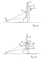
- Fig. 1 shows a wind turbine with tower 4 and nacelle 5 and two rotor blades 6 and 7.
- a non-contact distance measuring system 3 aligned with a first measuring point 1 and a second measuring point 2, which are being swept by the rotor blade 6.
- the rotor blades 6 and 7 are rotated so far that the measuring points 1, 2 are then swept by the rotor blade 7.
- Fig. 2 shows a wind turbine that in Fig. 1 However, with a arranged about 100 m in front of the wind turbine measuring system 3, which is aligned to a first measuring point 1 and to a second measuring point. 2
- Fig. 3 shows a view of a rotor blade 6 with indicated by dashed lines profile lines 8 and 9. These profile lines 8 and 9 are slightly curved over the rotor blade 6. This is because the rotor blade 6 rotates in a circle around the hub, while the measuring points are fixed in place ,
- Fig. 4a shows a wind turbine as in Fig. 1 and 2 , but with two non-contact measuring systems 3, each aligned with a first measuring point 1 and a second measuring point 2.
- the non-contact measuring system 3 which is arranged on the nacelle 5, oriented upward, while the non-contact measuring system 3, before the system is positioned at the bottom of the plane of rotation.
- Fig. 4b shows a wind turbine with tower 4 with non-contact distance measuring system 3.
- the non-contact distance measuring system 3 is aligned to two measuring points 1, 2. If no rotor blade 6, 7 obstructs the view of the tower 4, the contactless distance measuring system 3 measures the tower 4 at the tower measuring points 10. As a result, the inclination of the tower and the distance between the tower 4 and the contactless distance measuring system 3 can be determined.
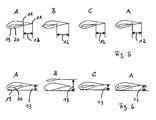
- Fig. 5 shows prepared measurement data of a non-contact distance measuring system. Shown are profile data for the rotor blades A, B, C and once again for the rotor blade A. The rotor blades A, B, C, A have passed through the corresponding measuring points one after the other and two profile lines 19, 20 of each rotor blade were received. These are shown superimposed here and is the distance of the trailing edge 11 of the individual profile lines 19, 20. This is the edgewise bending 12. It can be seen that they look very similar to the rotor blades A, B, A. Only rotor blade B falls clearly out of the frame. It can be seen that the rotor blade B deviates significantly in its rigidity or its arrangement in the rotor.
- Fig. 6 again shows in each case two profile lines 19, 20 of the rotor blades A, B, C, A, and it is the maximum tread depth 13 is characterized, which provides information about the flapwise bending.
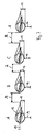
- Fig. 7 shows in each case three profile lines of the rotor blades A, B, C, A.
- Darin is a circle 15 to the calculated pitch axis. Furthermore drawn in are the positioning lines of the individual profiles. An angle of attack or pitch 17 has been drawn.
- the graduation 14 as well as the maximum tread depth 13 and a distance 16 to a predefined point / a predefined plane were identified.
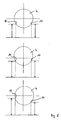
- Fig. 8 shows three views of a cross section through a tower with dashed lines of measurement, which impinge on tower measurement points 10. Also marked is a cross in the tower cross section, the indicates the rest position of the tower. In the upper figure, the tower is in the rest position. Both tower measuring points 10 have the same distance to the distance measuring device. In the middle picture of the Fig. 8 the tower is moved away from the rangefinder. As a result, the tower measuring points 10 have shifted to the rear, which can be detected.
- Fig. 9 shows a tower cross-section through a tower 4 with a rest position indicating cross as in Fig. 8 ,
- the first profile line 19 was used for the measurement
- the second profile line 20 was used for the measurement
- the absolute distance 16 and the distance between the rear edge 11 and the same reference point / plane are indicated as well as the profile depth of the respective profile.
- Fig. 10 shows measured values over a profile line via a rotor blade. Numerous revolutions of the rotor at one measuring point were used to record numerous profiles over the profile line and display them together. Shown is on the horizontal axis, the extension of the rotor blade in the plane of rotation in the direction of rotation, ie the profile line, and on the vertical axis, the distance of the surface of the rotor blade to the distance measuring system, so the profile. Before further analysis, it is advisable to perform an averaging via statistical methods. In the simplest case, the arithmetic mean of the distance is calculated at each point of the profile line.
Landscapes
- Engineering & Computer Science (AREA)
- Life Sciences & Earth Sciences (AREA)
- Sustainable Development (AREA)
- Sustainable Energy (AREA)
- Chemical & Material Sciences (AREA)
- Combustion & Propulsion (AREA)
- Mechanical Engineering (AREA)
- General Engineering & Computer Science (AREA)
- Physics & Mathematics (AREA)
- Fluid Mechanics (AREA)
- Wind Motors (AREA)
Claims (10)
- Procédé de mesure pour contrôler et/ou optimiser des installations d'énergie éolienne, comportant au moins une pale de rotor (6, 7) de forme allongée et montée sur un moyeu, le procédé consistant à :a. aligner un système (3) de mesure de distance sans contact adapté pour l'enregistrement, différé de 200 ms au maximum, d'au moins deux distances (16) à différents points, sur au moins deux points de mesure (1, 2) qui sont balayés par ladite au moins une pale de rotor (6, 7) et pour lesquels les distances (16) jusqu'au moyeu sont différentes ; etb. établir au moins deux profils (19, 20) à l'aide de ladite au moins une pale de rotor (6, 7) le long d'une ligne de profil (8, 9) respective, dans lequel lesdites au moins deux lignes de profil (8, 9) passent au-dessus des points de la pale de rotor (6, 7) qui balaient lesdits au moins deux points de mesure (1, 2).
- Procédé de mesure selon la revendication 1, consistant en outre à déterminer au moins une flexion, une raideur et/ou une torsion (12) de ladite au moins une pale de rotor (6, 7) sur base desdits au moins deux profils (19, 20).
- Procédé de mesure selon l'une des revendications précédentes, dans lequel la flexion (12) de ladite au moins une pale de rotor (6, 7) dans le plan du rotor et/ou hors du plan du rotor est établie entre lesdits au moins deux profils (19, 20).
- Procédé de mesure selon l'une des revendications précédentes, dans lequel la torsion est établie entre lesdits au moins deux profils (19, 20).
- Procédé de mesure selon l'une des revendications précédentes, dans lequel l'axe de tangage de la pale de rotor (6, 7) est établi sur base d'au moins un profil (19, 20).
- Procédé de mesure selon l'une des revendications précédentes, dans lequel l'angle de conicité de ladite au moins une pale de rotor (6, 7) est établi.
- Procédé de mesure selon l'une des revendications précédentes, dans lequel l'installation d'énergie éolienne comporte au moins deux pales de rotor (6, 7) et l'espacement (14), en particulier l'écart par rapport à un espacement (14) prévu, est établi.
- Procédé de mesure selon l'une des revendications précédentes, dans lequel l'installation d'énergie éolienne comporte une nacelle (5), et le système (3) de mesure de distance est positionné sur la nacelle (5) et mesure aussi en particulier les vibrations du mât.
- Procédé de mesure selon l'une des revendications 1 à 7, dans lequel le système (3) de mesure de distance est positionné à distance de l'installation d'énergie éolienne, et dans lequel la distance (16) du système (3) de mesure de distance jusqu'au moyeu et/ou jusqu'à un point du mât (10) ainsi que l'inclinaison du mât (4) sont en particulier établies.
- Installation d'énergie éolienne comportant au moins une pale de rotor (6, 7) de forme allongée montée sur un moyeu et comprenant un système de mesure pour contrôler et/ou optimiser l'installation d'énergie éolienne, comportant un système (3) de mesure de distance sans contact,a. comprenant un moyen d'alignement pour aligner sur au moins deux points de mesure (1, 2) à des distances (16) différentes jusqu'au moyeu, qui sont balayés par ladite au moins une pale de rotor (6, 7), etb. adapté à l'enregistrement simultané d'au moins deux profils (19, 20) sur ladite au moins une pale de rotor (6, 7) le long d'une ligne (8, 9) de profil respective par l'enregistrement, différé de 200 ms au maximum, de distances (16) auxdits au moins deux points de mesure (1, 2), dans laquelle lesdites au moins deux lignes de profil (8, 9) passent des points de la pale de rotor (6, 7) qui balaient lesdits au moins deux points de mesure (1, 2).
Applications Claiming Priority (2)
| Application Number | Priority Date | Filing Date | Title |
|---|---|---|---|
| DE102010024532A DE102010024532B4 (de) | 2010-06-21 | 2010-06-21 | Messverfahren zur Kontrolle und/oder Optimierung von Windenergieanlagen mit einem berührungslosen Abstandsmesssystem |
| PCT/EP2011/060241 WO2011161058A1 (fr) | 2010-06-21 | 2011-06-20 | Procédé de mesure pour le contrôle et/ou l'optimisation d'éoliennes grâce à un système de mesure de distance sans contact |
Publications (2)
| Publication Number | Publication Date |
|---|---|
| EP2582970A1 EP2582970A1 (fr) | 2013-04-24 |
| EP2582970B1 true EP2582970B1 (fr) | 2014-04-02 |
Family
ID=44546346
Family Applications (1)
| Application Number | Title | Priority Date | Filing Date |
|---|---|---|---|
| EP11735609.7A Active EP2582970B1 (fr) | 2010-06-21 | 2011-06-20 | Procédé de mesure pour le contrôle et/ou l'optimisation d'éoliennes grâce à un système de mesure de distance sans contact |
Country Status (4)
| Country | Link |
|---|---|
| EP (1) | EP2582970B1 (fr) |
| DE (1) | DE102010024532B4 (fr) |
| ES (1) | ES2468917T3 (fr) |
| WO (1) | WO2011161058A1 (fr) |
Families Citing this family (9)
| Publication number | Priority date | Publication date | Assignee | Title |
|---|---|---|---|---|
| DE102013201163A1 (de) * | 2013-01-24 | 2014-08-07 | Wobben Properties Gmbh | Verfahren zum Ausmessen eines Rotorblattwinkels |
| EP2873854A1 (fr) * | 2013-11-14 | 2015-05-20 | Siemens Aktiengesellschaft | Procédé pour déterminer une distance entre une paroi de tour et une pale d'éolienne |
| DE102015121981A1 (de) * | 2015-12-16 | 2017-06-22 | fos4X GmbH | Verfahren und Vorrichtung zum Betreiben einer Windkraftanlage |
| CN106286152B (zh) * | 2016-09-14 | 2018-12-04 | 北京金风科创风电设备有限公司 | 风力发电机组的叶片状态监测装置及监测方法 |
| CN106289114A (zh) * | 2016-10-19 | 2017-01-04 | 吴尧增 | 一种间接式风机转子几何参数测量及性能优化的方法 |
| DK3732369T3 (da) * | 2017-12-29 | 2023-07-10 | Windcomp Gmbh | Fremgangsmåde til udmåling af ubalancer i vindmøllerotorer |
| CN111102940B (zh) * | 2018-10-29 | 2022-07-05 | 北京金风科创风电设备有限公司 | 叶片桨距角偏差的检测方法、装置、存储介质及系统 |
| CN113107784B (zh) * | 2021-04-08 | 2022-05-17 | 中国华能集团清洁能源技术研究院有限公司 | 风电机组叶片角度的激光校正方法、装置、设备及介质 |
| CN113153656B (zh) * | 2021-05-26 | 2024-04-19 | 三一重能股份有限公司 | 一种风机的塔架净空监测系统及监测方法 |
Family Cites Families (4)
| Publication number | Priority date | Publication date | Assignee | Title |
|---|---|---|---|---|
| DE10032314C1 (de) * | 2000-07-04 | 2001-12-13 | Aloys Wobben | Verfahren zur Bestimmung des Winkels eines Rotorblatts einer Windenergieanlage |
| DE102005048805A1 (de) * | 2005-10-10 | 2007-04-12 | Daubner & Stommel GbR Bau-Werk-Planung (vertretungsberechtigter Gesellschafter: Matthias Stommel, 27777 Ganderkesee) | Verfahren zum Betreiben einer Windenergieanlage |
| DE102006054667B4 (de) * | 2006-11-17 | 2011-02-17 | Windcomp Gmbh | Kollisionswarnsystem für eine Windenergieanlage |
| DE102008013392B4 (de) * | 2008-03-10 | 2013-02-07 | Windcomp Gmbh | Verfahren zum Erfassen des Spurlaufes der Rotorblätter einer Windkraftanlage |
-
2010
- 2010-06-21 DE DE102010024532A patent/DE102010024532B4/de not_active Revoked
-
2011
- 2011-06-20 WO PCT/EP2011/060241 patent/WO2011161058A1/fr not_active Ceased
- 2011-06-20 EP EP11735609.7A patent/EP2582970B1/fr active Active
- 2011-06-20 ES ES11735609.7T patent/ES2468917T3/es active Active
Also Published As
| Publication number | Publication date |
|---|---|
| ES2468917T3 (es) | 2014-06-17 |
| EP2582970A1 (fr) | 2013-04-24 |
| DE102010024532B4 (de) | 2012-04-12 |
| DE102010024532A1 (de) | 2011-12-22 |
| WO2011161058A1 (fr) | 2011-12-29 |
Similar Documents
| Publication | Publication Date | Title |
|---|---|---|
| EP2582970B1 (fr) | Procédé de mesure pour le contrôle et/ou l'optimisation d'éoliennes grâce à un système de mesure de distance sans contact | |
| EP2215354B1 (fr) | Procédé et système de mesure de la déviation d'un élément creux d'une éolienne par rapport à une position normale | |
| EP2337950B1 (fr) | Profil d'une pale de rotor et pale de rotor d'une éolienne | |
| EP2582972B1 (fr) | Procédé et dispositif empêchant une oscillation transversale d'une éolienne | |
| EP1994280B1 (fr) | Système d'avertissement de risque de collision destiné à une éolienne | |
| EP3913215B1 (fr) | Procédé de mesure de l'angle d'incidence d'une pale de rotor | |
| EP3732369B1 (fr) | Procédé servant à mesurer des balourds de rotors d'éolienne | |
| WO2013034235A1 (fr) | Procédé et dispositif pour déterminer une erreur d'angle de lacet d'une éolienne, et éolienne correspondante | |
| DE602004001726T2 (de) | Windkraftanlage mit waagerechter Welle und Verfahren zur Messung des Aufwärtsströmungswinkels | |
| EP2715117A1 (fr) | Pale courbé du rotor d'une eolienne | |
| EP3704374B1 (fr) | Élément de tourbillonnement et procédé pour fabriquer un élément de tourbillonnement | |
| DE102008031484B4 (de) | Verfahren zur Ermittlung und Nachjustierung des relativen Flügeleinstellwinkels an Windenergieanlagen mit horizontalen Antriebsachsen | |
| DE102008013392B4 (de) | Verfahren zum Erfassen des Spurlaufes der Rotorblätter einer Windkraftanlage | |
| EP3824176B1 (fr) | Pale de rotor pour éolienne et éolienne | |
| DE202008006307U1 (de) | Flanschstück und Turm für eine Windenergieanlage | |
| DE102013103150A1 (de) | Verfahren zum Ermitteln eines Anstellwinkels | |
| EP3553311A1 (fr) | Dispositif et procédé de commande d'une éolienne | |
| EP4632222A1 (fr) | Procédé d'étalonnage d'un dispositif de mesure d'une éolienne | |
| EP4671535A1 (fr) | Procédé de validation d'une éolienne | |
| DE102013007744A1 (de) | Windkraftanlage und Verfahren | |
| DE102008032196A1 (de) | Überwachung der Rotorblattdurchbiegung in Abhängigkeit der generierten Leistung und/oder Windlast |
Legal Events
| Date | Code | Title | Description |
|---|---|---|---|
| PUAI | Public reference made under article 153(3) epc to a published international application that has entered the european phase |
Free format text: ORIGINAL CODE: 0009012 |
|
| 17P | Request for examination filed |
Effective date: 20121214 |
|
| AK | Designated contracting states |
Kind code of ref document: A1 Designated state(s): AL AT BE BG CH CY CZ DE DK EE ES FI FR GB GR HR HU IE IS IT LI LT LU LV MC MK MT NL NO PL PT RO RS SE SI SK SM TR |
|
| DAX | Request for extension of the european patent (deleted) | ||
| GRAP | Despatch of communication of intention to grant a patent |
Free format text: ORIGINAL CODE: EPIDOSNIGR1 |
|
| GRAS | Grant fee paid |
Free format text: ORIGINAL CODE: EPIDOSNIGR3 |
|
| GRAA | (expected) grant |
Free format text: ORIGINAL CODE: 0009210 |
|
| INTG | Intention to grant announced |
Effective date: 20140213 |
|
| AK | Designated contracting states |
Kind code of ref document: B1 Designated state(s): AL AT BE BG CH CY CZ DE DK EE ES FI FR GB GR HR HU IE IS IT LI LT LU LV MC MK MT NL NO PL PT RO RS SE SI SK SM TR |
|
| REG | Reference to a national code |
Ref country code: GB Ref legal event code: FG4D Free format text: NOT ENGLISH |
|
| REG | Reference to a national code |
Ref country code: AT Ref legal event code: REF Ref document number: 660301 Country of ref document: AT Kind code of ref document: T Effective date: 20140415 Ref country code: CH Ref legal event code: EP |
|
| REG | Reference to a national code |
Ref country code: IE Ref legal event code: FG4D Free format text: LANGUAGE OF EP DOCUMENT: GERMAN |
|
| REG | Reference to a national code |
Ref country code: DE Ref legal event code: R096 Ref document number: 502011002627 Country of ref document: DE Effective date: 20140515 |
|
| REG | Reference to a national code |
Ref country code: ES Ref legal event code: FG2A Ref document number: 2468917 Country of ref document: ES Kind code of ref document: T3 Effective date: 20140617 |
|
| RAP2 | Party data changed (patent owner data changed or rights of a patent transferred) |
Owner name: WINDCOMP GMBH |
|
| REG | Reference to a national code |
Ref country code: NL Ref legal event code: VDEP Effective date: 20140402 |
|
| REG | Reference to a national code |
Ref country code: LT Ref legal event code: MG4D |
|
| PG25 | Lapsed in a contracting state [announced via postgrant information from national office to epo] |
Ref country code: BG Free format text: LAPSE BECAUSE OF FAILURE TO SUBMIT A TRANSLATION OF THE DESCRIPTION OR TO PAY THE FEE WITHIN THE PRESCRIBED TIME-LIMIT Effective date: 20140702 Ref country code: GR Free format text: LAPSE BECAUSE OF FAILURE TO SUBMIT A TRANSLATION OF THE DESCRIPTION OR TO PAY THE FEE WITHIN THE PRESCRIBED TIME-LIMIT Effective date: 20140703 Ref country code: IS Free format text: LAPSE BECAUSE OF FAILURE TO SUBMIT A TRANSLATION OF THE DESCRIPTION OR TO PAY THE FEE WITHIN THE PRESCRIBED TIME-LIMIT Effective date: 20140802 Ref country code: CZ Free format text: LAPSE BECAUSE OF FAILURE TO SUBMIT A TRANSLATION OF THE DESCRIPTION OR TO PAY THE FEE WITHIN THE PRESCRIBED TIME-LIMIT Effective date: 20140402 Ref country code: NL Free format text: LAPSE BECAUSE OF FAILURE TO SUBMIT A TRANSLATION OF THE DESCRIPTION OR TO PAY THE FEE WITHIN THE PRESCRIBED TIME-LIMIT Effective date: 20140402 Ref country code: NO Free format text: LAPSE BECAUSE OF FAILURE TO SUBMIT A TRANSLATION OF THE DESCRIPTION OR TO PAY THE FEE WITHIN THE PRESCRIBED TIME-LIMIT Effective date: 20140702 Ref country code: FI Free format text: LAPSE BECAUSE OF FAILURE TO SUBMIT A TRANSLATION OF THE DESCRIPTION OR TO PAY THE FEE WITHIN THE PRESCRIBED TIME-LIMIT Effective date: 20140402 Ref country code: LT Free format text: LAPSE BECAUSE OF FAILURE TO SUBMIT A TRANSLATION OF THE DESCRIPTION OR TO PAY THE FEE WITHIN THE PRESCRIBED TIME-LIMIT Effective date: 20140402 Ref country code: CY Free format text: LAPSE BECAUSE OF FAILURE TO SUBMIT A TRANSLATION OF THE DESCRIPTION OR TO PAY THE FEE WITHIN THE PRESCRIBED TIME-LIMIT Effective date: 20140402 |
|
| PG25 | Lapsed in a contracting state [announced via postgrant information from national office to epo] |
Ref country code: HR Free format text: LAPSE BECAUSE OF FAILURE TO SUBMIT A TRANSLATION OF THE DESCRIPTION OR TO PAY THE FEE WITHIN THE PRESCRIBED TIME-LIMIT Effective date: 20140402 Ref country code: RS Free format text: LAPSE BECAUSE OF FAILURE TO SUBMIT A TRANSLATION OF THE DESCRIPTION OR TO PAY THE FEE WITHIN THE PRESCRIBED TIME-LIMIT Effective date: 20140402 Ref country code: PL Free format text: LAPSE BECAUSE OF FAILURE TO SUBMIT A TRANSLATION OF THE DESCRIPTION OR TO PAY THE FEE WITHIN THE PRESCRIBED TIME-LIMIT Effective date: 20140402 Ref country code: SE Free format text: LAPSE BECAUSE OF FAILURE TO SUBMIT A TRANSLATION OF THE DESCRIPTION OR TO PAY THE FEE WITHIN THE PRESCRIBED TIME-LIMIT Effective date: 20140402 Ref country code: LV Free format text: LAPSE BECAUSE OF FAILURE TO SUBMIT A TRANSLATION OF THE DESCRIPTION OR TO PAY THE FEE WITHIN THE PRESCRIBED TIME-LIMIT Effective date: 20140402 |
|
| PG25 | Lapsed in a contracting state [announced via postgrant information from national office to epo] |
Ref country code: PT Free format text: LAPSE BECAUSE OF FAILURE TO SUBMIT A TRANSLATION OF THE DESCRIPTION OR TO PAY THE FEE WITHIN THE PRESCRIBED TIME-LIMIT Effective date: 20140804 |
|
| REG | Reference to a national code |
Ref country code: DE Ref legal event code: R026 Ref document number: 502011002627 Country of ref document: DE |
|
| PLBI | Opposition filed |
Free format text: ORIGINAL CODE: 0009260 |
|
| PG25 | Lapsed in a contracting state [announced via postgrant information from national office to epo] |
Ref country code: EE Free format text: LAPSE BECAUSE OF FAILURE TO SUBMIT A TRANSLATION OF THE DESCRIPTION OR TO PAY THE FEE WITHIN THE PRESCRIBED TIME-LIMIT Effective date: 20140402 Ref country code: SK Free format text: LAPSE BECAUSE OF FAILURE TO SUBMIT A TRANSLATION OF THE DESCRIPTION OR TO PAY THE FEE WITHIN THE PRESCRIBED TIME-LIMIT Effective date: 20140402 Ref country code: LU Free format text: LAPSE BECAUSE OF FAILURE TO SUBMIT A TRANSLATION OF THE DESCRIPTION OR TO PAY THE FEE WITHIN THE PRESCRIBED TIME-LIMIT Effective date: 20140620 Ref country code: RO Free format text: LAPSE BECAUSE OF FAILURE TO SUBMIT A TRANSLATION OF THE DESCRIPTION OR TO PAY THE FEE WITHIN THE PRESCRIBED TIME-LIMIT Effective date: 20140402 Ref country code: DK Free format text: LAPSE BECAUSE OF FAILURE TO SUBMIT A TRANSLATION OF THE DESCRIPTION OR TO PAY THE FEE WITHIN THE PRESCRIBED TIME-LIMIT Effective date: 20140402 Ref country code: MC Free format text: LAPSE BECAUSE OF FAILURE TO SUBMIT A TRANSLATION OF THE DESCRIPTION OR TO PAY THE FEE WITHIN THE PRESCRIBED TIME-LIMIT Effective date: 20140402 |
|
| REG | Reference to a national code |
Ref country code: CH Ref legal event code: PL |
|
| PLAX | Notice of opposition and request to file observation + time limit sent |
Free format text: ORIGINAL CODE: EPIDOSNOBS2 |
|
| 26 | Opposition filed |
Opponent name: ENERCON GMBH Effective date: 20150105 |
|
| PG25 | Lapsed in a contracting state [announced via postgrant information from national office to epo] |
Ref country code: RS Free format text: LAPSE BECAUSE OF FAILURE TO SUBMIT A TRANSLATION OF THE DESCRIPTION OR TO PAY THE FEE WITHIN THE PRESCRIBED TIME-LIMIT Effective date: 20140716 |
|
| REG | Reference to a national code |
Ref country code: DE Ref legal event code: R026 Ref document number: 502011002627 Country of ref document: DE Effective date: 20150105 |
|
| REG | Reference to a national code |
Ref country code: IE Ref legal event code: MM4A |
|
| PLBP | Opposition withdrawn |
Free format text: ORIGINAL CODE: 0009264 |
|
| PG25 | Lapsed in a contracting state [announced via postgrant information from national office to epo] |
Ref country code: IE Free format text: LAPSE BECAUSE OF NON-PAYMENT OF DUE FEES Effective date: 20140620 Ref country code: LI Free format text: LAPSE BECAUSE OF NON-PAYMENT OF DUE FEES Effective date: 20140630 Ref country code: CH Free format text: LAPSE BECAUSE OF NON-PAYMENT OF DUE FEES Effective date: 20140630 |
|
| REG | Reference to a national code |
Ref country code: FR Ref legal event code: PLFP Year of fee payment: 5 |
|
| PG25 | Lapsed in a contracting state [announced via postgrant information from national office to epo] |
Ref country code: SI Free format text: LAPSE BECAUSE OF FAILURE TO SUBMIT A TRANSLATION OF THE DESCRIPTION OR TO PAY THE FEE WITHIN THE PRESCRIBED TIME-LIMIT Effective date: 20140402 |
|
| PLBD | Termination of opposition procedure: decision despatched |
Free format text: ORIGINAL CODE: EPIDOSNOPC1 |
|
| REG | Reference to a national code |
Ref country code: DE Ref legal event code: R100 Ref document number: 502011002627 Country of ref document: DE |
|
| PG25 | Lapsed in a contracting state [announced via postgrant information from national office to epo] |
Ref country code: MT Free format text: LAPSE BECAUSE OF FAILURE TO SUBMIT A TRANSLATION OF THE DESCRIPTION OR TO PAY THE FEE WITHIN THE PRESCRIBED TIME-LIMIT Effective date: 20140402 |
|
| PG25 | Lapsed in a contracting state [announced via postgrant information from national office to epo] |
Ref country code: SM Free format text: LAPSE BECAUSE OF FAILURE TO SUBMIT A TRANSLATION OF THE DESCRIPTION OR TO PAY THE FEE WITHIN THE PRESCRIBED TIME-LIMIT Effective date: 20140402 |
|
| PLBM | Termination of opposition procedure: date of legal effect published |
Free format text: ORIGINAL CODE: 0009276 |
|
| STAA | Information on the status of an ep patent application or granted ep patent |
Free format text: STATUS: OPPOSITION PROCEDURE CLOSED |
|
| 27C | Opposition proceedings terminated |
Effective date: 20160123 |
|
| REG | Reference to a national code |
Ref country code: FR Ref legal event code: PLFP Year of fee payment: 6 |
|
| PG25 | Lapsed in a contracting state [announced via postgrant information from national office to epo] |
Ref country code: HU Free format text: LAPSE BECAUSE OF FAILURE TO SUBMIT A TRANSLATION OF THE DESCRIPTION OR TO PAY THE FEE WITHIN THE PRESCRIBED TIME-LIMIT; INVALID AB INITIO Effective date: 20110620 Ref country code: TR Free format text: LAPSE BECAUSE OF FAILURE TO SUBMIT A TRANSLATION OF THE DESCRIPTION OR TO PAY THE FEE WITHIN THE PRESCRIBED TIME-LIMIT Effective date: 20140402 Ref country code: BE Free format text: LAPSE BECAUSE OF FAILURE TO SUBMIT A TRANSLATION OF THE DESCRIPTION OR TO PAY THE FEE WITHIN THE PRESCRIBED TIME-LIMIT Effective date: 20140630 |
|
| REG | Reference to a national code |
Ref country code: FR Ref legal event code: PLFP Year of fee payment: 7 |
|
| REG | Reference to a national code |
Ref country code: AT Ref legal event code: MM01 Ref document number: 660301 Country of ref document: AT Kind code of ref document: T Effective date: 20160620 |
|
| PG25 | Lapsed in a contracting state [announced via postgrant information from national office to epo] |
Ref country code: AT Free format text: LAPSE BECAUSE OF NON-PAYMENT OF DUE FEES Effective date: 20160620 |
|
| REG | Reference to a national code |
Ref country code: FR Ref legal event code: PLFP Year of fee payment: 8 |
|
| PG25 | Lapsed in a contracting state [announced via postgrant information from national office to epo] |
Ref country code: MK Free format text: LAPSE BECAUSE OF FAILURE TO SUBMIT A TRANSLATION OF THE DESCRIPTION OR TO PAY THE FEE WITHIN THE PRESCRIBED TIME-LIMIT Effective date: 20140402 |
|
| PG25 | Lapsed in a contracting state [announced via postgrant information from national office to epo] |
Ref country code: AL Free format text: LAPSE BECAUSE OF FAILURE TO SUBMIT A TRANSLATION OF THE DESCRIPTION OR TO PAY THE FEE WITHIN THE PRESCRIBED TIME-LIMIT Effective date: 20140402 |
|
| PGFP | Annual fee paid to national office [announced via postgrant information from national office to epo] |
Ref country code: ES Payment date: 20250917 Year of fee payment: 15 |
|
| PGFP | Annual fee paid to national office [announced via postgrant information from national office to epo] |
Ref country code: DE Payment date: 20250828 Year of fee payment: 15 |
|
| PGFP | Annual fee paid to national office [announced via postgrant information from national office to epo] |
Ref country code: GB Payment date: 20250829 Year of fee payment: 15 |
|
| PGFP | Annual fee paid to national office [announced via postgrant information from national office to epo] |
Ref country code: FR Payment date: 20250924 Year of fee payment: 15 |
|
| PGFP | Annual fee paid to national office [announced via postgrant information from national office to epo] |
Ref country code: IT Payment date: 20250930 Year of fee payment: 15 |