EP2583246B1 - Method and system of automatic determination of geometric elements characterizing a bone deformation from 3d image - Google Patents
Method and system of automatic determination of geometric elements characterizing a bone deformation from 3d image Download PDFInfo
- Publication number
- EP2583246B1 EP2583246B1 EP11768077.7A EP11768077A EP2583246B1 EP 2583246 B1 EP2583246 B1 EP 2583246B1 EP 11768077 A EP11768077 A EP 11768077A EP 2583246 B1 EP2583246 B1 EP 2583246B1
- Authority
- EP
- European Patent Office
- Prior art keywords
- head
- neck
- bone
- determining
- curve
- Prior art date
- Legal status (The legal status is an assumption and is not a legal conclusion. Google has not performed a legal analysis and makes no representation as to the accuracy of the status listed.)
- Not-in-force
Links
Images




Classifications
-
- G—PHYSICS
- G06—COMPUTING OR CALCULATING; COUNTING
- G06T—IMAGE DATA PROCESSING OR GENERATION, IN GENERAL
- G06T7/00—Image analysis
- G06T7/0002—Inspection of images, e.g. flaw detection
- G06T7/0012—Biomedical image inspection
-
- G—PHYSICS
- G06—COMPUTING OR CALCULATING; COUNTING
- G06T—IMAGE DATA PROCESSING OR GENERATION, IN GENERAL
- G06T17/00—Three-dimensional [3D] modelling for computer graphics
-
- G—PHYSICS
- G06—COMPUTING OR CALCULATING; COUNTING
- G06T—IMAGE DATA PROCESSING OR GENERATION, IN GENERAL
- G06T19/00—Manipulating three-dimensional [3D] models or images for computer graphics
-
- G—PHYSICS
- G06—COMPUTING OR CALCULATING; COUNTING
- G06T—IMAGE DATA PROCESSING OR GENERATION, IN GENERAL
- G06T7/00—Image analysis
- G06T7/60—Analysis of geometric attributes
- G06T7/64—Analysis of geometric attributes of convexity or concavity
-
- A—HUMAN NECESSITIES
- A61—MEDICAL OR VETERINARY SCIENCE; HYGIENE
- A61B—DIAGNOSIS; SURGERY; IDENTIFICATION
- A61B34/00—Computer-aided surgery; Manipulators or robots specially adapted for use in surgery
- A61B34/10—Computer-aided planning, simulation or modelling of surgical operations
- A61B2034/101—Computer-aided simulation of surgical operations
- A61B2034/105—Modelling of the patient, e.g. for ligaments or bones
-
- A—HUMAN NECESSITIES
- A61—MEDICAL OR VETERINARY SCIENCE; HYGIENE
- A61B—DIAGNOSIS; SURGERY; IDENTIFICATION
- A61B90/00—Instruments, implements or accessories specially adapted for surgery or diagnosis and not covered by any of the groups A61B1/00 - A61B50/00, e.g. for luxation treatment or for protecting wound edges
- A61B90/06—Measuring instruments not otherwise provided for
- A61B2090/061—Measuring instruments not otherwise provided for for measuring dimensions, e.g. length
-
- G—PHYSICS
- G06—COMPUTING OR CALCULATING; COUNTING
- G06T—IMAGE DATA PROCESSING OR GENERATION, IN GENERAL
- G06T2207/00—Indexing scheme for image analysis or image enhancement
- G06T2207/10—Image acquisition modality
- G06T2207/10072—Tomographic images
-
- G—PHYSICS
- G06—COMPUTING OR CALCULATING; COUNTING
- G06T—IMAGE DATA PROCESSING OR GENERATION, IN GENERAL
- G06T2207/00—Indexing scheme for image analysis or image enhancement
- G06T2207/30—Subject of image; Context of image processing
- G06T2207/30004—Biomedical image processing
- G06T2207/30008—Bone
-
- G—PHYSICS
- G06—COMPUTING OR CALCULATING; COUNTING
- G06T—IMAGE DATA PROCESSING OR GENERATION, IN GENERAL
- G06T2219/00—Indexing scheme for manipulating 3D models or images for computer graphics
- G06T2219/012—Dimensioning, tolerancing
-
- Y—GENERAL TAGGING OF NEW TECHNOLOGICAL DEVELOPMENTS; GENERAL TAGGING OF CROSS-SECTIONAL TECHNOLOGIES SPANNING OVER SEVERAL SECTIONS OF THE IPC; TECHNICAL SUBJECTS COVERED BY FORMER USPC CROSS-REFERENCE ART COLLECTIONS [XRACs] AND DIGESTS
- Y10—TECHNICAL SUBJECTS COVERED BY FORMER USPC
- Y10S—TECHNICAL SUBJECTS COVERED BY FORMER USPC CROSS-REFERENCE ART COLLECTIONS [XRACs] AND DIGESTS
- Y10S128/00—Surgery
- Y10S128/92—Computer assisted medical diagnostics
- Y10S128/922—Computer assisted medical diagnostics including image analysis
-
- Y—GENERAL TAGGING OF NEW TECHNOLOGICAL DEVELOPMENTS; GENERAL TAGGING OF CROSS-SECTIONAL TECHNOLOGIES SPANNING OVER SEVERAL SECTIONS OF THE IPC; TECHNICAL SUBJECTS COVERED BY FORMER USPC CROSS-REFERENCE ART COLLECTIONS [XRACs] AND DIGESTS
- Y10—TECHNICAL SUBJECTS COVERED BY FORMER USPC
- Y10S—TECHNICAL SUBJECTS COVERED BY FORMER USPC CROSS-REFERENCE ART COLLECTIONS [XRACs] AND DIGESTS
- Y10S128/00—Surgery
- Y10S128/92—Computer assisted medical diagnostics
- Y10S128/923—Computer assisted medical diagnostics by comparison of patient data to other data
Definitions
- the invention relates to the field of computer assisted surgical planning, and more particularly to a method and a system for the characterization of a bone deformation from acquired 3D medical image.
- Femoro Acetabular Impingement is a pathology that can result from a decreased femoral head-neck offset (cam effect), an overgrowth of the bony acetabulum (pincer effect), excessive acetabular retroversion or excessive femoral anteversion, or a combination of these deformities.
- the cam impingement is generally characterized by a bone overgrowth located at the antero-superior aspect of the femur head-neck junction, which destructures the spherical shape of the femur head.
- the pincer impingement is generally characterized by an overcoverage located at the anterior aspect of the acetabulum rim.
- Standard radiographic X-rays are used for the initial diagnosis and then three dimensional (3D) Computed Tomography (CT) scans or Magnetic Resonance Imaging (MRI) exams are generally performed in case of suspected FAI pathology. It is known in the clinical literature to produce reformatted slices from 3D medical image volume, to create two dimensional (2D) image slices in different orientation in order to increase the chance of detecting bone deformation.
- CT Computed Tomography
- MRI Magnetic Resonance Imaging
- Another important measurement is the orientation of the femoral neck, especially the version of the neck which is measured relatively to the knee rotation axis. This measurement is usually performed by measuring independently the orientation of the posterior condyles and the neck orientation in axial slices of the 3D image volume, and then recomputing from these two measures, a femoral neck version.
- the final neck version measurement thus being a combination of two measurements, only taking two dimensions into account, not reflecting true 3D orientation.
- the specific problem addressed by the invention is the difficulty to characterize precisely in three-dimensional space and in a fast and reproducible manner the bone deformation to be treated surgically, from pre-operative 3D image of the patient.
- the invention provides a method for automatically determining, on a bone comprising a head portion contiguous to a neck portion, parameters for characterizing a bump deformation on the head-neck junction of the bone from acquired 3D medical image, according to the claims.
- Another object of the invention is a system for determining, on a bone comprising a head portion contiguous to a neck portion, parameters for characterizing a bump deformation on the head-neck junction of the bone from acquired 3D medical image, the system comprising a computer including a memory and a processing unit adapted to run a computer program, wherein said computer program comprises at least one algorithm applying the method of one of claims 1 to 11.
- Some critical anatomical elements are necessary to measure some specific anatomical characteristics of the proximal femur, such as the femoral neck version angle, and the amplitude of the head-neck junction bump deformation measured by the alpha angle, which participates in the characterization of the proximal femur deformity in Femoro Acetabular Impingement (FAI) pathology.
- FAI Femoro Acetabular Impingement
- the method is described by specifically addressing the femur but it can be extended to other bones of the human or animal body such as the humerus or other bones having a rotoid articulation.
- the general purpose of the invention is to determine from the 3D image of the bone, major parameters for characterizing a bump deformation on the head-neck junction of the bone, in a fast, precise and reproducible manner.
- the method detailed hereafter has to be understood as an algorithm implemented in the form of a software program on a processing unit.
- the head of the bone is assumed to have a spherical portion and the neck is assumed to have roughly a diabolo shape.
- the deformation of the bone consists in the formation of a bump at the head neck junction, generally in a location where there are repetitive collisions between the femur and the acetabulum during hip motion.
- the characterization of the anatomy is based on the measurement of the neck version angle, and the characterization of the deformation is based on the measurement of the alpha angle, in one or several 2D slices in the 3D image volume.
- the computations need to be based on the precise determination of the following reference anatomical elements: the femoral head sphere center and radius, the femoral neck axis, the clock face on the femoral head, and the knee rotation axis.
- the purpose of the invention is to describe a method of automatic and accurate determination of the characterization values of the femoral anatomy deformity very quickly, based on of those critical geometric elements from the 3D image.
- a 3D medical image examination of the patient is performed in order to provide a 3D image of the hip bones using a specific predefined protocol as initial input to the method.
- a computer tomography (CT) examination can be performed.
- CT computer tomography
- our method requires the acquisition of a few extra images at the level of the knee.
- the 3D image is represented by a stack of parallel 2D images, with known relative positions.
- the acquisition of the 3D image is a preliminary step that can be directly included in the method of the invention or carried out previously.
- the method is implemented as image processing software running on a standard computer.
- the user can interact with the software by a standard user interface medium like a mouse, touch screen or the like. Images are displayed on the monitor of the computer.
- the software is used to select and load the 3D image of the specific patient.
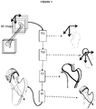
- the method contains successive steps, using as input the 3D image of the bone, and producing as output the indices characterizing the bump deformation of the head-neck junction of the bone.
- the first two steps PS1 and PS2 are preliminary steps necessary for the method of the invention but they are not in the scope of the invention itself. Therefore the first two steps are not described in full details, but only examples of their implementation and the resulting elements from these steps are described.
- the first preliminary step PS1 of the method consists in creating from the 3D medical image of the bone, a 3D surface model of the bone surface S as illustrated in Fig.2 .
- a thresholding process is used to determine an initial surface model by comparing each value of the 3D image point to a predefined threshold value in Hounsfield units representing cortical bone, and retaining points that have a value close to the threshold value, "close” generally meaning within a range of +10% and -10% from the threshold value. It generates multiples binary objects defining connected components in the space of the 3D image. Additional processing using well known mathematical morphology operators is applied to those binary objects to eliminate small connected components and to fill the inside of closed surfaces so that only the external surface of the bone remains.
- the generated surface model S is usually not perfect since the thresholding tends to merge the bone surface with adjacent bones and to create some defects in the surface. Those imperfections are due to many phenomena including the quality of image acquisition and reconstruction, but also to the poor quality of bone density in some pathological areas. Similar conventional methods such as the marching cube or the dividing cube can be applied to build a surface model of the bone.
- the surface of the bone reconstructed from the 3D image is referred to as the 3D surface model.
- the 3D surface model comprises different portions of anatomical surfaces, including the head surface and the neck surface.
- the next preliminary step PS2 starts by the identification in the 3D surface model a sphere S F fitting the spherical portion of the head of the bone as illustrated in Fig. 2 .
- sphere S F from fully manual identification of circles in at least two orthogonal 2D reformatted slices selected so as to pass through the head to fully automatic iterative methods, converging to the best fitting sphere, thus providing a 3D head center point H and a radius R.
- One example of a method for the determination of the sphere S F is to apply an iterative method based on the identification of an approximate head center point and an approximate radius, and then applying robust least-square fitting of a sphere to the 3D surface model points, starting from the approximate head center point and the approximate radius. The result is the determination of the head center point H and the radius R of the sphere S F .
- FIG. 3A and 3B One example of an option for the detection the neck axis AX is illustrated in Figs. 3A and 3B . It consists in applying an iterative method based on the identification of an approximate axis AX 0 passing through the head center H and then applying a minimization process in two orthogonal cross-sections of the 3D surface model passing through AX 0 . In each section, the process is to adjust the position of AX 0 in order to minimize the distances from AX 0 to the contours of the neck portion in the cross-section of the 3D surface model. As illustrating in Figs.
- the closest points A i and A' i of the contours of the neck portion on each side of the axis AX 0 are computed in both cross-sections.
- the minimization process consists in adjusting the position of AX 0 in both cross-sections in order to minimize the distance of the points A i and A' i to their respective orthogonal projection on AX 0 .
- the resulting axis is the neck axis AX.
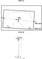
- a 3D mechanical femur coordinate system is constructed from the femur head center H, the knee center K and the knee transverse axis ML that joins the points M and L which are the medial and lateral epicondyles of the knee or that joins the most posterior points of the knee condyles.
- These last two anatomical elements are determined from 3D images acquired at the level of the knee joint as shown in Fig. 4A . From these images, the knee center point K is determined. It is easy to find the centroid of these images after appropriate thresholding and compute an initial knee center K0.
- a rectangular box is computed around K0 in the axial image plane containing K0, such box being adjusted to be the smallest in contact with surface points detected on the bone.
- the center of the rectangular box becomes the estimation of the knee center K1.
- the epicondyles points E1 and E2 can be automatically detected by searching for example the two most distant bone points in the rectangular box computed above, passing within a given range of the knee center point K1.
- Other algorithms can be used to detect the epicondylar axis.
- the knee center point K can be defined as the middle of the MLe segment.
- a Medio-Lateral axis that we can extract is the postero-condylar axis MLp. It can be extracted using iterative methods to search for the most posterior points in the axial images of the knee.
- the femur coordinate system is constructed as follows: its origin is centered on the femoral head center H, the X F axis is defined by the vector HK, the Z F axis is defined as the vector product of X F by ML, and the Y F axis is defined as the vector product of Z F by X F . It is then possible to measure the neck version angle, which is the neck axis orientation relatively to the ML axis in the axial plane of the femur coordinate system, which is an important element to be taken into account in the analysis of the whole case for decision of the surgical treatment.
- the 3D image referential it is possible to use directly the 3D image referential to orientate the 3D mechanical referential, though assuming the position of the patient during the exam can be controlled to meet expected mechanical orientation.
- the anatomical directions are defined from the axes of the 3D mechanical referential and of the neck as follows:
- the next step S3 of the method consists in mapping automatically on the 3D surface model of the head of the bone, a clock face referential system, which has clinical significance when addressing bones with a head portion.
- the clock face is a radial referential system representing 12 hours angular segments commonly used by surgeons to identify location of points on the femoral head surface.
- the clock face can be fully determined by determining the location of the 12 o'clock plane P12h. Successive rotations of this plane around the neck axis AX will then define the 1 o'clock, 2 o'clock, and followings, until 11 o'clock location.
- Fig. 5A and 5B the clock face is a radial referential system representing 12 hours angular segments commonly used by surgeons to identify location of points on the femoral head surface.
- the clock face can be fully determined by determining the location of the 12 o'clock plane P12h. Successive rotations of this plane around the neck axis AX will then define the 1 o'clock, 2 o'clock, and followings, until 11 o'clock location.
- our method consists in determining the position of the 12 o'clock plane P 12h , as the location of the most superior portion of the intersection line of the 3D surface model and the plane passing through the neck axis AX and the knee center point K determined by the method defined previously. It provides a fully automated determination of the clock face from the 3D image.
- the goal is to characterize the femur bump deformation by superimposing the 3D femoral head sphere S F and the femur 3D bone surface model in order to locate and quantify the 3D curve where the two surfaces intersect.
- the next step S4 of the method consists in determining automatically the 3D curve characterizing the head-neck junction of the bone.
- series of hemi-planes Pi passing through the head center H and around the neck axis AX are computed in the 3D image volume, as shown in Fig. 5B .
- Those hemi-planes Pi are identified by a clock index i, starting at 12 o'clock.
- hemi-planes Pi are computed every hour around the clock. But it could be also every half hour or even more precisely.
- One of the difficulty of this step is that the 3D surface model of the head neck junction represents an imperfect surface, and local small deviations generated by artifacts during the surface reconstruction can lead to an erroneous determination of the 3D curve.
- a femoral head apex point Ap is defined as the intersection point between the femoral neck axis AX and the circle Ci opposite to the neck.
- the point Mi is determined in the following manner: the closest point from the femoral head apex Ap which is lying on the contour FCi and which is lying outside the circle Ci, over a given threshold distance TD, and which neighbour M'i further down along the contour FCi in the direction of the neck is also lying outside the circle Ci .
- a threshold distance TD is generally set between 0.5mm and 1mm and it must be below 2mm to provide accurate results.
- the neighbour M'i along the contour FCi is generally considered up to a maximum distance of 2mm for Mi.
- This point Mi is considered as the head-neck junction point of the bone in the hemi-plane Pi.
- the process for detecting the point Mi complying with the above conditions is illustrated in Fig 7 and is carried out automatically in the following manner:
- a point Mij (wherein j is an integer greater than 1 of an index position of an angle between 0° and 180°) is following the contour of the femoral head in the direction of the neck. If a first point Mi1 lying outside the circle Ci is detected.However, if its distance from the border of the circle Ci is smaller than the threshold distance TD, Mi1 is discarded and the point Mij continues its path on the femoral head contour in the direction of the neck. If a next point Mi2 lying outside the circle Ci is detected, which distance from the border of the circle Ci is equal to or greater than the threshold distance TD, then its neighbour M'i2 on the contour of the femoral head in the direction of the neck is also tested.
- M'i2 is lying outside the circle Ci but its distance from the border of the circle Ci is smaller than the threshold distance, then Mi2 is also discarded and the point Mij continues its path on the femoral head contour in the direction of the neck. If a next point Mi3 lying outside the circle Ci is detected, which distance from the border of the circle Ci is equal or greater than the threshold distance TD, then its neighbour M'i3 on the contour of the femoral head in the direction of the neck is also tested. If M'i3 is lying outside the circle Ci at a distance from the border of the circle Ci greater than the threshold distance TD, then the point Mi3 is selected to be the point Mi searched for.
- This process avoids detecting small local bumps which might come from the imperfection of the reconstructed 3D surface model, and insures to take into account only the actual bump of the head-neck deformation when determining the 3D curve of the head-neck junction.
- the neighbour test described previously can also be performed in the orthogonal direction to the hemi-plane Pi, the neighbours being then located on the 3D surface model, on both sides of the contour FCi, thus reinforcing criteria for the detection of an actual bump in 3D and not only in 2D.
- the position of the detected point Mi in the hemi-plane Pi on the contour FCi can be further adjusted in order to comply with a continuity constraint with point Mi+1 and point Mi-1 respectively detected on the contours FCi+1 and FCi-1 in the hemi-planes Pi+1 and Pi-1.
- the position of the central point Mi in a triplet of contiguous points (Mi-1, Mi, Mi+1) for all points Mi by minimizing the sum SMi of the distances from Mi-1 to Mi, and Mi to Mi+1.
- the point Mi is therefore adjusted into the point Ni, where Ni is lying on the contour FCi, outside the circle Ci, within a distance less or equal to the threshold TD and such that the sum SNi of the distances from Mi-1 to Ni, and Ni to Mi+1 is smaller than SMi.
- the linking of the points Mi can be performed using straight linking segments between contiguous points Mi, thus creating a 3D pecked line.
- a minimal 3D curve can be determined by fitting a 3D spline curve of minimal length, interpolating contiguous Mi points.
- the 2D alpha angle ⁇ i which is a common index used for characterizing the femoral head-neck junction is automatically computed as the angle between the hemi-line from the femoral sphere center H and in the direction of the neck axis AX and the hemi- line from femoral sphere center H and the point Mi as shown in Fig 6 .
- the 3D curve passing through the Mi points is then referred to as the 3D alpha curve.
- a 3D alpha angle ⁇ 3D is determined as the maximum value amongst the 2D alpha angles ⁇ i.
- the corresponding point Mi determines the summit of the head-neck junction curve characterizing the bump deformation and is referred to as the maximum point Mmax and the corresponding clock index as the maximum index iMax.
- the maximum ⁇ 3D angle is a first parameter that characterizes the 3D bump by quantifying the "amount" of the bone deformity.
- the maximum clock index iMax is a second parameter that characterizes the 3D bump by giving its location on the clock face. The 3D alpha curve and the pair of indices ( ⁇ 3D, iMax) then fully characterize the femoral head-neck junction bump deformation. Together with the neck version measurement described previously, the parameters characterizing the bump will enable the surgeon to decide of the most appropriate surgical treatment.
- the advantage of the invention is the precise, and automatic determination of characteristic elements quantifying and locating the deformation of the nead-neck junction of a bone in a 3D image requiring the least possible input from user interaction. From the determination of these elements, it is then possible for surgeons to decide on the most appropriate surgical treatment. Usually those characterization measurements are performed manually by a radiologist, which takes time and efforts and is prone to human errors or inaccurate measurements, and potentially misleading the choice of surgical treatment. Our method provides then a fast and more reliable process to perform these measurements during the analysis of the pathology.
Landscapes
- Engineering & Computer Science (AREA)
- Physics & Mathematics (AREA)
- Theoretical Computer Science (AREA)
- General Physics & Mathematics (AREA)
- Computer Graphics (AREA)
- Computer Vision & Pattern Recognition (AREA)
- Software Systems (AREA)
- Geometry (AREA)
- Health & Medical Sciences (AREA)
- General Health & Medical Sciences (AREA)
- Medical Informatics (AREA)
- Nuclear Medicine, Radiotherapy & Molecular Imaging (AREA)
- Radiology & Medical Imaging (AREA)
- Quality & Reliability (AREA)
- General Engineering & Computer Science (AREA)
- Computer Hardware Design (AREA)
- Apparatus For Radiation Diagnosis (AREA)
- Measuring And Recording Apparatus For Diagnosis (AREA)
- Image Analysis (AREA)
Claims (11)
- Méthode pour déterminer automatiquement, sur un os comprenant une partie tête contiguë à une partie col, des paramètres pour caractériser une déformation de type bosse sur la jonction tête-col de l'os à partir d'une image médicale 3D acquise, la méthode comprenant les étapes suivantes :i) construction d'un modèle 3D surfacique de l'os à partir de l'image médicale 3D acquise ;ii) ajustement d'une sphère (SF) sur la partie sphérique de la tête de l'os ;iii) détermination d'un axe de col (AX) caractérisant la partie col de l'os ;iv) détermination à partir de l'axe de col, d'une référence de type cadran d'horloge sur la tête de l'os par rotation d'un plan autour de l'axe de col ;v) détermination d'une courbe 3D (1) sur le modèle 3D surfacique caractérisant la jonction tête-col de l'os ;vi) détermination, à partir de la courbe 3D (1), du sommet de la déformation de type bosse de la jonction tête-col de l'os, ledit sommet étant le point (Mmax) sur la courbe 3D (1) correspondant à l'angle maximal (α3D) parmi les angles (αi) entre la demi-droite issue du centre (H) de la sphère ajustée (SF) dans la direction de l'axe de col (AX) et la demi-droite reliant le centre (H) de la sphère ajustée (SF) et un point respectif (Mi) de la courbe 3D (1) ;vii) détermination, à partir dudit sommet de la déformation de type bosse, d'un premier et d'un second paramètre (α3D, iMax) caractérisant la déformation maximale de type bosse de la jonction tête-col de l'os, dans laquelle le premier paramètre (α3D) est l'angle maximal défini par un bloc de caractéristiques vi) et le second paramètre (iMax) est un indice d'horloge situant sur la référence de type cadran d'horloge le sommet de la déformation de type bosse.
- Méthode selon la revendication 1 dans laquelle l'étape de détermination de la référence de type cadran d'horloge est réalisée par un calcul automatique comprenant les étapes suivantes :i) détermination d'un demi-plan coronaire supérieur à 12 heures passant à travers l'axe de col de l'os ;ii) détermination sur la tête de l'os de l'indice à 12 heures à l'emplacement de l'intersection du demi-plan coronaire et du modèle 3D surfacique de l'os, au niveau de la partie la plus supérieure de la tête de l'os ;iii) détermination sur la tête de l'os des indices d'horloge successifs par rotation du demi-plan coronaire autour de l'axe de col pour chaque heure, l'indice d'heure actuel étant déterminé à l'emplacement de l'intersection du demi-plan mis en rotation actuel et du modèle 3D surfacique de l'os.
- Méthode selon la revendication 2 dans laquelle ledit demi-plan coronaire supérieur à 12 heures est déterminé à partir d'une partie supérieure d'un plan coronaire contenant l'axe de col et passant à travers un point central de genou défini à partir de l'image 3D de genou ; la partie supérieure du plan coronaire étant le demi-plan débutant au niveau de l'axe de col et s'étendant dans la direction opposée à partir du point central de genou.
- Méthode selon l'une des revendications 1 à 3, dans laquelle l'étape de détermination de la courbe 3D est réalisée par un calcul automatique comprenant les étapes suivantes :i) détermination d'un ensemble de demi-plans radiaux contenant l'axe de col et en rotation autour de l'axe de col sur la référence de type cadran d'horloge ;ii) détermination pour chaque demi-plan radial d'un point issu de l'apex de la sphère ajustée et se déplaçant dans la direction du col le long d'une courbe de contour de tête déterminée à partir de l'intersection du modèle 3D surfacique et du demi-plan radial ;iii) détermination de la première position du point se déplaçant le long de la courbe de contour de tête où il se situe en dehors d'un cercle déterminé par l'intersection de la sphère ajustée et du demi-plan radial, sur une distance seuil prédéfinie à partir du contour du cercle ; ce point définissant un point limite de jonction tête-col ;iv) détermination à partir de tous les demi-plans radiaux d'un ensemble de points limites 3D de jonction tête-col ;v) détermination d'une courbe 3D sur le modèle 3D surfacique de l'os en tant que courbe 3D optimale passant à travers l'ensemble de points d'intersection 3D ; la courbe 3D définissant la courbe 3D de jonction tête-col.
- Méthode selon la revendication 4 dans laquelle les demi-plans radiaux sont déterminés à intervalles angulaires réguliers, au moins pour chaque heure autour de la référence de type cadran d'horloge.
- Méthode selon l'une des revendications 4 ou 5 dans laquelle le seuil prédéfini est dans un intervalle de minimum 0,5 mm et maximum 2 mm.
- Méthode selon l'une des revendications 4 à 6, dans laquelle la détermination d'un point limite de jonction tête-col dans un demi-plan radial remplit en outre la condition que ses points voisins à une distance maximale de 2 mm plus bas le long de la courbe de contour de tête dans la direction du col se situent également en dehors du cercle sur la distance seuil.
- Méthode selon la revendication 7 dans laquelle la détermination de chaque point limite de jonction tête-col dans tous les demi-plans radiaux comprend en outre un ajustement de leur position à l'intérieur de la limite seuil, le long de leur courbe respective de contour de tête de façon à réduire au minimum la distance 3D relative de paires de points contiguës dans des triplets contigus de points limites 3D de jonction tête-col.
- Méthode selon l'une quelconque des revendications 4 à 8 dans laquelle ladite courbe optimale est déterminée par une ligne brisée 3D formée de segments de liaison droits reliant des points contigus dans l'ensemble de points limites 3D de jonction tête-col.
- Méthode selon l'une quelconque des revendications 4 à 8 dans laquelle ladite courbe optimale est déterminée par une courbe spline 3D de longueur minime interpolant les points contigus dans l'ensemble de points limites 3D de jonction tête-col.
- Système de détermination, sur un os comprenant une partie tête contiguë à une partie col, de paramètres pour caractériser une déformation de type bosse sur la jonction tête-col de l'os à partir d'une image médicale 3D acquise, le système comprenant un ordinateur incluant une mémoire et une unité de traitement adaptée pour exécuter un programme informatique, dans lequel ledit programme informatique comprend au moins un algorithme appliquant la méthode selon l'une des revendications 1 à 10.
Applications Claiming Priority (2)
| Application Number | Priority Date | Filing Date | Title |
|---|---|---|---|
| US35520610P | 2010-06-16 | 2010-06-16 | |
| PCT/IB2011/001687 WO2011158117A2 (fr) | 2010-06-16 | 2011-06-16 | Procédé et système de détermination automatique d'éléments géométriques caractérisant une déformation osseuse à partir d'une image tridimensionnelle |
Publications (2)
| Publication Number | Publication Date |
|---|---|
| EP2583246A2 EP2583246A2 (fr) | 2013-04-24 |
| EP2583246B1 true EP2583246B1 (fr) | 2019-01-30 |
Family
ID=44789507
Family Applications (1)
| Application Number | Title | Priority Date | Filing Date |
|---|---|---|---|
| EP11768077.7A Not-in-force EP2583246B1 (fr) | 2010-06-16 | 2011-06-16 | Method and system of automatic determination of geometric elements characterizing a bone deformation from 3d image |
Country Status (5)
| Country | Link |
|---|---|
| US (2) | US8923584B2 (fr) |
| EP (1) | EP2583246B1 (fr) |
| JP (1) | JP5845253B2 (fr) |
| AU (1) | AU2011266700B2 (fr) |
| WO (1) | WO2011158117A2 (fr) |
Families Citing this family (20)
| Publication number | Priority date | Publication date | Assignee | Title |
|---|---|---|---|---|
| FR2979815B1 (fr) * | 2011-09-14 | 2013-10-11 | Anatomic | Procede de determination d'une surface externe d'une partie femorale d'une prothese de genou |
| GB2532614B8 (en) | 2013-05-02 | 2020-07-08 | Hu Yangqiu | Surface and image integration for model evaluation and landmark determination |
| JP2016532475A (ja) * | 2013-10-08 | 2016-10-20 | スミス アンド ネフュー インコーポレーテッド | X線画像内で骨の形態学的関心領域を最適に可視化するための方法 |
| US10028649B2 (en) * | 2013-12-02 | 2018-07-24 | Welch Allyn, Inc. | Digital colposcope system |
| CN104622559B (zh) * | 2014-12-23 | 2017-03-15 | 河海大学常州校区 | 一种参数化股骨模板的构建方法 |
| CA3027964C (fr) | 2016-06-16 | 2021-05-25 | Medtech S.A. | Systeme robotise de resurfacage du conflit femoro-acetabulaire |
| US9978173B2 (en) * | 2016-07-27 | 2018-05-22 | Adobe Systems Incorporated | Generating views of three-dimensional models illustrating defects |
| EP3541270A4 (fr) * | 2016-11-18 | 2020-06-10 | Stryker Corp. | Procédé et appareil destinés au traitement d'une articulation, comprenant le traitement d'un conflit fémoro-acétabulaire de type came dans une articulation de la hanche et d'un conflit fémoro-acétabulaire de type pince dans une articulation de la hanche |
| US11033333B2 (en) * | 2017-04-06 | 2021-06-15 | Stryker European Holdings I, Llc | Plate selection user interface and design tool with database |
| US11464569B2 (en) | 2018-01-29 | 2022-10-11 | Stryker Corporation | Systems and methods for pre-operative visualization of a joint |
| US10820837B2 (en) * | 2018-04-09 | 2020-11-03 | Siemens Healthcare Gmbh | System and method for angle measurements using magnetic resonance images |
| US12502218B2 (en) | 2019-02-08 | 2025-12-23 | Stryker Corporation | Systems and methods for treating a joint |
| EP4065023B1 (fr) * | 2019-11-26 | 2025-12-17 | Howmedica Osteonics Corp. | Planification préopératoire et guidage peropératoire pour des procédures chirurgicales orthopédiques dans des cas de fragmentation osseuse |
| CN115942913B (zh) | 2020-02-21 | 2026-01-06 | 史赛克公司 | 用于在关节手术程序期间视觉引导骨去除的系统和方法 |
| WO2022133442A1 (fr) | 2020-12-15 | 2022-06-23 | Stryker Corporation | Systèmes et procédés pour générer un modèle tridimensionnel d'une articulation à partir d'images bidimensionnelles |
| US11794107B2 (en) * | 2020-12-30 | 2023-10-24 | Activision Publishing, Inc. | Systems and methods for improved collision detection in video games |
| CN115131380B (zh) * | 2022-03-03 | 2023-09-01 | 中国人民解放军总医院第四医学中心 | 骨骼组成部位的确定方法、装置、设备及存储介质 |
| CN115770034B (zh) * | 2022-11-16 | 2025-02-25 | 昆明市儿童医院 | 基于三维点云数据的胸骨变形检测方法及装置 |
| CN116712171B (zh) * | 2023-08-11 | 2023-11-03 | 北京维卓致远医疗科技发展有限责任公司 | 一种粗隆间骨折导航方法、设备及可存储介质 |
| CN116778022B (zh) * | 2023-08-24 | 2023-10-20 | 武汉大学 | 基于三维ct图像的股骨颈轴线自动定位方法、系统及设备 |
Family Cites Families (31)
| Publication number | Priority date | Publication date | Assignee | Title |
|---|---|---|---|---|
| US5880976A (en) | 1997-02-21 | 1999-03-09 | Carnegie Mellon University | Apparatus and method for facilitating the implantation of artificial components in joints |
| US6366357B1 (en) * | 1998-03-05 | 2002-04-02 | General Scanning, Inc. | Method and system for high speed measuring of microscopic targets |
| SE9802052L (sv) | 1998-04-01 | 1999-10-02 | Stig Lindequist | Förfarande och anordningar för håltagning och bestämning av riktning vid håltagning |
| SE9801168L (sv) | 1998-04-01 | 1999-07-12 | Stig Lindequist | Förfarande och anordning för bestämning av positionen hos fixeringsorgan vid höftledsfraktur |
| AU2001290887B2 (en) * | 2000-09-14 | 2006-06-08 | The Board Of Trustees Of The Leland Stanford Junior University | Assessing condition of a joint and cartilage loss |
| US7481780B2 (en) | 2001-12-11 | 2009-01-27 | ECOLE DE TECHNOLOGIE SUPéRIEURE | Method of calibration for the representation of knee kinematics and harness for use therewith |
| US6750974B2 (en) * | 2002-04-02 | 2004-06-15 | Gsi Lumonics Corporation | Method and system for 3D imaging of target regions |
| FR2841118B1 (fr) | 2002-06-20 | 2012-03-23 | Perception Raisonnement Action En Medecine | Determination de la position d'un appareil de radiographie ou de radioscopie |
| KR100507780B1 (ko) * | 2002-12-20 | 2005-08-17 | 한국전자통신연구원 | 고속 마커프리 모션 캡쳐 장치 및 방법 |
| US7103399B2 (en) * | 2003-09-08 | 2006-09-05 | Vanderbilt University | Apparatus and methods of cortical surface registration and deformation tracking for patient-to-image alignment in relation to image-guided surgery |
| US7519209B2 (en) * | 2004-06-23 | 2009-04-14 | Vanderbilt University | System and methods of organ segmentation and applications of same |
| US7327865B2 (en) * | 2004-06-30 | 2008-02-05 | Accuray, Inc. | Fiducial-less tracking with non-rigid image registration |
| GB0504172D0 (en) | 2005-03-01 | 2005-04-06 | King S College London | Surgical planning |
| EP1890601A4 (fr) | 2005-06-17 | 2015-04-22 | Orthosoft Inc | Méthode et appareil de resurfaçage assisté par ordinateur de tête de fémur |
| DE602005011823D1 (de) | 2005-10-27 | 2009-01-29 | Brainlab Ag | Vorrichtung zur Befestigung eines Referenzelementes |
| EP1820449B1 (fr) | 2006-02-21 | 2008-08-27 | BrainLAB AG | Système de détection par radiographie médicale doté d'un émetteur de signal optique actif |
| US7949386B2 (en) * | 2006-03-21 | 2011-05-24 | A2 Surgical | Computer-aided osteoplasty surgery system |
| US8216211B2 (en) | 2006-10-09 | 2012-07-10 | Brianlab Ag | Holding device for medical instruments |
| EP2081494B1 (fr) * | 2006-11-16 | 2018-07-11 | Vanderbilt University | Système et procédé de compensation de déformation d'organe |
| US8357165B2 (en) | 2006-12-22 | 2013-01-22 | Depuy Products, Inc. | Reference array mounting bracket for use with a computer assisted orthopaedic surgery system |
| US8144148B2 (en) * | 2007-02-08 | 2012-03-27 | Edge 3 Technologies Llc | Method and system for vision-based interaction in a virtual environment |
| US20090017430A1 (en) | 2007-05-15 | 2009-01-15 | Stryker Trauma Gmbh | Virtual surgical training tool |
| EP2003616B1 (fr) | 2007-06-15 | 2009-12-23 | BrainLAB AG | Analyse d'orientation pilotée par informatique dotée d'une projection de surfaces |
| EP2002796B1 (fr) | 2007-06-15 | 2012-08-08 | BrainLAB AG | Procédé de planification piloté par informatique pour la correction de modifications de formes d'articulations osseuses |
| US8858563B2 (en) | 2007-10-30 | 2014-10-14 | Hipco, Inc. | Device and method for hip distention and access |
| WO2009114859A1 (fr) * | 2008-03-14 | 2009-09-17 | Cyberheart, Inc. | Planification et administration d'un traitement par rayonnement pour des cibles mobiles à l'intérieur du cœur |
| JP2009273521A (ja) | 2008-05-12 | 2009-11-26 | Niigata Univ | 関節鏡手術ナビゲーションシステム |
| EP2119409B1 (fr) | 2008-05-15 | 2012-10-10 | BrainLAB AG | Planification de la reconstruction de l'articulation à l'aide de données de modèle |
| EP2156805B1 (fr) | 2008-08-20 | 2012-11-14 | BrainLAB AG | Soutien de planification pour la correction d'éléments d'articulation |
| US8488863B2 (en) * | 2008-11-06 | 2013-07-16 | Los Alamos National Security, Llc | Combinational pixel-by-pixel and object-level classifying, segmenting, and agglomerating in performing quantitative image analysis that distinguishes between healthy non-cancerous and cancerous cell nuclei and delineates nuclear, cytoplasm, and stromal material objects from stained biological tissue materials |
| US8437521B2 (en) * | 2009-09-10 | 2013-05-07 | Siemens Medical Solutions Usa, Inc. | Systems and methods for automatic vertebra edge detection, segmentation and identification in 3D imaging |
-
2011
- 2011-06-16 EP EP11768077.7A patent/EP2583246B1/fr not_active Not-in-force
- 2011-06-16 US US13/704,218 patent/US8923584B2/en active Active
- 2011-06-16 WO PCT/IB2011/001687 patent/WO2011158117A2/fr not_active Ceased
- 2011-06-16 JP JP2013514802A patent/JP5845253B2/ja not_active Expired - Fee Related
- 2011-06-16 AU AU2011266700A patent/AU2011266700B2/en not_active Ceased
-
2014
- 2014-08-22 US US14/466,769 patent/US9183629B2/en active Active
Non-Patent Citations (1)
| Title |
|---|
| None * |
Also Published As
| Publication number | Publication date |
|---|---|
| WO2011158117A2 (fr) | 2011-12-22 |
| AU2011266700B2 (en) | 2015-05-21 |
| US9183629B2 (en) | 2015-11-10 |
| EP2583246A2 (fr) | 2013-04-24 |
| US20130083984A1 (en) | 2013-04-04 |
| JP2013529970A (ja) | 2013-07-25 |
| AU2011266700A1 (en) | 2013-01-31 |
| US20150049928A1 (en) | 2015-02-19 |
| JP5845253B2 (ja) | 2016-01-20 |
| US8923584B2 (en) | 2014-12-30 |
| WO2011158117A3 (fr) | 2012-03-01 |
Similar Documents
| Publication | Publication Date | Title |
|---|---|---|
| EP2583246B1 (fr) | Method and system of automatic determination of geometric elements characterizing a bone deformation from 3d image | |
| AU2011266777B2 (en) | Method and system of automatic determination of geometric elements from a 3D medical image of a bone | |
| US12190514B2 (en) | Systems and methods for evaluating accuracy in a patient model | |
| US9672662B2 (en) | Method for creating a surgical resection plan for treating a pathological deformity of a bone | |
| US9514533B2 (en) | Method for determining bone resection on a deformed bone surface from few parameters | |
| CA2905230A1 (fr) | Systemes et procedes de planification pour correction chirurgicale d'os anormaux | |
| Varnavas et al. | Increasing the automation of a 2D-3D registration system | |
| WO2023198119A1 (fr) | Système et procédé de détermination de morphologie acétabulaire | |
| US20220156942A1 (en) | Closed surface fitting for segmentation of orthopedic medical image data | |
| US20240090825A1 (en) | System and method for extraction of joint-specific movement capacity and motion signature from imaging | |
| US10687899B1 (en) | Bone model correction angle determination | |
| Kang et al. | Preliminary evaluation of an MRI-based technique for displaying and quantifying bony deformities in cam-type femoroacetabular impingement | |
| Cerveri et al. | Towards automatic computer‐aided knee surgery by innovative methods for processing the femur surface model | |
| Donno | Statistical shape modelling of osteoarthritic knee joint | |
| CN120655566A (zh) | 基于人工智能的tha术后股骨柄假体角度测量方法及装置 |
Legal Events
| Date | Code | Title | Description |
|---|---|---|---|
| PUAI | Public reference made under article 153(3) epc to a published international application that has entered the european phase |
Free format text: ORIGINAL CODE: 0009012 |
|
| 17P | Request for examination filed |
Effective date: 20130104 |
|
| AK | Designated contracting states |
Kind code of ref document: A2 Designated state(s): AL AT BE BG CH CY CZ DE DK EE ES FI FR GB GR HR HU IE IS IT LI LT LU LV MC MK MT NL NO PL PT RO RS SE SI SK SM TR |
|
| DAX | Request for extension of the european patent (deleted) | ||
| 17Q | First examination report despatched |
Effective date: 20131212 |
|
| RAP1 | Party data changed (applicant data changed or rights of an application transferred) |
Owner name: A2 SURGICAL |
|
| RIN1 | Information on inventor provided before grant (corrected) |
Inventor name: BYRD, THOMAS Inventor name: CHABANAS, LAURENCE Inventor name: LAVALLEE, STEPHANE Inventor name: KELLY, BRYAN TALMADGE Inventor name: TONETTI, JEROME Inventor name: LARSON, CHRISTOPHER |
|
| REG | Reference to a national code |
Ref country code: DE Ref legal event code: R079 Ref document number: 602011056084 Country of ref document: DE Free format text: PREVIOUS MAIN CLASS: G06T0007000000 Ipc: G06T0017000000 |
|
| GRAP | Despatch of communication of intention to grant a patent |
Free format text: ORIGINAL CODE: EPIDOSNIGR1 |
|
| STAA | Information on the status of an ep patent application or granted ep patent |
Free format text: STATUS: GRANT OF PATENT IS INTENDED |
|
| RIC1 | Information provided on ipc code assigned before grant |
Ipc: G06T 17/00 20060101AFI20180730BHEP Ipc: G06T 7/00 20060101ALI20180730BHEP Ipc: A61B 6/00 20060101ALI20180730BHEP |
|
| INTG | Intention to grant announced |
Effective date: 20180816 |
|
| GRAS | Grant fee paid |
Free format text: ORIGINAL CODE: EPIDOSNIGR3 |
|
| GRAA | (expected) grant |
Free format text: ORIGINAL CODE: 0009210 |
|
| STAA | Information on the status of an ep patent application or granted ep patent |
Free format text: STATUS: THE PATENT HAS BEEN GRANTED |
|
| AK | Designated contracting states |
Kind code of ref document: B1 Designated state(s): AL AT BE BG CH CY CZ DE DK EE ES FI FR GB GR HR HU IE IS IT LI LT LU LV MC MK MT NL NO PL PT RO RS SE SI SK SM TR |
|
| REG | Reference to a national code |
Ref country code: GB Ref legal event code: FG4D |
|
| REG | Reference to a national code |
Ref country code: CH Ref legal event code: EP |
|
| REG | Reference to a national code |
Ref country code: AT Ref legal event code: REF Ref document number: 1093869 Country of ref document: AT Kind code of ref document: T Effective date: 20190215 |
|
| REG | Reference to a national code |
Ref country code: IE Ref legal event code: FG4D |
|
| REG | Reference to a national code |
Ref country code: DE Ref legal event code: R096 Ref document number: 602011056084 Country of ref document: DE |
|
| REG | Reference to a national code |
Ref country code: CH Ref legal event code: NV Representative=s name: MICHELI AND CIE SA, CH Ref country code: CH Ref legal event code: PCOW Free format text: NEW ADDRESS: 40-52 BOULEVARD DU PARC, 92200 NEUILLY SUR SEINE (FR) |
|
| RAP2 | Party data changed (patent owner data changed or rights of a patent transferred) |
Owner name: A2 SURGICAL |
|
| REG | Reference to a national code |
Ref country code: LT Ref legal event code: MG4D |
|
| REG | Reference to a national code |
Ref country code: NL Ref legal event code: MP Effective date: 20190130 |
|
| PG25 | Lapsed in a contracting state [announced via postgrant information from national office to epo] |
Ref country code: PT Free format text: LAPSE BECAUSE OF FAILURE TO SUBMIT A TRANSLATION OF THE DESCRIPTION OR TO PAY THE FEE WITHIN THE PRESCRIBED TIME-LIMIT Effective date: 20190530 Ref country code: NO Free format text: LAPSE BECAUSE OF FAILURE TO SUBMIT A TRANSLATION OF THE DESCRIPTION OR TO PAY THE FEE WITHIN THE PRESCRIBED TIME-LIMIT Effective date: 20190430 Ref country code: FI Free format text: LAPSE BECAUSE OF FAILURE TO SUBMIT A TRANSLATION OF THE DESCRIPTION OR TO PAY THE FEE WITHIN THE PRESCRIBED TIME-LIMIT Effective date: 20190130 Ref country code: NL Free format text: LAPSE BECAUSE OF FAILURE TO SUBMIT A TRANSLATION OF THE DESCRIPTION OR TO PAY THE FEE WITHIN THE PRESCRIBED TIME-LIMIT Effective date: 20190130 Ref country code: SE Free format text: LAPSE BECAUSE OF FAILURE TO SUBMIT A TRANSLATION OF THE DESCRIPTION OR TO PAY THE FEE WITHIN THE PRESCRIBED TIME-LIMIT Effective date: 20190130 Ref country code: PL Free format text: LAPSE BECAUSE OF FAILURE TO SUBMIT A TRANSLATION OF THE DESCRIPTION OR TO PAY THE FEE WITHIN THE PRESCRIBED TIME-LIMIT Effective date: 20190130 Ref country code: ES Free format text: LAPSE BECAUSE OF FAILURE TO SUBMIT A TRANSLATION OF THE DESCRIPTION OR TO PAY THE FEE WITHIN THE PRESCRIBED TIME-LIMIT Effective date: 20190130 Ref country code: LT Free format text: LAPSE BECAUSE OF FAILURE TO SUBMIT A TRANSLATION OF THE DESCRIPTION OR TO PAY THE FEE WITHIN THE PRESCRIBED TIME-LIMIT Effective date: 20190130 |
|
| REG | Reference to a national code |
Ref country code: AT Ref legal event code: MK05 Ref document number: 1093869 Country of ref document: AT Kind code of ref document: T Effective date: 20190130 |
|
| PG25 | Lapsed in a contracting state [announced via postgrant information from national office to epo] |
Ref country code: RS Free format text: LAPSE BECAUSE OF FAILURE TO SUBMIT A TRANSLATION OF THE DESCRIPTION OR TO PAY THE FEE WITHIN THE PRESCRIBED TIME-LIMIT Effective date: 20190130 Ref country code: HR Free format text: LAPSE BECAUSE OF FAILURE TO SUBMIT A TRANSLATION OF THE DESCRIPTION OR TO PAY THE FEE WITHIN THE PRESCRIBED TIME-LIMIT Effective date: 20190130 Ref country code: LV Free format text: LAPSE BECAUSE OF FAILURE TO SUBMIT A TRANSLATION OF THE DESCRIPTION OR TO PAY THE FEE WITHIN THE PRESCRIBED TIME-LIMIT Effective date: 20190130 Ref country code: IS Free format text: LAPSE BECAUSE OF FAILURE TO SUBMIT A TRANSLATION OF THE DESCRIPTION OR TO PAY THE FEE WITHIN THE PRESCRIBED TIME-LIMIT Effective date: 20190530 Ref country code: BG Free format text: LAPSE BECAUSE OF FAILURE TO SUBMIT A TRANSLATION OF THE DESCRIPTION OR TO PAY THE FEE WITHIN THE PRESCRIBED TIME-LIMIT Effective date: 20190430 |
|
| PG25 | Lapsed in a contracting state [announced via postgrant information from national office to epo] |
Ref country code: RO Free format text: LAPSE BECAUSE OF FAILURE TO SUBMIT A TRANSLATION OF THE DESCRIPTION OR TO PAY THE FEE WITHIN THE PRESCRIBED TIME-LIMIT Effective date: 20190130 Ref country code: DK Free format text: LAPSE BECAUSE OF FAILURE TO SUBMIT A TRANSLATION OF THE DESCRIPTION OR TO PAY THE FEE WITHIN THE PRESCRIBED TIME-LIMIT Effective date: 20190130 Ref country code: EE Free format text: LAPSE BECAUSE OF FAILURE TO SUBMIT A TRANSLATION OF THE DESCRIPTION OR TO PAY THE FEE WITHIN THE PRESCRIBED TIME-LIMIT Effective date: 20190130 Ref country code: AL Free format text: LAPSE BECAUSE OF FAILURE TO SUBMIT A TRANSLATION OF THE DESCRIPTION OR TO PAY THE FEE WITHIN THE PRESCRIBED TIME-LIMIT Effective date: 20190130 Ref country code: CZ Free format text: LAPSE BECAUSE OF FAILURE TO SUBMIT A TRANSLATION OF THE DESCRIPTION OR TO PAY THE FEE WITHIN THE PRESCRIBED TIME-LIMIT Effective date: 20190130 Ref country code: SK Free format text: LAPSE BECAUSE OF FAILURE TO SUBMIT A TRANSLATION OF THE DESCRIPTION OR TO PAY THE FEE WITHIN THE PRESCRIBED TIME-LIMIT Effective date: 20190130 |
|
| REG | Reference to a national code |
Ref country code: DE Ref legal event code: R097 Ref document number: 602011056084 Country of ref document: DE |
|
| PG25 | Lapsed in a contracting state [announced via postgrant information from national office to epo] |
Ref country code: SM Free format text: LAPSE BECAUSE OF FAILURE TO SUBMIT A TRANSLATION OF THE DESCRIPTION OR TO PAY THE FEE WITHIN THE PRESCRIBED TIME-LIMIT Effective date: 20190130 |
|
| PLBE | No opposition filed within time limit |
Free format text: ORIGINAL CODE: 0009261 |
|
| STAA | Information on the status of an ep patent application or granted ep patent |
Free format text: STATUS: NO OPPOSITION FILED WITHIN TIME LIMIT |
|
| PG25 | Lapsed in a contracting state [announced via postgrant information from national office to epo] |
Ref country code: AT Free format text: LAPSE BECAUSE OF FAILURE TO SUBMIT A TRANSLATION OF THE DESCRIPTION OR TO PAY THE FEE WITHIN THE PRESCRIBED TIME-LIMIT Effective date: 20190130 |
|
| 26N | No opposition filed |
Effective date: 20191031 |
|
| PG25 | Lapsed in a contracting state [announced via postgrant information from national office to epo] |
Ref country code: MC Free format text: LAPSE BECAUSE OF FAILURE TO SUBMIT A TRANSLATION OF THE DESCRIPTION OR TO PAY THE FEE WITHIN THE PRESCRIBED TIME-LIMIT Effective date: 20190130 |
|
| PG25 | Lapsed in a contracting state [announced via postgrant information from national office to epo] |
Ref country code: SI Free format text: LAPSE BECAUSE OF FAILURE TO SUBMIT A TRANSLATION OF THE DESCRIPTION OR TO PAY THE FEE WITHIN THE PRESCRIBED TIME-LIMIT Effective date: 20190130 |
|
| REG | Reference to a national code |
Ref country code: BE Ref legal event code: MM Effective date: 20190630 |
|
| PG25 | Lapsed in a contracting state [announced via postgrant information from national office to epo] |
Ref country code: TR Free format text: LAPSE BECAUSE OF FAILURE TO SUBMIT A TRANSLATION OF THE DESCRIPTION OR TO PAY THE FEE WITHIN THE PRESCRIBED TIME-LIMIT Effective date: 20190130 |
|
| PG25 | Lapsed in a contracting state [announced via postgrant information from national office to epo] |
Ref country code: IE Free format text: LAPSE BECAUSE OF NON-PAYMENT OF DUE FEES Effective date: 20190616 |
|
| PG25 | Lapsed in a contracting state [announced via postgrant information from national office to epo] |
Ref country code: LU Free format text: LAPSE BECAUSE OF NON-PAYMENT OF DUE FEES Effective date: 20190616 Ref country code: BE Free format text: LAPSE BECAUSE OF NON-PAYMENT OF DUE FEES Effective date: 20190630 |
|
| PGFP | Annual fee paid to national office [announced via postgrant information from national office to epo] |
Ref country code: FR Payment date: 20200512 Year of fee payment: 10 Ref country code: CH Payment date: 20200616 Year of fee payment: 10 Ref country code: DE Payment date: 20200602 Year of fee payment: 10 |
|
| PGFP | Annual fee paid to national office [announced via postgrant information from national office to epo] |
Ref country code: IT Payment date: 20200512 Year of fee payment: 10 Ref country code: GB Payment date: 20200603 Year of fee payment: 10 |
|
| PG25 | Lapsed in a contracting state [announced via postgrant information from national office to epo] |
Ref country code: CY Free format text: LAPSE BECAUSE OF FAILURE TO SUBMIT A TRANSLATION OF THE DESCRIPTION OR TO PAY THE FEE WITHIN THE PRESCRIBED TIME-LIMIT Effective date: 20190130 |
|
| PG25 | Lapsed in a contracting state [announced via postgrant information from national office to epo] |
Ref country code: GR Free format text: LAPSE BECAUSE OF FAILURE TO SUBMIT A TRANSLATION OF THE DESCRIPTION OR TO PAY THE FEE WITHIN THE PRESCRIBED TIME-LIMIT Effective date: 20190130 |
|
| PG25 | Lapsed in a contracting state [announced via postgrant information from national office to epo] |
Ref country code: MT Free format text: LAPSE BECAUSE OF FAILURE TO SUBMIT A TRANSLATION OF THE DESCRIPTION OR TO PAY THE FEE WITHIN THE PRESCRIBED TIME-LIMIT Effective date: 20190130 Ref country code: HU Free format text: LAPSE BECAUSE OF FAILURE TO SUBMIT A TRANSLATION OF THE DESCRIPTION OR TO PAY THE FEE WITHIN THE PRESCRIBED TIME-LIMIT; INVALID AB INITIO Effective date: 20110616 |
|
| REG | Reference to a national code |
Ref country code: DE Ref legal event code: R119 Ref document number: 602011056084 Country of ref document: DE |
|
| REG | Reference to a national code |
Ref country code: CH Ref legal event code: PL |
|
| GBPC | Gb: european patent ceased through non-payment of renewal fee |
Effective date: 20210616 |
|
| PG25 | Lapsed in a contracting state [announced via postgrant information from national office to epo] |
Ref country code: LI Free format text: LAPSE BECAUSE OF NON-PAYMENT OF DUE FEES Effective date: 20210630 Ref country code: GB Free format text: LAPSE BECAUSE OF NON-PAYMENT OF DUE FEES Effective date: 20210616 Ref country code: DE Free format text: LAPSE BECAUSE OF NON-PAYMENT OF DUE FEES Effective date: 20220101 Ref country code: CH Free format text: LAPSE BECAUSE OF NON-PAYMENT OF DUE FEES Effective date: 20210630 |
|
| PG25 | Lapsed in a contracting state [announced via postgrant information from national office to epo] |
Ref country code: FR Free format text: LAPSE BECAUSE OF NON-PAYMENT OF DUE FEES Effective date: 20210630 |
|
| PG25 | Lapsed in a contracting state [announced via postgrant information from national office to epo] |
Ref country code: MK Free format text: LAPSE BECAUSE OF FAILURE TO SUBMIT A TRANSLATION OF THE DESCRIPTION OR TO PAY THE FEE WITHIN THE PRESCRIBED TIME-LIMIT Effective date: 20190130 |
|
| PG25 | Lapsed in a contracting state [announced via postgrant information from national office to epo] |
Ref country code: IT Free format text: LAPSE BECAUSE OF NON-PAYMENT OF DUE FEES Effective date: 20210616 |