EP2583542B1 - Aufbereiterzinke - Google Patents
Aufbereiterzinke Download PDFInfo
- Publication number
- EP2583542B1 EP2583542B1 EP12007020.6A EP12007020A EP2583542B1 EP 2583542 B1 EP2583542 B1 EP 2583542B1 EP 12007020 A EP12007020 A EP 12007020A EP 2583542 B1 EP2583542 B1 EP 2583542B1
- Authority
- EP
- European Patent Office
- Prior art keywords
- tine
- working
- steel edge
- edge
- leg
- Prior art date
- Legal status (The legal status is an assumption and is not a legal conclusion. Google has not performed a legal analysis and makes no representation as to the accuracy of the status listed.)
- Not-in-force
Links
- 230000003750 conditioning effect Effects 0.000 title 1
- 229910000831 Steel Inorganic materials 0.000 claims description 72
- 239000010959 steel Substances 0.000 claims description 72
- 238000004873 anchoring Methods 0.000 claims description 37
- 239000004033 plastic Substances 0.000 claims description 27
- 229920003023 plastic Polymers 0.000 claims description 27
- 239000000463 material Substances 0.000 claims description 12
- 230000003014 reinforcing effect Effects 0.000 claims description 11
- 239000002131 composite material Substances 0.000 claims description 5
- 229910052755 nonmetal Inorganic materials 0.000 claims description 4
- 239000002689 soil Substances 0.000 claims description 3
- 239000004952 Polyamide Substances 0.000 claims description 2
- 229920002647 polyamide Polymers 0.000 claims description 2
- 229920002635 polyurethane Polymers 0.000 claims description 2
- 239000004814 polyurethane Substances 0.000 claims description 2
- OCDRLZFZBHZTKQ-NMUBGGKPSA-N onetine Chemical compound C[C@@H](O)[C@@]1(O)C[C@@H](C)[C@@](C)(O)C(=O)OC\C2=C\CN(C)CC[C@@H](OC1=O)C2=O OCDRLZFZBHZTKQ-NMUBGGKPSA-N 0.000 claims 2
- 229920001169 thermoplastic Polymers 0.000 claims 1
- 239000004416 thermosoftening plastic Substances 0.000 claims 1
- 238000005299 abrasion Methods 0.000 description 7
- 238000005452 bending Methods 0.000 description 5
- 229910052751 metal Inorganic materials 0.000 description 4
- 239000002184 metal Substances 0.000 description 4
- 238000004080 punching Methods 0.000 description 3
- 239000007787 solid Substances 0.000 description 3
- HCHKCACWOHOZIP-UHFFFAOYSA-N Zinc Chemical compound [Zn] HCHKCACWOHOZIP-UHFFFAOYSA-N 0.000 description 2
- 238000001746 injection moulding Methods 0.000 description 2
- 239000011701 zinc Substances 0.000 description 2
- 229910052725 zinc Inorganic materials 0.000 description 2
- VYZAMTAEIAYCRO-UHFFFAOYSA-N Chromium Chemical compound [Cr] VYZAMTAEIAYCRO-UHFFFAOYSA-N 0.000 description 1
- 229910000639 Spring steel Inorganic materials 0.000 description 1
- 229910052804 chromium Inorganic materials 0.000 description 1
- 239000011651 chromium Substances 0.000 description 1
- 239000011248 coating agent Substances 0.000 description 1
- 238000000576 coating method Methods 0.000 description 1
- 238000010276 construction Methods 0.000 description 1
- 230000001419 dependent effect Effects 0.000 description 1
- 238000001035 drying Methods 0.000 description 1
- 239000013013 elastic material Substances 0.000 description 1
- 229920001971 elastomer Polymers 0.000 description 1
- 238000005265 energy consumption Methods 0.000 description 1
- 230000002349 favourable effect Effects 0.000 description 1
- 239000000835 fiber Substances 0.000 description 1
- 239000007788 liquid Substances 0.000 description 1
- 238000004519 manufacturing process Methods 0.000 description 1
- 239000007769 metal material Substances 0.000 description 1
- 150000002739 metals Chemical class 0.000 description 1
- 239000012778 molding material Substances 0.000 description 1
- 239000011120 plywood Substances 0.000 description 1
- 229920000642 polymer Polymers 0.000 description 1
- 238000002360 preparation method Methods 0.000 description 1
- 238000005096 rolling process Methods 0.000 description 1
- 239000005060 rubber Substances 0.000 description 1
- 238000010008 shearing Methods 0.000 description 1
- 239000011343 solid material Substances 0.000 description 1
- 229920005992 thermoplastic resin Polymers 0.000 description 1
- 238000003971 tillage Methods 0.000 description 1
- 210000002105 tongue Anatomy 0.000 description 1
- 230000003313 weakening effect Effects 0.000 description 1
Images
Classifications
-
- A—HUMAN NECESSITIES
- A01—AGRICULTURE; FORESTRY; ANIMAL HUSBANDRY; HUNTING; TRAPPING; FISHING
- A01B—SOIL WORKING IN AGRICULTURE OR FORESTRY; PARTS, DETAILS, OR ACCESSORIES OF AGRICULTURAL MACHINES OR IMPLEMENTS, IN GENERAL
- A01B33/00—Tilling implements with rotary driven tools, e.g. in combination with fertiliser distributors or seeders, with grubbing chains, with sloping axles, with driven discs
- A01B33/08—Tools; Details, e.g. adaptations of transmissions or gearings
- A01B33/10—Structural or functional features of the tools ; Theoretical aspects of the cutting action
-
- A—HUMAN NECESSITIES
- A01—AGRICULTURE; FORESTRY; ANIMAL HUSBANDRY; HUNTING; TRAPPING; FISHING
- A01D—HARVESTING; MOWING
- A01D43/00—Mowers combined with apparatus performing additional operations while mowing
- A01D43/10—Mowers combined with apparatus performing additional operations while mowing with means for crushing or bruising the mown crop
-
- A—HUMAN NECESSITIES
- A01—AGRICULTURE; FORESTRY; ANIMAL HUSBANDRY; HUNTING; TRAPPING; FISHING
- A01D—HARVESTING; MOWING
- A01D82/00—Crop conditioners, i.e. machines for crushing or bruising stalks
Definitions
- the present invention generally relates to tines of agricultural implements.
- the present invention relates to a prong for Erntegut- and / or soil cultivation, with at least one working leg having at least one working edge.
- the invention relates in particular to preparator tines of a crop processor.
- Such conditioner tines may have an overall flat, approximately plate-shaped contouring at least in the region of their working limb, wherein an approximately rectangular cross-section is often provided.
- such reprocessor tines are not subject to excessive stresses, since they are intended to beat only against stalk and / or Blattgut. In practice, however, such tines are quite considerable stresses, as sometimes even in the crop to be processed Foreign bodies such as stones are included, which the tines can withstand only with appropriate impact resistance and hardness.
- the tiller tines have contact with the ground, for example, when driving over molehills or too strong ground contours such as edges and ground grooves, which are not sufficiently compensated by the ground adjustment of the device. Due to such contact with the ground, the tiller tines are sometimes subject to strong bending loads.
- prongs In order to withstand the bending and impact stresses occurring and also to have a sufficient abrasion or abrasion resistance against the harvested crop, such prongs are hitherto predominantly made of steel, in which case a solid solid body is provided.
- plastic As a material for reprocessor tines, especially if they are to have a certain elasticity and Federachgiebtechnik, see. for example EP 1 704 768 A1
- spring steel is usually used for such resilient tines.
- Even pure steel tines made of solid steel are sometimes considered not sufficiently abrasion resistant, so that it has already been proposed to apply a specially hardened coating of abrasion-resistant metals such as chromium to a steel core, cf.
- EP 0 972 436 B1 but this was limited to tillage tines. Furthermore, it has also been proposed to introduce a core hole into a steel tine and to insert a hard metal pin into this core hole in order to further increase the strength of the tines, cf. EP 1 346 621 ,
- a crop processor that includes tines that engage with the crop as intended, that are bent in a U-shape and secured with their U-shaped head portion in a sleeve-shaped receiving pocket.
- the tines may be made of metal, while said receiving pocket should be made of plastic.
- the font shows EP 0 155 734 A2 a haymaking machine with a rotary rake, are provided on the rubber rake elements, wherein in the rubber-elastic material metal wires are embedded, which can protrude a bit far frontally.
- the present invention has for its object to provide an improved prong of the type mentioned above, which avoids the disadvantages of the prior art and the latter develops in an advantageous manner.
- it is intended to provide a far lighter weight processing tine whose abrasion and impact resistance is nevertheless sufficiently high to withstand the hard labor input.
- the working leg of the tine is designed as a composite body of different materials, wherein the working edge is at least partially formed by a steel edge, which is anchored to a body portion of non-metal.
- the tine By forming the tine as a composite body, the tine receives a total of sufficient flexural strength, also the steel edge is reliably protected against tearing.
- the various body parts made of different materials in this case are advantageously surface, in particular force and / or frictionally connected to each other in order to transmit forces between the body parts and keep the body parts securely together, so that the different material sections are assembled into one unit.
- the greater part of the prong or the working leg of the prong made of lightweight plastic and only a much smaller part made of steel.
- the steel edge or the steel part of the prong can make up less than 50%, preferably less than 25%, of the volume of the prong or of the working leg. If, in a development of the invention, only the steel edge itself and its anchoring section are made of steel, the steel content of the tine can be less than 10% of the tine volume or working leg volume.
- the invention provides that a core area or at least a substantial part of the core portion of the working leg of the non-metallic material, in particular plastic is formed, while the steel edge is in an external or edge region extends and surrounds said core region.
- the impact-resistant and high-strength steel edge protects the core surrounded by it from lighter, more vulnerable material.
- there are strength advantages in terms of bending and torsion since the high-strength steel parts are spaced from the bend-neutral fiber and give strength by appropriate area moments of inertia.
- the steel edge can be designed to run continuously around several sides of the working leg and surround the working leg on several sides in the manner of a multi-legged frame. This protects the working leg completely.
- a one-piece design of the steel edge and their running around several sides of the working leg also a high torsional and bending stiffness can be achieved.
- the steel edge is safely protected against detachment or tearing, as appropriate stresses are well distributed.
- the Steel edge comprises an exposed head portion and an associated anchoring portion which is at least partially covered by the non-metallic body portion, in particular embedded in this. While the head portion is at least partially exposed and thus forms the abutting edge and can protect the non-metallic body portion, the anchoring portion is recessed into the non-metallic body portion, thereby providing high bond strength between the steel edge and non-metallic body portion.
- said anchoring portion comprises a preferably thin web, which connects to the core portion of the working leg to the head portion of the steel edge, said head portion may form a cross-sectional thickened steel edge portion which may be integrally connected integrally with said web-shaped anchoring portion ,
- said head section can be shaped differently.
- said head portion may have a thickness which is significantly greater than the thickness of said anchoring web, wherein the thickness of the head portion may substantially correspond to the thickness of the working leg, especially if only one steel edge is provided. Due to the significantly thinner design of the web this can be embedded in a favorable manner in the non-metallic body portion without weakening the strength of the non-metallic body portion and without causing problems in manufacturing, such as shrinkage and distortion.
- the web-shaped anchoring portion may amount to a thickness of less than 50%, preferably less than 20% of the thickness of the working leg of the prong. A good compromise between strength and manufacturability is given when the thickness of the web-shaped anchoring portion is about 1/8 of the thickness of the non-metallic Carcass portion is that can surround the said anchoring web on both sides.
- a plurality of steel edges can be provided on the working edge of the working leg, for example two steel edges arranged at the edge or corner regions of the working edge, which can be arranged at a distance from one another but can also adjoin one another.
- advantageously only one steel edge is provided, the thickness of which advantageously corresponds substantially to the thickness of the working leg, so that at least the working edge lying in the working direction of the working leg is completely covered by the steel edge.
- the non-metallic body sections are viewed in the direction of protection protected within the width and behind the cover of the head portion of the steel edge.
- the anchoring section of the steel edge can be provided, at least in sections, with an unevenly shaped surface with a form-locking profiling in order to achieve a positive fit between the anchoring section and the non-metallic body section.
- Said form-fitting profiling can be embodied differently here, in particular having a contouring which forms undercuts in the tear-out direction, in which material of the non-metallic body section engages and retains or anchors the steel edge.
- Outlier means here by the working leg perpendicular or obliquely directed away orientations in which suitably directed forces try to pull the steel edge out of the body. Looking at the leading edge of the tine, these are forwardly directed forces or shear forces with more or less forward component. Apart from such immediate pull-out forces, however, the steel edge is also secured transversely against shearing forces by the anchoring section.
- Said form-fitting profiling of the anchoring section can be designed in particular in the form of recesses and / or projections and / or undercuts. If the anchoring section is designed as a web, it can be at least one punched out and / or at least one fold and / or at least one corrugation and / or at least one dent and / or at least one corrugation and / or at least one hook and / or combinations of these profiling elements for anchoring have in the non-metallic body section.
- the steel edge can be formed as a stamped and bent part, wherein said positive locking profiling is produced by punching and / or bending.
- the anchoring section of the steel edge may in principle extend at different depths into the non-metallic body section, wherein advantageously the depth of the anchoring section is at least 2 mm, preferably more than 3 mm, which may vary depending on the material of the non-metallic body section.
- the web-shaped anchoring section can also extend through the entire non-metallic body section or even through the entire working leg, in particular if a web-shaped anchoring section with cut-outs is provided, through which the material of the non-metallic body section can be connected to one another on both sides of the anchoring web ,
- the steel edge forms a multi-limbed, in particular approximately U-shaped, frame and encloses the working leg from opposite sides, the steel edge forming the frame section can be connected by a continuous anchoring web, i.
- the left leg of the Us is connected to the right leg of the US and also to the connecting leg through a flat, continuous web.
- the steel edge may be formed in a further development of the invention from the edge of a reinforcing plate, which extends through the working leg through to its opposite edges.
- the working leg has a sandwich structure.
- two spaced-apart reinforcing plates may be provided between which a non-metallic, approximately plate-shaped body part is sandwiched.
- the said plurality of reinforcing plates can in each case in turn be sandwiched between two non-metallic carcass sections, so that the overall result is a multi-layered construction in the manner of a plywood plate, in which alternately a metallic reinforcing plate and a non-metallic, plate-shaped body layer are arranged.
- the mentioned reinforcing plates can, in principle, however, also be arranged on the outside, in which case they are then connected on one side only to a non-metallic body layer.
- the non-metallic body part may in particular be made of plastic, preferably injection-molded, wherein the body part may be sprayed in particular of the invention in the invention, so that the plastic with the surfaces of the injected steel edge enters into a microforming, in addition to said form-fitting profiles a high Bond strength achieved.
- the still liquid plastic can flow during injection molding in said form-fitting profile elements such as punched holes or hook eyes to keep the steel edge by positive engagement in the plastic body.
- the non-metallic body part may consist of polyurethane or polyamide.
- the prong 1 may comprise a substantially plate-shaped working leg 2, to which a mounting leg 11 connects with a mounting or mounting hole 12, wherein the also plate-shaped mounting leg 11 may be slightly bent relative to the working leg 2 to the working leg 2 in to make the desired way obliquely.
- an obtuse angle of about 150-170 ° can be provided between working leg 2 and mounting leg 11, which of course may vary depending on the particular tine required.
- tines could be provided with two working legs, which are interconnected by a common mounting leg, so that an overall approximately U-shaped zinc body is formed.
- the embodiment according to the invention is particularly advantageous for tines with a working leg 2 as shown in the drawings.
- the working leg 2 has a plate shape and a - very roughly speaking - rectangular contour with two at least approximately parallel to each other arranged longer edges, which are interconnected by a shorter end edge.
- Fig. 1 shows, in this case has an edge of the working leg 2 to the free end of a chamfer, so that the working leg is not considered to be contoured rectangular overall.
- the core 13 of the tine 1 is injection-molded from plastic, wherein this body portion 6 may extend from plastic over the working leg 2 out into the mounting leg 11, see. Fig. 1 ,
- the core portion 13 forming body portion 6 made of plastic is in turn plate-shaped and substantially corresponds to the contouring of the working leg 2.
- the said core 13 of the working leg 2 is surrounded by a steel edge 5, which, as shown in the figures, integrally to the entire prong 1 can run around and the prong 1 borders on three sides, namely the leading edge and the trailing edge and the free end portion. Only in the region of the fastening leg 11 is the tine end provided there not enclosed, cf. Fig. 1 ,
- the prong 1 consisting of the plastic core 13 and the steel edge 5 is for the most part formed by said plastic core 13. Viewed by volume, steel edge 5 accounts for less than 10% of the zinc body.
- the steel edge 5 includes, as this Fig. 3 shows an exposed head portion 7, to the core 13 toward a thin anchoring portion 8 in the form of a web 9 connects, which is embedded in the plastic body portion 6. Said web 9 is advantageously arranged over the cross section in a central portion of the thickened head portion 7, so that the Considered steel edge 5 as a whole has a T-shaped cross section, see. Fig. 3 ,
- the steel edge 5, more precisely its head portion 7, advantageously has a thickness D which substantially corresponds to the thickness of the plate-shaped working leg 2.
- the steel edge 5 thus covers the entire working edge 4 of the prong 1 and protects the underlying plastic body section. 6
- the thickness d of the anchoring portion 8, however, is much smaller than the thickness of the working leg 2. Like Fig. 3 shows, it may be only about 1/6 to 1/10 of the thickness of the working leg 2 and / or the plastic body portion 6.
- the depth t of the anchoring section 8, with which said anchoring section 8 extends into the plastic body section 6, may vary and, depending on the material used for the plastic body section 6, be between 2 and 10 mm, in particular approximately 3-5 mm.
- said web-shaped anchoring portion 8 of the steel edge 5 is advantageously provided with a form-locking profiling 10, which according to drawn embodiment comprises a plurality of through-hole punched outs 14 and projections 15 which are formed in the illustrated embodiment in the form of punching tongues.
- the aforementioned punched-out portions 14 may be open towards the inner edge of the web 9, whereby the inflow of the injection-molding material is simplified, cf. Fig. 4 ,
- the ratio of apertures or punched and non-punched ie the ratio of land area to non-existing land area in the range of 2: 1 to 1: 2, in particular about 1: 1, ie about 50% of Steg surface can be punched out. As a result, a high positive engagement is achieved with sufficient strength of the web.
- the web 9 may also be formed continuously in the form of a plate which connects the head portions 7 of the legs of the rotating steel edge together.
- the head portion 7 forms, so to speak, a thickened edge portion of the plate, which is incorporated in the manner of a reinforcing plate in the plastic body sandwiched and extending through the entire working leg. 2 extends through.
- the continuous web 9 is advantageously provided with punched holes through which the plastic can flow, so that connect the plastic body sections arranged on both sides 6 together.
Landscapes
- Life Sciences & Earth Sciences (AREA)
- Environmental Sciences (AREA)
- Engineering & Computer Science (AREA)
- Mechanical Engineering (AREA)
- Soil Sciences (AREA)
- Footwear And Its Accessory, Manufacturing Method And Apparatuses (AREA)
- Connection Of Plates (AREA)
- Soil Working Implements (AREA)
Description
- Die vorliegende Erfindung betrifft allgemein Zinken von landwirtschaftlichen Gerätschaften. Insbesondere betrifft die vorliegende Erfindung eine Zinke zur Erntegut- und/oder Bodenbearbeitung, mit zumindest einem Arbeitsschenkel, der zumindest eine Arbeitskante aufweist. Die Erfindung betrifft dabei insbesondere Aufbereiterzinken eines Erntegutaufbereiters.
- An Grünlandgeräten, insbesondere Mähwerken werden bisweilen Arbeitsrotoren mit umlaufenden Zinken zur Erntegutaufbereitung verwendet, die mit ihrer in Umlaufrichtung betrachtet vorderen Arbeitskante gegen das Erntegut schlagen, um dieses aufzubrechen und die Trocknung zu beschleunigen. Derartige Aufbereiterzinken können insbesondere eine insgesamt betrachtet flache, näherungsweise plattenförmige Konturierung zumindest im Bereich ihres Arbeitsschenkels besitzen, wobei oft ein näherungsweise rechteckiger Querschnitt vorgesehen wird.
- In der Theorie unterliegen derartige Aufbereiterzinken an sich keinen übermäßigen Beanspruchungen, da sie bestimmungsgemäß nur gegen Halm- und/oder Blattgut schlagen sollen. In der Praxis unterliegen derartige Zinken jedoch durchaus beachtlichen Beanspruchungen, da im zu bearbeitenden Erntegut bisweilen eben auch Fremdkörper wie Steine enthalten sind, denen die Aufbereiterzinken nur mit entsprechender Schlagzähigkeit und Härte widerstehen können. Zum anderen kommt es auch vor, dass die Aufbereiterzinken Bodenkontakt haben, beispielsweise bei Überfahren von Maulwurfshügeln oder zu starken Bodenkonturen wie Kanten und Bodenrillen, die von der Bodenanpassung des Geräts nicht ausreichend kompensiert werden. Durch solchen Bodenkontakt unterliegen die Aufbereiterzinken bisweilen starken Biegebelastungen.
- Um den auftretenden Biege- und Schlagbeanspruchungen zu widerstehen und auch eine ausreichende Abrieb- bzw. Abschleiffestigkeit gegen das bestimmungsgemäß anschlagende Erntegut zu haben, werden derartige Zinken bisher überwiegend aus Stahl gefertigt, wobei hier ein massiver Vollkorpus vorgesehen wird. Zwar nennt die Literatur bisweilen auch Kunststoff als Material für Aufbereiterzinken, insbesondere wenn diese eine gewisse Elastizität und Federnachgiebigkeit besitzen sollen, vgl. beispielsweise
EP 1 704 768 A1 , wobei in der Praxis jedoch für solchermaßen federnde Zinken üblicherweise Federstahl verwendet wird. Selbst reine Stahlzinken aus Vollstahl werden bisweilen als nicht ausreichend abriebfest angesehen, so dass bereits auch vorgeschlagen wurde, auf einen Stahlkern eine speziell gehärtete Beschichtung aus abriebfesten Metallen wie Chrom aufzubringen, vgl.EP 0 972 436 B1 , wobei dies allerdings auf Bodenbearbeitungszinken beschränkt war. Ferner wurde auch bereits vorgeschlagen, in einen Stahlzinken ein Kernloch einzubringen und in dieses Kernloch einen Hartmetallstift einzuschieben, um die Festigkeit der Zinken weiter zu erhöhen, vgl.EP 1 346 621 . - Solchermaßen ausgebildete Zinken, die einen Vollmaterialkorpus aus Stahl besitzen, sind jedoch hinsichtlich ihres Gewichts nachteilig, was nicht nur das Gewicht der Maschine und damit dessen Bodenaufstandskraft, Rollwiderstand und Energieverbrauch erhöht, sondern bei Verwendung an schnell drehenden Rotoren aufgrund der entstehenden Fliehkräfte beachtliche Lagerbeanspruchungen verursacht und entsprechend dimensionierte Antriebe verlangt.
- Aus der Schrift
EP 00 90 534 A2 ist ein Erntegut-Bearbeitungsgerät bekannt, das mit dem Erntegut bestimmungsgemäß in Eingriff gelangende Zinken umfasst, die U-förmig gebogen und mit ihrem U-förmigen Kopfabschnitt in einer hülsenförmigen Aufnahmetasche befestigt sind. Die Zinken können aus Metall bestehen, während die genannte Aufnahmetasche aus Kunststoff gefertigt sein soll. - Ferner zeigt die Schrift
EP 0 155 734 A2 eine Heuwerbungsmaschine mit einem Rechkreisel, an dem Rechelemente aus Gummi vorgesehen sind, wobei in das gummielastische Material Metalldrähte eingebettet sind, die stirnseitig ein Stück weit vorspringen können. - Der vorliegenden Erfindung liegt die Aufgabe zugrunde, eine verbesserte Zinke der eingangs genannten Art zu schaffen, die Nachteile des Standes der Technik vermeidet und Letzteren in vorteilhafter Weise weiterbildet. Insbesondere soll eine im Gewicht deutlich leichtere Aufbereiterzinke geschaffen werden, deren Abriebs- und Schlagfestigkeit dennoch ausreichend hoch ist, um dem harten Arbeitseinsatz zu widerstehen.
- Erfindungsgemäß wird diese Aufgabe durch eine Zinke nach Anspruch 1, einen Arbeitsrotor nach Anspruch 13 sowie einen Aufbereiter nach Anspruch 14 gelöst. Bevorzugte Ausgestaltungen der Erfindung sind Gegenstand der abhängigen Ansprüche.
- Es wird vorgeschlagen, die Vorteile von metallischen Zinken und nichtmetallischen Zinken zusammenzuführen, ohne dies mit den jeweiligen Nachteilen metallischer Zinken bzw. nichtmetallischer Zinken zu erkaufen. In verschiedenen Abschnitten der Zinke werden gezielt unterschiedliche Materialien eingesetzt, um in hoch beanspruchten Abschnitten hohe Schlag- und Abriebsfestigkeit zu haben und in weniger beanspruchten Abschnitten leicht zu bauen. Erfindungsgemäß ist der Arbeitsschenkel der Zinke als Kompositkorpus aus verschiedenen Materialien ausgebildet, wobei die Arbeitkante zumindest teilweise von einer Stahlkante gebildet ist, die an einem Korpusabschnitt aus Nichtmetall verankert ist. Dabei sind die weniger beanspruchten Kern- bzw. Innenabschnitte bzw. die nicht als Arbeitskante dienenden Seitenabschnitte der Zinke aus leichtem Nichtmetall, insbesondere Kunststoff gefertigt, während die hoch beanspruchte Arbeitskante durch die genannte Stahlkante geschützt wird. Durch Ausbildung der Zinke als Verbundkörper erhält die Zinke insgesamt auch eine ausreichende Biegefestigkeit, zudem wird die Stahlkante verlässlich gegen Ausreißen geschützt. Die verschiedenen Korpusteile aus unterschiedlichen Materialien werden hierbei vorteilhafterweise flächig, insbesondere kraft- und/oder reibschlüssig miteinander verbunden, um Kräfte zwischen den Korpusteilen übertragen und die Korpusteile sicher aneinander halten zu können, so dass die verschiedenen Materialabschnitte zu einer Einheit zusammengefügt sind.
- In Weiterbildung der Erfindung wird hierbei der größere Teil der Zinke bzw. des Arbeitsschenkels der Zinke aus leichtem Kunststoff und nur ein sehr viel kleinerer Teil aus Stahl gefertigt. Volumenmäßig kann die Stahlkante bzw. der Stahlteil der Zinke weniger als 50 %, vorzugsweise weniger als 25 % des Volumens der Zinke bzw. des Arbeitsschenkels ausmachen. Wird in Weiterbildung der Erfindung lediglich die Stahlkante selbst und deren Verankerungsabschnitt aus Stahl gefertigt, kann der Stahlanteil der Zinke weniger als 10 % des Zinkenvolumens bzw. des Arbeitsschenkelvolumens betragen.
- Um bei ausreichendem Schutz der stark beanspruchten Bereiche dennoch ein möglichst geringes Gewicht zu erzielen, ist erfindungsgemäß vorgesehen, dass ein Kernbereich oder zumindest ein wesentlicher Teil des Kernbereichs des Arbeitsschenkels aus dem nichtmetallischen Werkstoff, insbesondere Kunststoff gebildet ist, während die Stahlkante sich in einem Außen- bzw. Randbereich erstreckt und den genannten Kernbereich umgibt. Die schlagzähe und hochfeste Stahlkante schützt den hiervon umgebenen Kern aus leichtem, verletzlicherem Material. Zudem ergeben sich Festigkeitsvorteile hinsichtlich Biegung und Torsion, da die hochfesten Stahlteile von der biegeneutralen Faser beabstandet sind und durch entsprechende Flächenträgheitsmomente Festigkeit geben.
- Insbesondere kann die Stahlkante durchgängig um mehrere Seiten des Arbeitsschenkels herumlaufend ausgebildet sein und den Arbeitsschenkel mehrseitig nach Art eines mehrschenkligen Rahmens einfassen. Hierdurch wird der Arbeitsschenkel rundum geschützt. Durch eine einstückige Ausbildung der Stahlkante und deren Herumlaufen um mehrere Seiten des Arbeitsschenkels kann zudem eine hohe Torsions- und Biegesteifigkeit erzielt werden. Zudem wird die Stahlkante sicher gegen Ablösen bzw. Herausreißen geschützt, da entsprechende Beanspruchungen gut verteilt werden.
- Um einen guten Verbund zwischen Stahlkante und nichtmetallischem Korpusabschnitt zu erzielen, kann in Weiterbildung der Erfindung vorgesehen sein, dass die Stahlkante einen freiliegenden Kopfabschnitt sowie einen damit verbundenen Verankerungsabschnitt umfasst, der zumindest teilweise von dem nichtmetallischen Korpusabschnitt bedeckt, insbesondere in diesem eingebettet ist. Während der Kopfabschnitt zumindest teilweise freiliegend angeordnet ist und somit die Stoßkante bildet und den nichtmetallischen Korpusteil schützen kann, ist der Verankerungsabschnitt in den nichtmetallischen Korpusabschnitt versenkt bzw. in diesen eingearbeitet, wodurch eine hohe Verbundfestigkeit zwischen Stahlkante und nichtmetallischem Korpusabschnitt erzielt wird.
- Der genannte Verankerungsabschnitt kann grundsätzlich verschieden ausgebildet sein. In vorteilhafter Weiterbildung der Erfindung umfasst der genannte Verankerungsabschnitt einen vorzugsweise dünnen Steg, der zum Kernbereich des Arbeitsschenkels hin an den Kopfabschnitt der Stahlkante anschließt, wobei der genannte Kopfabschnitt einen im Querschnitt verdickten Stahlkantenabschnitt bilden kann, der integral einstückig mit dem genannten stegförmigen Verankerungsabschnitt verbunden sein kann.
- Je nach Ausbildung des Kompositkorpus und dessen Schicht- bzw. Lagenaufbau kann der genannte Kopfabschnitt unterschiedlich geformt sein. In vorteilhafter Weiterbildung der Erfindung kann der genannte Kopfabschnitt eine Dicke besitzen, die deutlich größer ist als die Dicke des genannten Verankerungsstegs, wobei die Dicke des Kopfabschnitts im Wesentlichen der Dicke des Arbeitsschenkels entsprechen kann, insbesondere dann, wenn nur eine Stahlkante vorgesehen ist. Durch die deutlich dünnere Ausbildung des Stegs kann dieser in günstiger Weise in den nichtmetallischen Korpusabschnitt eingebettet werden, ohne die Festigkeit des nichtmetallischen Korpusabschnitts zu schwächen und ohne Probleme bei der Fertigung, beispielsweise Schwund und Verzug zu verursachen. In Weiterbildung der Erfindung kann der stegförmige Verankerungsabschnitt eine Dicke von weniger als 50 %, vorzugsweise weniger als 20 % der Dicke des Arbeitsschenkels der Zinke betragen. Ein guter Kompromiss aus Festigkeit und Fertigbarkeit ist gegeben, wenn die Dicke des stegförmigen Verankerungsabschnitts etwa 1/8 der Dicke des nichtmetallischen Korpusabschnitts beträgt, der den genannten Verankerungssteg beidseitig umgeben kann.
- Grundsätzlich können an der Arbeitskante des Arbeitsschenkels mehrere Stahlkanten vorgesehen sein, beispielsweise zwei an den Rand- bzw. Eckbereichen der Arbeitskante angeordnete Stahlkanten, die voneinander beabstandet angeordnet sein, jedoch auch aneinander anschließen können. In Weiterbildung der Erfindung ist vorteilhafterweise jedoch nur eine Stahlkante vorgesehen, deren Dicke vorteilhafterweise im Wesentlichen der Dicke des Arbeitsschenkels entspricht, so dass zumindest die in Arbeitsrichtung vorne liegende Arbeitskante des Arbeitsschenkels vollständig von der Stahlkante abgedeckt ist. Die nichtmetallischen Korpusabschnitte liegen in Arbeitsrichtung betrachtet geschützt innerhalb der Breite und hinter der Abdeckung des Kopfabschnitts der Stahlkante.
- Um die Verbundfestigkeit zwischen Stahlkante und nichtmetallischem Korpusabschnitt zu verbessern, kann in Weiterbildung der Erfindung der Verankerungsabschnitt der Stahlkante zumindest abschnittsweise mit einer uneben geformten Oberfläche mit einer Formschlussprofilierung versehen sein, um zwischen dem Verankerungsabschnitt und dem nichtmetallischen Korpusabschnitt einen Formschluss zu erzielen. Die genannte Formschlussprofilierung kann hierbei verschieden ausgebildet sein, wobei sie insbesondere eine Konturierung besitzt, die in Ausreißrichtung Hinterschneidungen ausformt, in denen Material des nichtmetallischen Korpusabschnitts eingreift und die Stahlkante zurückhält bzw. verankert. Ausreißrichtung meint dabei vom Arbeitsschenkel senkrecht oder schräg weg gerichtete Orientierungen, in denen entsprechend gerichtete Kräfte die Stahlkante aus dem Korpus herauszuziehen versuchen. Bei Betrachtung der Vorderkante der Zinke sind dies nach vorne gerichtete Kräfte oder Querkräfte mit mehr oder minder großer Komponente nach vorne. Von solchen unmittelbaren Ausreißkräften abgesehen wird die Stahlkante durch den Verankerungsabschnitt jedoch auch quer gegen Scherkräfte gesichert.
- Die genannte Formschlussprofilierung des Verankerungsabschnitts kann insbesondere in Form von Ausnehmungen und/oder Vorsprüngen und/oder Hinterschneidungen ausgebildet sein. Ist der Verankerungsabschnitt als Steg ausgebildet, kann dieser zumindest eine Ausstanzung und/oder zumindest eine Falzung und/oder zumindest eine Wellung und/oder zumindest eine Delle und/oder zumindest eine Riffelung und/oder zumindest einen Haken und/oder Kombinationen dieser Profilierungselemente zur Verankerung in den nichtmetallischen Korpusabschnitt aufweisen. Vorteilhafterweise kann die Stahlkante als Stanzbiegeteil ausgebildet werden, wobei die genannte Formschlussprofilierung durch Stanzen und/oder Biegen erzeugt wird.
- Der Verankerungsabschnitt der Stahlkante kann sich grundsätzlich unterschiedlich tief in den nichtmetallischen Korpusabschnitt hinein erstrecken, wobei vorteilhafterweise die Tiefe des Verankerungsabschnitts zumindest 2 mm, vorzugsweise mehr als 3 mm beträgt, wobei dies je nach Material des nichtmetallischen Korpusabschnitts variieren kann. Der stegförmige Verankerungsabschnitt kann sich dabei auch durch den gesamten nichtmetallischen Korpusabschnitt hindurch bzw. sogar durch den gesamten Arbeitsschenkel hindurch erstrecken, insbesondere wenn ein stegförmiger Verankerungsabschnitt mit Ausstanzungen vorgesehen ist, durch die hindurch das Material des nichtmetallischen Korpusabschnitts auf beiden Seiten des Verankerungsstegs miteinander verbunden werden kann. Insbesondere wenn die Stahlkante einen mehrschenkligen, insbesondere etwa U-förmigen Rahmen bildet und den Arbeitsschenkel von gegenüberliegenden Seiten her einfasst, kann der den Rahmen bildende Kopfabschnitt der Stahlkante durch einen durchgehenden Verankerungssteg verbunden sein, d.h. der linke Schenkel des Us ist mit dem rechten Schenkel des Us und auch mit dem Verbindungsschenkel durch einen flächigen, durchgängigen Steg verbunden.
- Die Stahlkante kann in Weiterbildung der Erfindung vom Rand einer Armierungsplatte gebildet sein, die sich durch den Arbeitsschenkel hindurch bis zu dessen gegenüberliegenden Rändern hin erstreckt. Vorteilhafterweise besitzt hierbei der Arbeitsschenkel eine Sandwichstruktur. Vorteilhafterweise kann hierbei eine Armierungsplatte sandwichartig zwischen zwei nichtmetallischen, im Wesentlichen plattenförmigen Korpusteilen eingebettet sein, wobei die Armierungsplatte hierbei vorteilhafterweise zumindest einen Durchbruch, vorteilhafterweise mehrere verteilt angeordnete Durchbrüche bzw. Ausstanzungen aufweist, so dass die beiden außen liegenden nichtmetallischen Korpusteile durch Materialabschnitte in den genannten Ausstanzungen miteinander verbunden sein können. Alternativ oder zusätzlich können auch zwei voneinander beabstandete Armierungsplatten vorgesehen sein, zwischen denen sandwichartig ein nichtmetallisches, etwa plattenförmiges Korpusteil aufgenommen ist. Die genannten mehreren Armierungsplatten können hierbei jeweils wiederum zwischen zwei nichtmetallischen Korpusabschnitten sandwichartig aufgenommen sein, so dass sich insgesamt ein mehrschichtiger Aufbau nach Art einer Sperrholzplatte ergibt, bei dem abwechselnd eine metallische Armierungsplatte und eine nichtmetallische, plattenförmige Korpusschicht angeordnet sind. Die genannten Armierungsplatten können grundsätzlich aber auch außenseitig angeordnet sein, wobei sie in diesem Fall dann nur einseitig mit einer nichtmetallischen Korpusschicht verbunden sind.
- Der nichtmetallische Korpusteil kann insbesondere aus Kunststoff bestehen, vorzugsweise spritzgegossen sein, wobei der Korpusteil in Weiterbildung der Erfindung insbesondere an die Stahlkante angespritzt sein kann, so dass der Kunststoff mit den Flächen der eingespritzten Stahlkante einen Mikroformschluss eingeht, der zusätzlich zu den genannten Formschlussprofilierungen eine hohe Verbundfestigkeit erzielt. Zudem kann der noch flüssige Kunststoff beim Spritzgießen in die genannten Formschlussprofilelemente wie beispielsweise Ausstanzungen oder Hakenösen einströmen, um die Stahlkante durch Formschluss im Kunststoffkörper zu halten.
- Grundsätzlich kommen hierbei verschiedene Kunststoffe in Betracht, wobei thermoplastische Kunststoffe bevorzugt sind, um hohe Schlagzähigkeit und Abriebsfestigkeit bei gleichzeitig guter Formbarkeit und Verarbeitbarkeit zu erreichen. Insbesondere kann der nichtmetallische Korpusteil aus Polyurethan oder Polyamid bestehen.
- Die Erfindung wird nachfolgend anhand bevorzugter Ausführungsbeispiele und zugehöriger Zeichnungen näher erläutert. In den Zeichnungen zeigen:
- Fig. 1:
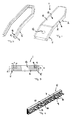
- eine perspektivische Gesamtansicht eines Aufbereiterzinkens nach einer vorteilhaften Ausführung der Erfindung,
- Fig. 2:
- eine Einzeldarstellung der Stahlkante in perspektivischer Ansicht ähnlich
Fig. 1 ohne den Kunststoffkern der Zinke, wobei der stegförmige, in den Kunststoff eingebettete Verankerungsabschnitt der Stahlkante zu sehen ist, - Fig. 3:
- eine Querschnittsansicht durch die Aufbereiterzinke aus
Fig. 1 , - Fig. 4:
- eine ausschnittsweise, perspektivische Ansicht der Stahlkante und deren stegförmigen Verankerungsabschnitts, die eine Formprofilierung des stegförmigen Verankerungsabschnitts in Form von Ausstanzungen und zungenförmigen Stanzvorsprüngen zeigt, und
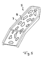
- Fig. 5:
- eine perspektivische Einzeldarstellung einer Stahlkante nach einer weiteren Ausführung der Erfindung, gemäß der ein durchgehender, plattenförmiger Verankerungsabschnitt mit Ausstanzungen vorgesehen ist.
- Wie
Fig. 1 zeigt, kann die Zinke 1 einen im Wesentlichen plattenförmigen Arbeitsschenkel 2 umfassen, an den ein Befestigungsschenkel 11 mit einem Montage- bzw. Befestigungsloch 12 anschließt, wobei der ebenfalls plattenförmige Befestigungsschenkel 11 gegenüber dem Arbeitsschenkel 2 leicht abgeknickt angeordnet sein kann, um den Arbeitsschenkel 2 in der gewünschten Weise schräg anzustellen. Wie die Zeichnungen zeigen, kann zwischen Arbeitsschenkel 2 und Befestigungsschenkel 11 ein stumpfer Winkel von etwa 150-170° vorgesehen sein, wobei dies natürlich in Abhängigkeit der jeweils benötigten Zinke variieren kann. Beispielsweise könnten auch Zinken mit zwei Arbeitsschenkeln vorgesehen werden, die durch einen gemeinsamen Befestigungsschenkel miteinander verbunden sind, so dass insgesamt ein näherungsweise U-förmiger Zinkenkorpus entsteht. Besonders vorteilhaft ist die erfindungsgemäße Ausbildung jedoch bei Zinken mit einem Arbeitsschenkel 2 wie in den Zeichnungen gezeigt. - Der Arbeitsschenkel 2 besitzt Plattenform und eine - sehr grob gesprochen - rechteckige Kontur mit zwei zumindest näherungsweise parallel zueinander angeordneten längeren Kanten, die durch eine kürzere Endkante miteinander verbunden sind. Wie
Fig. 1 zeigt, besitzt dabei eine Kante des Arbeitsschenkels 2 zum freien Ende hin eine Abschrägung, so dass der Arbeitsschenkel insgesamt betrachtet nicht exakt rechteckig konturiert ist. - Der Kern 13 der Zinke 1 ist dabei aus Kunststoff spritzgegossen, wobei sich dieser Korpusabschnitt 6 aus Kunststoff über den Arbeitsschenkel 2 hinaus bis in den Befestigungsschenkel 11 hinein erstrecken kann, vgl.
Fig. 1 . Der den Kern 13 bildende Korpusabschnitt 6 aus Kunststoff ist dabei wiederum plattenförmig ausgebildet und entspricht im Wesentlichen der Konturierung des Arbeitsschenkels 2. Der genannte Kern 13 des Arbeitsschenkels 2 ist dabei von einer Stahlkante 5 eingefasst, die, wie in den Figuren gezeigt, einstückig um die gesamte Zinke 1 herum verlaufen kann und die Zinke 1 an drei Seiten einfasst, nämlich deren Vorderkante und deren Hinterkante sowie dem freien Endabschnitt. Lediglich im Bereich des Befestigungsschenkels 11 ist das dort vorgesehene Zinkenende nicht eingefasst, vgl.Fig. 1 . - Die aus dem Kunststoffkern 13 und der Stahlkante 5 bestehende Zinke 1 wird zum allergrößten Teil von dem genannten Kunststoffkern 13 gebildet. Volumenmäßig betrachtet macht die Stahlkante 5 weniger als 10 % des Zinkenkorpus aus.
- Die Stahlkante 5 umfasst dabei, wie dies
Fig. 3 zeigt, einen freiliegenden Kopfabschnitt 7, an den zum Kern 13 hin ein dünner Verankerungsabschnitt 8 in Form eines Stegs 9 anschließt, der in den Kunststoff-Korpusabschnitt 6 eingebettet ist. Der genannte Steg 9 ist hierbei vorteilhafterweise über den Querschnitt betrachtet in einem mittleren Abschnitt des verdickten Kopfabschnitts 7 angeordnet, so dass die Stahlkante 5 insgesamt betrachtet einen T-förmigen Querschnitt besitzt, vgl.Fig. 3 . Die Stahlkante 5, genauer gesagt deren Kopfabschnitt 7 besitzt vorteilhafterweise eine Dicke D, die im Wesentlichen der Dicke des plattenförmigen Arbeitsschenkels 2 entspricht. Die Stahlkante 5 deckt damit die gesamte Arbeitskante 4 der Zinke 1 ab und schützt den dahinter liegenden Kunststoff-Korpusabschnitt 6. - Die Dicke d des Verankerungsabschnitts 8 ist hingegen sehr viel kleiner als die Dicke des Arbeitsschenkels 2. Wie
Fig. 3 zeigt, kann sie nur etwa 1/6 bis 1/10 der Dicke des Arbeitsschenkels 2 und/oder des Kunststoff-Korpusabschnitts 6 betragen. Die Tiefe t des Verankerungsabschnitts 8, mit der der genannte Verankerungsabschnitt 8 sich in den Kunststoff-Korpusabschnitt 6 hinein erstreckt, kann variieren und je nach verwendetem Material des Kunststoff-Korpusabschnitts 6 zwischen 2 und 10 mm, insbesondere etwa 3-5 mm betragen. - Wie
Fig. 4 zeigt, ist der genannte stegförmige Verankerungsabschnitt 8 der Stahlkante 5 vorteilhafterweise mit einer Formschlussprofilierung 10 versehen, die gemäß gezeichneter Ausführung mehrere durchgangslochförmige Ausstanzungen 14 sowie Vorsprünge 15 umfasst, die in der gezeichneten Ausführung in Form von Ausstanz-Zungen ausgebildet sind. Die genannten Ausstanzungen 14 können zur innen liegenden Kante des Stegs 9 hin offen ausgebildet sein, wodurch das Einfließen des Spritzgussmaterials vereinfacht wird, vgl.Fig. 4 . In vorteilhafterweise Weiterbildung der Erfindung kann das Verhältnis von Durchbrüchen bzw. Ausstanzungen und Nicht-Ausstanzungen, d.h. das Verhältnis von Stegfläche zu nicht vorhandener Stegfläche im Bereich von 2:1 bis 1:2, insbesondere etwa 1:1 betragen, d.h. etwa 50 % der Stegfläche können ausgestanzt sein. Hierdurch wird ein hoher Formschluss bei ausreichender Festigkeit des Stegs erzielt. - Wie
Fig. 5 zeigt, kann der Steg 9 auch durchgehend in Form einer Platte ausgebildet sein, die die Kopfabschnitte 7 der Schenkel der umlaufenden Stahlkante miteinander verbindet. Der Kopfabschnitt 7 bildet sozusagen einen verdickten Randabschnitt der Platte, die nach Art einer Armierungsplatte in den Kunststoffkorpus sandwichartig eingearbeitet ist und sich durch den gesamten Arbeitsschenkel 2 hindurch erstreckt. WieFig. 5 zeigt, ist der durchgehende Steg 9 vorteilhafterweise mit Ausstanzungen versehen, durch die hindurch der Kunststoff strömen kann, so dass sich die beidseitig angeordneten Kunststoff-Korpusabschnitte 6 miteinander verbinden.
Claims (14)
- Zinke zur Erntegut- und/oder Bodenbearbeitung, mit zumindest einem Arbeitsschenkel (2) mit zumindest einer Arbeitskante (4), wobei der Arbeitsschenkel (2) als Kompositkorpus aus verschiedenen Materialien ausgebildet ist, wobei die Arbeitskante (4) zumindest teilweise von einer Stahlkante (5) gebildet ist, die an einem Korpusabschnitt (6) aus Nichtmetall verankert ist, dadurch gekennzeichnet, dass der Korpusabschnitt (6) aus Nichtmetall einen Kernbereich des Arbeitsschenkels (2) bildet, welcher Kernbereich von der Stahlkante (5) eingefasst ist, wobei der nichtmetallische Korpusabschnitt (6) in Richtung der Arbeitsbewegung der Zinke betrachtet innerhalb der Abdeckung und/oder Breite des Kopfabschnitts (7) der Stahlkante (5) liegt.
- Zinke nach dem vorhergehenden Anspruch, wobei die Stahlkante (5) durchgängig um mehrere Seiten des Arbeitsschenkels (2) herum laufend ausgebildet ist und/oder den Arbeitsschenkel (2) mehrseitig nach Art eines mehrschenkligen Rahmens einfasst.
- Zinke nach einem der vorhergehenden Ansprüche, wobei die Stahlkante (5) einen zumindest teilweise freiliegenden Kopfabschnitt (7) sowie einen mit dem Kopfabschnitt (7) verbundenen Verankerungsabschnitt (8), der zumindest teilweise von dem nichtmetallischen Korpusabschnitt (6) bedeckt, insbesondere vollständig in den genannten Korpusabschnitt (6) eingebettet ist, aufweist, wobei der Kopfabschnitt (7) einen im Querschnitt verdickten Stahlkantenabschnitt bildet, an den ein Steg (9), der den Verankerungsabschnitt (8) bildet, anschließt, wobei vorzugsweise der Kopfabschnitt (7) eine Dicke (D) besitzt, die deutlich größer als die Dicke (d) des Stegs (9) ist und/oder im Wesentlichen der Dicke des Arbeitsschenkels (2) entspricht.
- Zinke nach dem vorhergehenden Anspruch, wobei der Verankerungsabschnitt (8) der Stahlkante (5) eine zumindest abschnittsweise uneben geformte Oberfläche mit einer Formschlussprofilierung (10) zur Erzielung eines Formschlusses zwischen dem Verankerungsabschnitt (8) und dem nichtmetallischen Korpusabschnitt (6), insbesondere in Form von Ausnehmungen und/oder Vorsprüngen und/oder Hinterschneidungen, aufweist.
- Zinke nach dem vorhergehenden Anspruch, wobei der Verankerungsabschnitt (8) einen Steg (9) bildet, der zumindest eine Ausstanzung und/oder zumindest eine Falzung und/oder zumindest eine Wellung und/oder zumindest eine Delle und/oder zumindest eines Riffelung und/oder zumindest einen Haken zur Verankerung in dem nichtmetallischen Korpusabschnitt (6) aufweist, wobei vorzugsweise die Stahlkante (5) als Stanzbiegeteil ausgebildet ist.
- Zinke nach einem der vorhergehenden Ansprüche, wobei die Stahlkante (5) vom Rand einer Armierungsplatte gebildet ist, die sich durch den Arbeitsschenkel (2) hindurch bis zu dessen gegenüberliegenden Rändern hin erstreckt, wobei die Armierungsplatte sandwichartig zwischen zwei nichtmetallischen, im Wesentlichen plattenförmigen Korpusteilen angeordnet ist oder zwei voneinander beabstandete Armierungsplatten zwischen sich sandwichartig den nichtmetallischen, etwa plattenförmigen Korpusteil (6) aufnehmen.
- Zinke nach einem der vorhergehenden Ansprüche, wobei der nichtmetallische Korpusteil (6) aus Kunststoff besteht, vorzugsweise spritzgegossen, insbesondere an die Stahlkante (5) angespritzt ist.
- Zinke nach einem der vorhergehenden Ansprüche, wobei der nichtmetallische Korpusteil (6) aus einem thermoplastischen Kunststoff, insbesondere Polyurethan oder Polyamid, besteht.
- Zinke nach einem der vorhergehenden Ansprüche, wobei der Kompositkorpus zum größeren Teil aus Kunststoff und zum kleineren Teil aus Stahl besteht, wobei die Stahlkante (5) volumenmäßig weniger als 50 %, vorzugsweise weniger als 25 %, insbesondere weniger als 10 % des Arbeitsschenkels (2) ausmacht.
- Zinke nach Anspruch 3 oder einem der auf Anspruch 3 rückbezogenen Ansprüche, wobei der Verankerungsabschnitt (8) der Stahlkante (5) eine Dicke von weniger als 33 %, vorzugsweise weniger als 25 %, insbesondere zwischen 5 und 10 % der Dicke des nichtmetallischen Korpusabschnitts (6) besitzt.
- Zinke nach Anspruch 3 oder einem der auf Anspruch 3 rückbezogenen Ansprüche, wobei der freiliegende Kopfabschnitt (7) der Stahlkante (5) in Arbeitsrichtung der Zinke (1) betrachtet eine Tiefe von weniger als 20 %, vorzugsweise weniger als 10 %, insbesondere etwa zwischen 5 % und 10 %, der Tiefe des Arbeitsschenkels (2) der Zinke (1) besitzt.
- Zinke nach einem der vorhergehenden Ansprüche, wobei die Stahlkante (5) zumindest abschnittsweise einen geraden Verlauf und abschnittsweise einen gekrümmten oder geknickten Verlauf besitzt.
- Arbeitsrotor einer Erntegut- und/oder Bodenbearbeitungsmaschine, mit einer Drehachse, um die der Arbeitsrotor drehbar gelagert und/oder rotatorisch antreibbar ist, sowie mit zumindest einer von der Drehachse beabstandet angeordneten Zinke (1) gemäß einem der vorhergehenden Ansprüche.
- Erntegutaufbereiter mit einer Zinke (1) nach einem der Ansprüche 1-12.
Priority Applications (1)
| Application Number | Priority Date | Filing Date | Title |
|---|---|---|---|
| PL12007020T PL2583542T3 (pl) | 2011-10-17 | 2012-10-10 | Palec roboczy |
Applications Claiming Priority (1)
| Application Number | Priority Date | Filing Date | Title |
|---|---|---|---|
| DE102011116257A DE102011116257A1 (de) | 2011-10-17 | 2011-10-17 | Aufbereiterzinke |
Publications (2)
| Publication Number | Publication Date |
|---|---|
| EP2583542A1 EP2583542A1 (de) | 2013-04-24 |
| EP2583542B1 true EP2583542B1 (de) | 2015-01-14 |
Family
ID=47142864
Family Applications (1)
| Application Number | Title | Priority Date | Filing Date |
|---|---|---|---|
| EP12007020.6A Not-in-force EP2583542B1 (de) | 2011-10-17 | 2012-10-10 | Aufbereiterzinke |
Country Status (4)
| Country | Link |
|---|---|
| EP (1) | EP2583542B1 (de) |
| DE (1) | DE102011116257A1 (de) |
| DK (1) | DK2583542T3 (de) |
| PL (1) | PL2583542T3 (de) |
Families Citing this family (2)
| Publication number | Priority date | Publication date | Assignee | Title |
|---|---|---|---|---|
| CN103736976B (zh) * | 2013-11-15 | 2015-10-14 | 东南大学 | 一种松土机上的合金松土齿及其制造方法 |
| DE202015000720U1 (de) * | 2015-01-29 | 2016-05-02 | Alois Pöttinger Maschinenfabrik Ges.m.b.H. | Säschartragarm |
Family Cites Families (6)
| Publication number | Priority date | Publication date | Assignee | Title |
|---|---|---|---|---|
| GB2117214B (en) * | 1982-03-26 | 1986-05-21 | Nat Res Dev | Crop engaging device and method |
| NL8400869A (nl) * | 1984-03-19 | 1985-10-16 | Texas Industries Inc | Machine met ten minste een aangedreven harkorgaan. |
| GB8709200D0 (en) * | 1987-04-16 | 1987-05-20 | Klinner W E | Crop engaging device |
| EP0972436B1 (de) | 1998-07-17 | 2005-01-05 | Kobashi Kogyo Co., Ltd. | Bodenbearbeitungszinken |
| EP1346621A1 (de) | 2002-03-22 | 2003-09-24 | Rabe Agrarsysteme GmbH & Co. KG | Zinken für ein Bodenbearbeitungsgerät |
| EP1704768A1 (de) | 2005-03-26 | 2006-09-27 | Deere & Company | Zinke eines Aufbereiterrotors |
-
2011
- 2011-10-17 DE DE102011116257A patent/DE102011116257A1/de not_active Withdrawn
-
2012
- 2012-10-10 DK DK12007020.6T patent/DK2583542T3/en active
- 2012-10-10 PL PL12007020T patent/PL2583542T3/pl unknown
- 2012-10-10 EP EP12007020.6A patent/EP2583542B1/de not_active Not-in-force
Also Published As
| Publication number | Publication date |
|---|---|
| EP2583542A1 (de) | 2013-04-24 |
| DK2583542T3 (en) | 2015-02-23 |
| PL2583542T3 (pl) | 2015-06-30 |
| DE102011116257A1 (de) | 2013-04-18 |
Similar Documents
| Publication | Publication Date | Title |
|---|---|---|
| EP2238021B1 (de) | Verbindungsanordnung zum verbinden zweier versteifungselemente unterschiedlichen querschnittprofils für ein luft- oder raumfahrzeug, und ein schalenbauteil | |
| WO2008015233A1 (de) | 'ventilatorschaufel | |
| WO2012065593A1 (de) | Schloss mit modifizierter federlippe für kraftfahrzeugtüren | |
| EP3560310A1 (de) | Schneidelement für eine landwirtschaftliche maschine | |
| EP2583542B1 (de) | Aufbereiterzinke | |
| DE102010052816A1 (de) | Erntevorsatz für eine Erntemaschine | |
| AT509579B1 (de) | Ährenheber für eine fahrbare erntemaschine | |
| AT510559B1 (de) | Langlaufschi mit wenigstens einem mittel zur rückgleithemmung | |
| EP1909930B1 (de) | Ski oder snowboard mit verbesserter torsionssteifigkeit | |
| DE202009008582U1 (de) | Bodenbearbeitungswerkzeug | |
| EP3103320B1 (de) | Tragschiene eines ährenhebers für erntegut | |
| DE212014000204U1 (de) | Ährenheber | |
| EP1839819B1 (de) | Armierungskörper eines Messergriffs zur Anbindung an eine Messerklinge und Verfahren zur Herstellung eines Messers | |
| DE102016112204B4 (de) | Werkzeug und Hartstoffelement für ein Werkzeug | |
| DE202017103891U1 (de) | Bodenbegrenzungsvorrichtung | |
| DE20115919U1 (de) | Schlagzinke eines Futteraufbereiters | |
| EP2080429B1 (de) | Schutzeinrichtung, insbesondere Zapfwellenschutz, für ein Endstück einer Welle | |
| DE202020104040U1 (de) | Bodenbearbeitungszinken | |
| DE60211249T2 (de) | Ski für Alpinskifahren | |
| EP2090804B1 (de) | Verbindung zweier Enden eines Fördergurts sowie Verwendung einer derartigen Verbindung | |
| DE102008059817A1 (de) | Holzträger für den Baubereich | |
| DE102005020464A1 (de) | Zinkenträgergehäuse, Zinkenträger und Aufnehmer für landwirtschaftliches Erntegut | |
| DE202023002908U1 (de) | Bodenbearbeitungswerkzeug und Satz von mindestens zwei Bodenbearbeitungswerkzeugen | |
| DE102023120501A1 (de) | Bodenbearbeitungswerkzeug und Verfahren zur Herstellung | |
| DE102023120500A1 (de) | Bodenbearbeitungswerkzeug und Verfahren zur Herstellung |
Legal Events
| Date | Code | Title | Description |
|---|---|---|---|
| PUAI | Public reference made under article 153(3) epc to a published international application that has entered the european phase |
Free format text: ORIGINAL CODE: 0009012 |
|
| AK | Designated contracting states |
Kind code of ref document: A1 Designated state(s): AL AT BE BG CH CY CZ DE DK EE ES FI FR GB GR HR HU IE IS IT LI LT LU LV MC MK MT NL NO PL PT RO RS SE SI SK SM TR |
|
| AX | Request for extension of the european patent |
Extension state: BA ME |
|
| 17P | Request for examination filed |
Effective date: 20131024 |
|
| RIC1 | Information provided on ipc code assigned before grant |
Ipc: A01D 43/10 20060101ALI20140630BHEP Ipc: A01D 82/00 20060101ALI20140630BHEP Ipc: A01B 33/10 20060101AFI20140630BHEP |
|
| GRAP | Despatch of communication of intention to grant a patent |
Free format text: ORIGINAL CODE: EPIDOSNIGR1 |
|
| INTG | Intention to grant announced |
Effective date: 20140923 |
|
| RIN1 | Information on inventor provided before grant (corrected) |
Inventor name: POETTINGER, KLAUS Inventor name: LEHNER, JOSEF Inventor name: BALDINGER, MARKUS |
|
| GRAS | Grant fee paid |
Free format text: ORIGINAL CODE: EPIDOSNIGR3 |
|
| GRAA | (expected) grant |
Free format text: ORIGINAL CODE: 0009210 |
|
| AK | Designated contracting states |
Kind code of ref document: B1 Designated state(s): AL AT BE BG CH CY CZ DE DK EE ES FI FR GB GR HR HU IE IS IT LI LT LU LV MC MK MT NL NO PL PT RO RS SE SI SK SM TR |
|
| REG | Reference to a national code |
Ref country code: GB Ref legal event code: FG4D Free format text: NOT ENGLISH |
|
| REG | Reference to a national code |
Ref country code: CH Ref legal event code: EP |
|
| REG | Reference to a national code |
Ref country code: IE Ref legal event code: FG4D Free format text: LANGUAGE OF EP DOCUMENT: GERMAN |
|
| REG | Reference to a national code |
Ref country code: AT Ref legal event code: REF Ref document number: 706501 Country of ref document: AT Kind code of ref document: T Effective date: 20150215 |
|
| REG | Reference to a national code |
Ref country code: DK Ref legal event code: T3 Effective date: 20150219 |
|
| REG | Reference to a national code |
Ref country code: DE Ref legal event code: R096 Ref document number: 502012002070 Country of ref document: DE Effective date: 20150305 |
|
| REG | Reference to a national code |
Ref country code: NL Ref legal event code: T3 |
|
| REG | Reference to a national code |
Ref country code: LT Ref legal event code: MG4D |
|
| REG | Reference to a national code |
Ref country code: PL Ref legal event code: T3 |
|
| PG25 | Lapsed in a contracting state [announced via postgrant information from national office to epo] |
Ref country code: BG Free format text: LAPSE BECAUSE OF FAILURE TO SUBMIT A TRANSLATION OF THE DESCRIPTION OR TO PAY THE FEE WITHIN THE PRESCRIBED TIME-LIMIT Effective date: 20150414 Ref country code: HR Free format text: LAPSE BECAUSE OF FAILURE TO SUBMIT A TRANSLATION OF THE DESCRIPTION OR TO PAY THE FEE WITHIN THE PRESCRIBED TIME-LIMIT Effective date: 20150114 Ref country code: NO Free format text: LAPSE BECAUSE OF FAILURE TO SUBMIT A TRANSLATION OF THE DESCRIPTION OR TO PAY THE FEE WITHIN THE PRESCRIBED TIME-LIMIT Effective date: 20150414 Ref country code: LT Free format text: LAPSE BECAUSE OF FAILURE TO SUBMIT A TRANSLATION OF THE DESCRIPTION OR TO PAY THE FEE WITHIN THE PRESCRIBED TIME-LIMIT Effective date: 20150114 Ref country code: ES Free format text: LAPSE BECAUSE OF FAILURE TO SUBMIT A TRANSLATION OF THE DESCRIPTION OR TO PAY THE FEE WITHIN THE PRESCRIBED TIME-LIMIT Effective date: 20150114 Ref country code: SE Free format text: LAPSE BECAUSE OF FAILURE TO SUBMIT A TRANSLATION OF THE DESCRIPTION OR TO PAY THE FEE WITHIN THE PRESCRIBED TIME-LIMIT Effective date: 20150114 |
|
| PG25 | Lapsed in a contracting state [announced via postgrant information from national office to epo] |
Ref country code: GR Free format text: LAPSE BECAUSE OF FAILURE TO SUBMIT A TRANSLATION OF THE DESCRIPTION OR TO PAY THE FEE WITHIN THE PRESCRIBED TIME-LIMIT Effective date: 20150415 Ref country code: RS Free format text: LAPSE BECAUSE OF FAILURE TO SUBMIT A TRANSLATION OF THE DESCRIPTION OR TO PAY THE FEE WITHIN THE PRESCRIBED TIME-LIMIT Effective date: 20150114 Ref country code: IS Free format text: LAPSE BECAUSE OF FAILURE TO SUBMIT A TRANSLATION OF THE DESCRIPTION OR TO PAY THE FEE WITHIN THE PRESCRIBED TIME-LIMIT Effective date: 20150514 Ref country code: LV Free format text: LAPSE BECAUSE OF FAILURE TO SUBMIT A TRANSLATION OF THE DESCRIPTION OR TO PAY THE FEE WITHIN THE PRESCRIBED TIME-LIMIT Effective date: 20150114 |
|
| REG | Reference to a national code |
Ref country code: DE Ref legal event code: R097 Ref document number: 502012002070 Country of ref document: DE |
|
| REG | Reference to a national code |
Ref country code: FR Ref legal event code: PLFP Year of fee payment: 4 |
|
| PG25 | Lapsed in a contracting state [announced via postgrant information from national office to epo] |
Ref country code: RO Free format text: LAPSE BECAUSE OF FAILURE TO SUBMIT A TRANSLATION OF THE DESCRIPTION OR TO PAY THE FEE WITHIN THE PRESCRIBED TIME-LIMIT Effective date: 20150114 Ref country code: EE Free format text: LAPSE BECAUSE OF FAILURE TO SUBMIT A TRANSLATION OF THE DESCRIPTION OR TO PAY THE FEE WITHIN THE PRESCRIBED TIME-LIMIT Effective date: 20150114 Ref country code: CZ Free format text: LAPSE BECAUSE OF FAILURE TO SUBMIT A TRANSLATION OF THE DESCRIPTION OR TO PAY THE FEE WITHIN THE PRESCRIBED TIME-LIMIT Effective date: 20150114 Ref country code: SK Free format text: LAPSE BECAUSE OF FAILURE TO SUBMIT A TRANSLATION OF THE DESCRIPTION OR TO PAY THE FEE WITHIN THE PRESCRIBED TIME-LIMIT Effective date: 20150114 |
|
| PLBE | No opposition filed within time limit |
Free format text: ORIGINAL CODE: 0009261 |
|
| STAA | Information on the status of an ep patent application or granted ep patent |
Free format text: STATUS: NO OPPOSITION FILED WITHIN TIME LIMIT |
|
| 26N | No opposition filed |
Effective date: 20151015 |
|
| PG25 | Lapsed in a contracting state [announced via postgrant information from national office to epo] |
Ref country code: SI Free format text: LAPSE BECAUSE OF FAILURE TO SUBMIT A TRANSLATION OF THE DESCRIPTION OR TO PAY THE FEE WITHIN THE PRESCRIBED TIME-LIMIT Effective date: 20150114 |
|
| REG | Reference to a national code |
Ref country code: DE Ref legal event code: R119 Ref document number: 502012002070 Country of ref document: DE |
|
| PG25 | Lapsed in a contracting state [announced via postgrant information from national office to epo] |
Ref country code: LU Free format text: LAPSE BECAUSE OF FAILURE TO SUBMIT A TRANSLATION OF THE DESCRIPTION OR TO PAY THE FEE WITHIN THE PRESCRIBED TIME-LIMIT Effective date: 20151010 |
|
| REG | Reference to a national code |
Ref country code: CH Ref legal event code: PL |
|
| PG25 | Lapsed in a contracting state [announced via postgrant information from national office to epo] |
Ref country code: MC Free format text: LAPSE BECAUSE OF FAILURE TO SUBMIT A TRANSLATION OF THE DESCRIPTION OR TO PAY THE FEE WITHIN THE PRESCRIBED TIME-LIMIT Effective date: 20150114 |
|
| PG25 | Lapsed in a contracting state [announced via postgrant information from national office to epo] |
Ref country code: DE Free format text: LAPSE BECAUSE OF NON-PAYMENT OF DUE FEES Effective date: 20160503 Ref country code: LI Free format text: LAPSE BECAUSE OF NON-PAYMENT OF DUE FEES Effective date: 20151031 Ref country code: CH Free format text: LAPSE BECAUSE OF NON-PAYMENT OF DUE FEES Effective date: 20151031 |
|
| REG | Reference to a national code |
Ref country code: FR Ref legal event code: PLFP Year of fee payment: 5 |
|
| PG25 | Lapsed in a contracting state [announced via postgrant information from national office to epo] |
Ref country code: HU Free format text: LAPSE BECAUSE OF FAILURE TO SUBMIT A TRANSLATION OF THE DESCRIPTION OR TO PAY THE FEE WITHIN THE PRESCRIBED TIME-LIMIT; INVALID AB INITIO Effective date: 20121010 Ref country code: SM Free format text: LAPSE BECAUSE OF FAILURE TO SUBMIT A TRANSLATION OF THE DESCRIPTION OR TO PAY THE FEE WITHIN THE PRESCRIBED TIME-LIMIT Effective date: 20150114 |
|
| GBPC | Gb: european patent ceased through non-payment of renewal fee |
Effective date: 20161010 |
|
| PG25 | Lapsed in a contracting state [announced via postgrant information from national office to epo] |
Ref country code: CY Free format text: LAPSE BECAUSE OF FAILURE TO SUBMIT A TRANSLATION OF THE DESCRIPTION OR TO PAY THE FEE WITHIN THE PRESCRIBED TIME-LIMIT Effective date: 20150114 |
|
| PG25 | Lapsed in a contracting state [announced via postgrant information from national office to epo] |
Ref country code: BE Free format text: LAPSE BECAUSE OF NON-PAYMENT OF DUE FEES Effective date: 20151031 Ref country code: GB Free format text: LAPSE BECAUSE OF NON-PAYMENT OF DUE FEES Effective date: 20161010 |
|
| PG25 | Lapsed in a contracting state [announced via postgrant information from national office to epo] |
Ref country code: MT Free format text: LAPSE BECAUSE OF FAILURE TO SUBMIT A TRANSLATION OF THE DESCRIPTION OR TO PAY THE FEE WITHIN THE PRESCRIBED TIME-LIMIT Effective date: 20150114 |
|
| REG | Reference to a national code |
Ref country code: FR Ref legal event code: PLFP Year of fee payment: 6 |
|
| PGFP | Annual fee paid to national office [announced via postgrant information from national office to epo] |
Ref country code: IT Payment date: 20170925 Year of fee payment: 6 |
|
| PGFP | Annual fee paid to national office [announced via postgrant information from national office to epo] |
Ref country code: FI Payment date: 20171002 Year of fee payment: 6 Ref country code: FR Payment date: 20171012 Year of fee payment: 6 Ref country code: DK Payment date: 20171013 Year of fee payment: 6 |
|
| PGFP | Annual fee paid to national office [announced via postgrant information from national office to epo] |
Ref country code: PL Payment date: 20170927 Year of fee payment: 6 Ref country code: IE Payment date: 20171012 Year of fee payment: 6 Ref country code: NL Payment date: 20171013 Year of fee payment: 6 |
|
| PG25 | Lapsed in a contracting state [announced via postgrant information from national office to epo] |
Ref country code: PT Free format text: LAPSE BECAUSE OF FAILURE TO SUBMIT A TRANSLATION OF THE DESCRIPTION OR TO PAY THE FEE WITHIN THE PRESCRIBED TIME-LIMIT Effective date: 20150114 Ref country code: TR Free format text: LAPSE BECAUSE OF FAILURE TO SUBMIT A TRANSLATION OF THE DESCRIPTION OR TO PAY THE FEE WITHIN THE PRESCRIBED TIME-LIMIT Effective date: 20150114 Ref country code: MK Free format text: LAPSE BECAUSE OF FAILURE TO SUBMIT A TRANSLATION OF THE DESCRIPTION OR TO PAY THE FEE WITHIN THE PRESCRIBED TIME-LIMIT Effective date: 20150114 |
|
| PG25 | Lapsed in a contracting state [announced via postgrant information from national office to epo] |
Ref country code: AL Free format text: LAPSE BECAUSE OF FAILURE TO SUBMIT A TRANSLATION OF THE DESCRIPTION OR TO PAY THE FEE WITHIN THE PRESCRIBED TIME-LIMIT Effective date: 20150114 |
|
| REG | Reference to a national code |
Ref country code: AT Ref legal event code: MM01 Ref document number: 706501 Country of ref document: AT Kind code of ref document: T Effective date: 20171010 |
|
| PG25 | Lapsed in a contracting state [announced via postgrant information from national office to epo] |
Ref country code: AT Free format text: LAPSE BECAUSE OF NON-PAYMENT OF DUE FEES Effective date: 20171010 |
|
| REG | Reference to a national code |
Ref country code: DK Ref legal event code: EBP Effective date: 20181031 |
|
| REG | Reference to a national code |
Ref country code: NL Ref legal event code: MM Effective date: 20181101 |
|
| REG | Reference to a national code |
Ref country code: IE Ref legal event code: MM4A |
|
| PG25 | Lapsed in a contracting state [announced via postgrant information from national office to epo] |
Ref country code: FI Free format text: LAPSE BECAUSE OF NON-PAYMENT OF DUE FEES Effective date: 20181010 Ref country code: NL Free format text: LAPSE BECAUSE OF NON-PAYMENT OF DUE FEES Effective date: 20181101 |
|
| PG25 | Lapsed in a contracting state [announced via postgrant information from national office to epo] |
Ref country code: FR Free format text: LAPSE BECAUSE OF NON-PAYMENT OF DUE FEES Effective date: 20181031 |
|
| PG25 | Lapsed in a contracting state [announced via postgrant information from national office to epo] |
Ref country code: DK Free format text: LAPSE BECAUSE OF NON-PAYMENT OF DUE FEES Effective date: 20181031 Ref country code: IE Free format text: LAPSE BECAUSE OF NON-PAYMENT OF DUE FEES Effective date: 20181010 Ref country code: IT Free format text: LAPSE BECAUSE OF NON-PAYMENT OF DUE FEES Effective date: 20181010 |
|
| PG25 | Lapsed in a contracting state [announced via postgrant information from national office to epo] |
Ref country code: PL Free format text: LAPSE BECAUSE OF NON-PAYMENT OF DUE FEES Effective date: 20181010 |