EP2583584B1 - Racleur multiple - Google Patents
Racleur multiple Download PDFInfo
- Publication number
- EP2583584B1 EP2583584B1 EP12007237.6A EP12007237A EP2583584B1 EP 2583584 B1 EP2583584 B1 EP 2583584B1 EP 12007237 A EP12007237 A EP 12007237A EP 2583584 B1 EP2583584 B1 EP 2583584B1
- Authority
- EP
- European Patent Office
- Prior art keywords
- stripper
- stripping
- stripping member
- cosmetics
- reservoir
- Prior art date
- Legal status (The legal status is an assumption and is not a legal conclusion. Google has not performed a legal analysis and makes no representation as to the accuracy of the status listed.)
- Not-in-force
Links
- 239000002537 cosmetic Substances 0.000 claims description 69
- 238000005452 bending Methods 0.000 claims description 11
- 230000007423 decrease Effects 0.000 claims description 3
- 230000002093 peripheral effect Effects 0.000 claims description 2
- 230000000694 effects Effects 0.000 description 7
- 238000000605 extraction Methods 0.000 description 3
- 230000001154 acute effect Effects 0.000 description 2
- 230000018109 developmental process Effects 0.000 description 2
- 238000005507 spraying Methods 0.000 description 2
- 238000004891 communication Methods 0.000 description 1
- 150000001875 compounds Chemical class 0.000 description 1
- 230000003247 decreasing effect Effects 0.000 description 1
- 230000008021 deposition Effects 0.000 description 1
- 230000012447 hatching Effects 0.000 description 1
- 210000000056 organ Anatomy 0.000 description 1
- 230000000007 visual effect Effects 0.000 description 1
Images

Classifications
-
- A—HUMAN NECESSITIES
- A45—HAND OR TRAVELLING ARTICLES
- A45D—HAIRDRESSING OR SHAVING EQUIPMENT; EQUIPMENT FOR COSMETICS OR COSMETIC TREATMENTS, e.g. FOR MANICURING OR PEDICURING
- A45D34/00—Containers or accessories specially adapted for handling liquid toiletry or cosmetic substances, e.g. perfumes
- A45D34/04—Appliances specially adapted for applying liquid, e.g. using roller or ball
- A45D34/042—Appliances specially adapted for applying liquid, e.g. using roller or ball using a brush or the like
- A45D34/045—Appliances specially adapted for applying liquid, e.g. using roller or ball using a brush or the like connected to the cap of the container
- A45D34/046—Appliances specially adapted for applying liquid, e.g. using roller or ball using a brush or the like connected to the cap of the container comprising a wiper
-
- A—HUMAN NECESSITIES
- A45—HAND OR TRAVELLING ARTICLES
- A45D—HAIRDRESSING OR SHAVING EQUIPMENT; EQUIPMENT FOR COSMETICS OR COSMETIC TREATMENTS, e.g. FOR MANICURING OR PEDICURING
- A45D40/00—Casings or accessories specially adapted for storing or handling solid or pasty toiletry or cosmetic substances, e.g. shaving soaps or lipsticks
- A45D40/26—Appliances specially adapted for applying pasty paint, e.g. using roller, using a ball
- A45D40/262—Appliances specially adapted for applying pasty paint, e.g. using roller, using a ball using a brush or the like
- A45D40/265—Appliances specially adapted for applying pasty paint, e.g. using roller, using a ball using a brush or the like connected to the cap of the container
- A45D40/267—Appliances specially adapted for applying pasty paint, e.g. using roller, using a ball using a brush or the like connected to the cap of the container comprising a wiper
Definitions
- the invention relates to a scraper according to the preamble of claim 1.
- scrapers are in various forms in use to strip cosmetic applicators, which, as long as they are unused, dip into a cosmetic stock, from which they are pulled out to make the applicator ready for use.
- a recurring problem is caused by the fact that an applicator heavily loaded with cosmetic mass prevents air from flowing into the reservoir during extraction of the applicator from the cosmetic reservoir, since the cosmetic applicator and its charge seal almost airtight against the wiper lip.
- a negative pressure builds up in the cosmetic reservoir, which collapses abruptly as soon as the distal, ie the handle remote from the end of the applicator has passed the wiper lip.
- the sudden collapse of the negative pressure leads to a loud noise that can be described as a "pop". This noise is often perceived as a contradiction to a high-quality visual and haptic presentation of the cosmetic unit.
- the US 5,349,972 discloses an applicator having a housing containing a primary and a secondary wiper. Under the secondary scraper, there is mounted a cylindrical device having local slits.
- the WO 2010/131215 A2 describes a scraper in which the wiper members are attached to each other, side vents are not disclosed.
- the invention is based on the object to provide a scraper or provided with a scraper cosmetic unit, which permanently reduced tendency for noise and / or tendency to splash when Pulling out the applicator shows or frees the applicator at the distal end of excess cosmetic.
- a scraper for stripping a cosmetic applicator with a preferably tubular holding portion for setting the scraper to a cosmetic reservoir is proposed, the more in the direction of action - d. H. regularly in the removal direction of the cosmetic applicator - arranged in succession Abstreiforgane, of which at least one wiper member is held on the holding portion or the adjacent wiper member that it communicates both on its front and on its back unhindered with the cosmetic-storing space.
- Such unimpeded communication is in any case if, directly next to the wiper member, preferably by the shortest possible route, there is a direct connection between the front side of the wiper member (seen in the withdrawal direction) and the rear side of the wiper member.
- connection is so great that even in the course of the period of intended use of the cosmetic unit in question, no complete clogging of the compound is to be feared.
- a shortest possible connection is z. B. given when the wiper member in question is a disc-shaped body and immediately along the peripheral edge of the disc-shaped body, a connection between its front and back is created.
- scraper for stripping a cosmetic applicator with a preferably tubular holding portion Presetting the scraper on a cosmetic storage container.
- this scraper has a plurality of successively arranged in the direction of action Abstreiforgane, of which at least one wiper member is held only by means of several columns on the holding portion or the adjacent wiper member.
- At least one wiper member of the wiper is or are designed as a disk arranged substantially perpendicular to the wiper longitudinal axis L.
- a disk in this sense is considered to be a structure whose extent in the direction parallel to the longitudinal axis is not more than 5.5 times, better not more than 3 times, the maximum wall thickness in the direction parallel to the wall thickness.
- the canister-inward major surface of one or more of said disks is substantially conical.
- At least one wiper of the wiper preferably at least two wipers of the wiper have a number of slots which divide the respective wiper member into several segments, wherein the segments are preferably formed in the manner of cake pieces whose tips are in the middle of each other or meet and abut each other with their flanks or only separated by a small gap.
- a gap is then small in any case The meaning of this development, if its maximum width is not more than 1 mm and preferably not more than 0.5 mm.
- At least one wiper of the wiper better have at least two wiper of the scraper on a central opening, which is always unlocked, as long as no cosmetic applicator protrudes through the wiper member in question.
- the segments of the segmented wiper member are designed such that they form cantilevered bending beams that bend resiliently when pulling the cosmetic applicator in the direction of tensile force, wherein the bending counteracting spring force is so great that the segments already then essentially in their snap back undeflected position when the cosmetic applicator in the course of its extraction has passed the wiper in question predominantly, but not yet completely.
- the holding portion forms a further wiper member.
- This is best done by forming a tubular body that tapers at its retainer inward end such that the taper forms a circular wiper lip, ideally completely circumferentially completely self-contained. With a such additional scraper can be ensured that the stem of the applicator is stripped optimally.
- stripping off of the stem takes place without an excessive stripping effect being exerted in the area of the bristle lining by this stripping member, for the proper stripping of which at least predominantly the other stripping organ is responsible.
- the tubular body is completely closed at its periphery, thereby forming a Abstreifervorhof, which communicates substantially and preferably exclusively on the scraper lip bordered by the scraper lip with the cosmetic-storing space.
- the scraper has a plurality of scraper elements arranged one behind the other in the direction of action, one of these scraper elements being arranged as wholly or substantially perpendicular to the scraper longitudinal axis, preferably slotted and ideally in accordance with one of the preceding claims Claims designed disk is formed and another of the Abstreiforgane is formed by a tubular body which tapers at its Beh Nativereinadedrtigen end such that the taper forms a circular, ideally in the circumferential direction completely self-contained wiper lip.
- slots are partially or preferably all not rectilinear, but preferably designed so that they form an S-shaped course.
- such a system is designed so that the said wiper member complies with at least 1 mm, more preferably 3 mm minimum distance to the or the walls of the Kosmetikvorrats constituers.
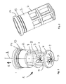
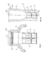
- FIG. 1 shows a side view of a first embodiment of the scraper according to the invention, installed in the neck of a bottle, which serves as a cosmetic reservoir.
- FIG. 2 shows a perspective side view of the first embodiment of the scraper according to the invention.
- FIG. 3 shows a perspective side view of the first embodiment of the scraper according to the invention in a section along the Abstreiferlticiansachse L.
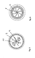
- FIG. 4 shows a plan view of the container einmaschinertige scraper of the scraper, which represents here the first embodiment.
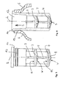
- FIG. 5 shows a side view of a second embodiment of the scraper according to the invention.
- FIG. 6 shows a perspective side view of the second embodiment of the scraper according to the invention.
- FIG. 7 shows a perspective side view of the second embodiment of the scraper according to the invention in a section along the Abstreiferlticiansachse L.
- FIG. 8 shows a plan view of the container inward wiper of the scraper, which is the second embodiment here.
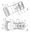
- FIGS. 9 to 12 show a third embodiment of the invention.
- the scraper 1 of the first embodiment consists of a holding section 2 and two Abstreiforganen 3 and 4.
- the holding section 2 is here, as it is preferred, formed as a circumferentially completely self-contained tubular body, by means of which the scraper 1 is fixed in the neck of the bottle 13, which serves as a cosmetic reservoir.
- the holding portion 2 is preferably provided with a collar-like stopper 14, which abuts against an end face of the bottle neck and thus limits the way by which the scraper 1 can be inserted into the bottle neck, and at the same time acts as a seal, so as to leak of the cosmetic to prevent from the container.
- the holding section 2 is additionally equipped with at least one locking member 15, which with a corresponding catch member or a corresponding surface of the bottle neck locked.
- the outer diameter of the holding portion 2 is usually adapted to the inner diameter of the neck provided for receiving his neck, so as to ensure a play-free fit of the scraper 1 in the radial direction.
- the holding portion 2 has a substantially constant inner diameter, that is, the holding portion 2 does not contribute as such to a substantial extent to the stripping effect.
- At its Be Scholeinericartigen end of the holding section 2 is in several columns 7 over. By means of these columns 7, a wiper member 3 is fixed to the holding portion 2.
- the wiper 3 is formed here as a disc, which is preferably circular.
- a disc in the sense of the invention is a structure having two major major surfaces and a comparatively small circumferential surface. The two major major surfaces are arranged so that they are substantially perpendicular to the AbstreiferlHarsachse L.
- this disc is slightly tapered, d. H. at least one of its two major major surfaces, but preferably both major major surfaces are not one hundred percent oriented perpendicular to AbstreiferlShsachse L, but instead instead preferably extend at an angle of 90 ° +/- max. 15 ° and ideally at an angle of 90 ° +/- max. 10 ° to the AbstreiferlHarsachse L.
- the two major major surfaces are tapered so that they are slightly inclined in the direction of the center of the disc in the direction in the direction in particular. This facilitates the reintroduction of the applicator.
- the disk is preferably between 0.5 and 1.75 mm thick in the direction parallel to the longitudinal axis, this area not being, despite the thickness of the disk decreasing towards the center fully exploited. It is provided with a number of slots extending from the center of the disc to the disc rim. In the case of the Fig. 1 to 4 In the preferred embodiment shown, two slots which are directly opposite one another in the center region always form an S-shaped slot arrangement, as a result of which, surprisingly, an improved wiping action is produced in comparison to exclusively straight slots.
- the straight or S-shaped slots divide most of the major major surfaces into cantilevered bending beams having a cake-pieced, triangular shape and like the pieces of a cake being arranged in a circle.
- each bending beam on its center-facing side is preferably in a range for which 42 ° ⁇ ⁇ ⁇ 28 °.
- Such designed tips "comb" the applicator very effectively and therefore cause especially bristled applicators a very good wiping result.
- the thickness of the disc decreases from its outer periphery toward the center of the disc, which positively influences the deformation behavior of the wiper member or its bending beam.
- the bending beams bend elastically when pulling out the cosmetics applicator.
- the bending force counteracting the bending spring is preferably so large that the segments already snap back into their undeflected position substantially when the cosmetic applicator has predominantly, but not yet completely, passed the relevant wiper member in the course of its extraction.
- the applicator handle remote from the free end of the applicator is very effectively stripped off.
- the slots terminate on the outside at an imaginary circle having a radius which is about% of the maximum disk radius so that the disc still has the required inherent stability despite the slits and does not permanently "invert" as the applicator is pulled through it.
- the disc is punched in its center.
- the hole diameter, which has the container interior facing disc preferably larger (ideally by at least 20%, better by at least 30%) than the hole diameter, which has the container opening facing disc, which will come soon to speak.
- the wiper 3 is held by means of several columns 7 on the holding portion 2 in position.
- These columns 7 are each preferably rectangular bars, ie structures whose length is substantially greater parallel to the longitudinal axis L of the scraper 1 than their width in the circumferential direction.
- the bars are each so slender that their extent RE in the circumferential direction is at most 7.5% and preferably at most 5% of the circumference along which the bars are set up.
- the bars can be wider and each make up a maximum of 10% of the circumference, but such an embodiment is not preferred, but in fact only the exception for which only secondary protection is claimed.
- the number of a wiper 3 holding rods is limited, so that a maximum of 4 such rods are provided for a wiper member 3.
- each rod should normally have an extension RE, which makes up a maximum of 5% of the circumference and better makes up a maximum of 3% of the circumference.
- the columns are evenly distributed along the circumference.
- the columns are preferably designed so that they have a thickness in the radial direction, which is greater than the measured in the radial direction wall thickness of the holding section 2.
- Die Fig. 4 illustrates this quite well, because it shows that the columns protrude in this embodiment, the inside over the inner surface of the holding portion 2.
- the wiper 4 is formed as a disc, as described above for the wiper member 3.
- the wiper 4 is also held by means of several columns on the preceding wiper member 3. Because of this, the wiper 4 can communicate freely with the space of the reservoir storing the cosmetic.
- the preferably only difference to the wiper 3 is that the hole diameter, which has the central hole of this disk-shaped wiper, is smaller than that of the disk-shaped wiper 3. Not least because of this, the wiper 4 is still a certain proportion of the cosmetic mass of the applicator strip, which had first passed the wiper 3, without being stripped.
- FIGS. 5 to 8 show a second embodiment of the invention.
- This second embodiment of the invention is designed substantially the same as the first embodiment of the invention. Because of this, what has been said for the first exemplary embodiment of the invention applies in the same way, unless otherwise stated in the differences described below.
- disc-shaped wiper members are completely flat in this embodiment, d. H. they are not conical, but their two major major surfaces are each oriented orthogonal to the longitudinal axis L.
- the holding portion 2 is shaped to taper toward the container inner side and form a circumferentially self-contained circular wiper lip.
- the holding portion 2 is formed conically at its container inside end. It is preferable that this circular wiper lip at the inner end of the conical section has the particular purpose of wiping off the handle of the applicator and freeing as much of the cosmetic adhering there as possible. Accordingly, this wiper lip is dimensioned.
- the circular applicator or the holding section 2 preferably has no bypass opening, d. H. no path bypassing the wiper lip to supply air to the cosmetic reservoir.
- this circular wiper lip is instead dimensioned such that it has a larger clear diameter than comparable wiper lips, which not only have the task of wiping off the applicator handle, but also the actual applicator body or the bristle cover of the applicator.
- the size of the clear diameter is selected according to the invention so that the circular wiper lip strikes substantially only the applicator stem and unfolds no significant wiping action relative to the actual applicator body or the bristle border of the applicator.
- the applicator handle is preferably dimensioned so that it still protrudes through the circular wiper lip when the applicator is pushed completely into its stowed position, as a result of which the cosmetic reservoir is completely sealed, so that the storing cosmetic can not pass the wiper even if the cosmetic wears Cosmetic unit is stored, for example, at higher temperatures in the head stand, which can occur involuntarily in a handbag.
- FIGS. 9 to 12 show a third embodiment of the invention.
- the embodiment is designed so that the two disc-shaped wiper members are designed to be 100% as in the first embodiment, while the associated holding portion forms an additional wiper member, as in the second embodiment.
- Scraper 1 for stripping a cosmetic applicator, wherein the scraper 1 has a plurality in the direction of action successively arranged scraper 3, 4, 5, one of these scraper as arranged substantially perpendicular to the AbstreiferlHarsachse L, preferably slotted and ideally equipped in accordance with the possibilities described in this application possibilities Disc is formed and another of the Abstreiforgane by a tubular body is formed, which tapers at its Be Scholeinissertigen end such that the taper forms a circular, ideally in the circumferential direction completely self-contained wiper lip 11.
- Scraper 1 for stripping a cosmetic applicator with a holding portion 2 for fixing the scraper 1 to a cosmetic reservoir 6, characterized in that the scraper 1 has a plurality of successively arranged Abstreiforgane 3, 4, 5, of which at least one wiper member only by means of several columns. 7 is held on the holding portion 2 or on the adjacent wiper member.
Landscapes
- Closures For Containers (AREA)
- Brushes (AREA)
- Containers And Packaging Bodies Having A Special Means To Remove Contents (AREA)
- Cosmetics (AREA)
Claims (14)
- Racleur (1) pour racler un applicateur de cosmétique comprenant une portion de maintien (2) pour immobiliser le racleur (1) sur un récipient de réserve de cosmétique (6) ; dans lequel le racleur (1) comprend plusieurs organes de raclage (3, 4, 5) agencés les uns derrière les autres en direction d'action et destinés à racler un applicateur de cosmétique, qui sont reliés à la portion de maintien et parmi lesquels au moins un organe de raclage est retenu sur la portion de maintien (2) ou sur l'organe de raclage voisin de telle manière qu'il communique sans entrave aussi bien sur son côté antérieur (V) que sur son côté postérieur (R) avec le volume (6) qui contient le cosmétique, caractérisé en ce qu'au moins un organe de raclage est retenu uniquement au moyen de plusieurs colonnettes (7), sous la configuration de barreaux, donc de structures dont l'extension en direction périphérique est respectivement au maximum 10 % de la périphérie, sur la portion de maintien (2) ou sur l'organe de raclage voisin.
- Racleur (1) selon la revendication 1 pour racler un applicateur de cosmétique comprenant une portion de maintien (2) pour immobiliser le racleur (1) sur un récipient de réserve de cosmétique (6) ; dans lequel le racleur (1) comprend plusieurs organes de raclage (3, 4, 5) agencés les uns derrière les autres en direction d'action, parmi lesquels au moins un organe de raclage est retenu sur la portion de maintien (2) ou sur l'organe de raclage voisin de telle manière qu'il communique sans entrave aussi bien sur son côté antérieur (V) que sur son côté postérieur (R) avec le volume (6) qui contient le cosmétique, caractérisé en ce que le racleur (1) comprend au moins deux organes de raclage (3, 4, 5) agencés l'un derrière les autres, qui sont retenus tous les deux sur la portion de maintien (2) ou sur l'organe de raclage voisin, de telle manière qu'ils communiquent sans entrave tous les deux aussi bien sur leur côté antérieur (V) que sur leur côté postérieur (R) avec le volume (6) qui contient le cosmétique et/ou en ce qui sont retenus uniquement au moyen de plusieurs colonnettes (7) sur la portion de maintien (2) ou sur l'organe de raclage voisin.
- Racleur (1) selon l'une des revendications précédentes, caractérisé en ce qu'au moins un organe de raclage du racleur (1), ou mieux au moins deux organes de raclage du racleur (1) sont réalisés sous forme de disques agencés perpendiculairement à l'axe longitudinal (L) du racleur.
- Racleur (1) selon la revendication 3, caractérisé en ce que la surface principale, du côté intérieur au récipient, de l'un ou de plusieurs desdits disques est conique.
- Racleur (1) selon l'une des revendications précédentes, caractérisé en ce qu'au moins un organe de raclage du racleur (1), ou mieux au moins deux organes de raclage du racleur (1) comporte(nt) un certain nombre de fentes (8) qui subdivisent l'organe de raclage concerné en plusieurs segments (10), tels que les segments (10) sont réalisés de préférence à la manière de parts de gâteau, dont les pointes sont opposées ou se rencontrent au milieu et qui s'appliquent avec leurs flancs les uns contre les autres, ou bien ne sont séparés les uns des autres que par une petite fente.
- Racleur (1) selon l'une au moins des revendications précédentes, caractérisé en ce qu'au moins un organe de raclage du racleur (1), ou mieux au moins deux organes de raclage du racleur (1) comporte(nt) une ouverture centrale (9) qui reste en permanence sans obturation aussi longtemps qu'aucun applicateur de cosmétique ne passe à travers l'organe de raclage concerné.
- Racleur (1) selon la revendication 5, caractérisé en ce que les segments (10) de l'organe de raclage segmenté sont conçus de telle manière qu'ils forment des supports de flexion enserrés sur un côté, qui fléchissent avec effet élastique en direction de la force de traction lors de l'extraction de l'applicateur de cosmétique, la force élastique s'opposant à la flexion étant si importante que les segments (10) se rabattent déjà en retour dans leur position non déviée lorsque l'applicateur de cosmétique, au cours de son extraction, a passé en majeure partie l'organe de raclage concerné, mais pas encore entièrement.
- Racleur (1) selon la revendication 7, caractérisé en ce que l'épaisseur des segments (10) qui forment un support de flexion enserré sur un côté diminue respectivement en direction depuis l'emplacement de serrage jusqu'à leur extrémité libre.
- Racleur (1) selon l'une des revendications précédentes, caractérisé en ce que la portion de maintien (2) forme un autre organe de raclage, de préférence du fait qu'elle forme un corps de forme tubulaire, qui va en se rétrécissant à son extrémité sur le côté intérieur du récipient, de telle manière que le rétrécissement réalise une lèvre de raclage circulaire (11) fermée sur elle-même et de façon idéale entièrement en direction périphérique.
- Racleur (1) selon la revendication 9, caractérisé en ce que le corps de forme tubulaire est entièrement fermé à sa périphérie et forme grâce à cela une chambre préliminaire de raclage (12), qui communique avec le volume (6) contenant le cosmétique de préférence exclusivement au moyen de l'ouverture de raclage bordée par la lèvre de raclage (11).
- Racleur (1) pour racler un applicateur de cosmétique selon l'une des revendications précédentes, dans lequel le racleur (1) comprend plusieurs organes de raclage (3, 4, 5) agencés les uns derrière les autres en direction d'action, dans lequel l'un desdits organes de raclage est formé comme un disque agencé perpendiculairement à l'axe longitudinal (L) du racleur, de préférence fendu et de manière idéale conformé selon l'une des revendications précédentes, et dans lequel un autre des organes de raclage est formé par un corps de forme tubulaire qui va en se rétrécissant à son extrémité sur le côté intérieur du récipient de telle manière que le rétrécissement forme une lèvre de raclage circulaire (11) fermée sur elle-même, et de manière idéale entièrement en direction périphérique.
- Racleur (1) selon la revendication 5, caractérisé en ce que les fentes ne sont partiellement pas rectilignes ou de préférence ne sont toutes pas rectilignes, mais sont de préférence ainsi conçues qu'elles forment un tracé en forme de S.
- Système constitué d'un récipient de réserve de cosmétique (6) et d'un racleur (1) immobilisé sur celui-ci selon l'une des revendications précédentes, caractérisé en ce qu'au moins un organe de raclage pénètre librement dans le volume intérieur du récipient de réserve de cosmétique (6) sans être en contact direct avec la ou les paroi(s) du récipient de réserve de cosmétique (6), et le système inclut de préférence également un applicateur de cosmétique.
- Système selon la revendication 13, caractérisé en ce que ledit organe de raclage reste tout autour à une distance minimale d'au moins 1 mm, ou mieux 3 mm de la ou des parois du récipient de réserve de cosmétique.
Applications Claiming Priority (1)
| Application Number | Priority Date | Filing Date | Title |
|---|---|---|---|
| DE202011051673U DE202011051673U1 (de) | 2011-10-19 | 2011-10-19 | Mehrfachabstreifer |
Publications (3)
| Publication Number | Publication Date |
|---|---|
| EP2583584A2 EP2583584A2 (fr) | 2013-04-24 |
| EP2583584A3 EP2583584A3 (fr) | 2013-12-18 |
| EP2583584B1 true EP2583584B1 (fr) | 2016-01-06 |
Family
ID=47227389
Family Applications (1)
| Application Number | Title | Priority Date | Filing Date |
|---|---|---|---|
| EP12007237.6A Not-in-force EP2583584B1 (fr) | 2011-10-19 | 2012-10-19 | Racleur multiple |
Country Status (4)
| Country | Link |
|---|---|
| US (1) | US8801310B2 (fr) |
| EP (1) | EP2583584B1 (fr) |
| CN (1) | CN103054316B (fr) |
| DE (1) | DE202011051673U1 (fr) |
Families Citing this family (8)
| Publication number | Priority date | Publication date | Assignee | Title |
|---|---|---|---|---|
| US9642442B2 (en) * | 2013-12-31 | 2017-05-09 | Zen Design Solutions Limited | Wiper for a container |
| FR3023690B1 (fr) * | 2014-07-16 | 2016-07-15 | Albea Services | Essoreur pour recipient de produit cosmetique, recipient comprenant un tel essoreur et ensemble applicateur comprenant un tel recipient |
| DE202014103677U1 (de) * | 2014-08-07 | 2015-11-10 | Geka Gmbh | Abstreifer mit Armstützen |
| JP6938144B2 (ja) * | 2016-12-13 | 2021-09-22 | ロレアル | アプリケータを備える配合物包装体 |
| FR3090292B1 (fr) * | 2018-12-19 | 2021-10-01 | Oreal | Essoreur destiné à équiper un récipient de produit cosmétique |
| US11234506B2 (en) * | 2020-04-30 | 2022-02-01 | L'oreal | Makeup applicator having a wiper with multiple wiping elements |
| FR3117321B1 (fr) * | 2020-12-14 | 2022-12-23 | Qualipac Sa | Essoreur pour applicateur de produit liquide |
| CN114435744B (zh) * | 2022-02-14 | 2026-02-17 | 洽兴包装工业(中国)有限公司 | 化妆品瓶口内塞 |
Citations (1)
| Publication number | Priority date | Publication date | Assignee | Title |
|---|---|---|---|---|
| EP1177741A1 (fr) * | 2000-08-03 | 2002-02-06 | Tokyo Parts Co. Ltd. | Conteneur pour liquides |
Family Cites Families (7)
| Publication number | Priority date | Publication date | Assignee | Title |
|---|---|---|---|---|
| US4960339A (en) * | 1988-07-13 | 1990-10-02 | Yoshino Kogyosho Co., Ltd. | Makeup liquid container with applicator |
| US5349972A (en) * | 1992-12-18 | 1994-09-27 | The Procter & Gamble Company | Dual wiper mascara package having residual chamber with bypass channel |
| FR2705876B1 (fr) * | 1993-06-03 | 1995-08-11 | Oreal | Ensemble applicateur pour un produit fluide, notamment un produit cosmétique. |
| DE19520134B4 (de) * | 1995-06-01 | 2005-02-17 | Geka Brush Gmbh | Vorrichtung zum Auftragen von pastösen Massen, insbesondere Wimperntusche |
| US7578071B2 (en) * | 2006-10-27 | 2009-08-25 | Group One Ltd. | Fluid reservoir wiper assembly |
| FR2919586B1 (fr) * | 2007-07-30 | 2012-05-04 | Oreal | Dispositif de conditionnement et d'application comportant un organe d'essorage pourvu d'au moins une fente non radiale. |
| FR2945417B1 (fr) * | 2009-05-15 | 2011-08-26 | Oreal | Dispositif de conditionnement d'application pour appliquer un produit sur les cils et/ou sourcils. |
-
2011
- 2011-10-19 DE DE202011051673U patent/DE202011051673U1/de not_active Expired - Lifetime
-
2012
- 2012-10-19 EP EP12007237.6A patent/EP2583584B1/fr not_active Not-in-force
- 2012-10-19 CN CN201210398629.7A patent/CN103054316B/zh not_active Expired - Fee Related
- 2012-10-19 US US13/655,754 patent/US8801310B2/en not_active Expired - Fee Related
Patent Citations (1)
| Publication number | Priority date | Publication date | Assignee | Title |
|---|---|---|---|---|
| EP1177741A1 (fr) * | 2000-08-03 | 2002-02-06 | Tokyo Parts Co. Ltd. | Conteneur pour liquides |
Also Published As
| Publication number | Publication date |
|---|---|
| DE202011051673U1 (de) | 2013-01-21 |
| US8801310B2 (en) | 2014-08-12 |
| EP2583584A3 (fr) | 2013-12-18 |
| US20130101336A1 (en) | 2013-04-25 |
| CN103054316A (zh) | 2013-04-24 |
| CN103054316B (zh) | 2018-01-02 |
| EP2583584A2 (fr) | 2013-04-24 |
Similar Documents
| Publication | Publication Date | Title |
|---|---|---|
| EP2583584B1 (fr) | Racleur multiple | |
| EP2583583A2 (fr) | Racleur avec lames de raclage à extrémités différentes | |
| DE3231574C2 (de) | Kosmetikauftragbürste | |
| DE69625729T2 (de) | Applikator für kosmetische Produkte | |
| EP2446770B1 (fr) | Démouleur carré pour brosses plates | |
| DE3434405C2 (de) | Kosmetikauftragbürste | |
| DE3216499A1 (de) | Schminkvorrichtung | |
| DE202011051674U1 (de) | Abstreifer mit federnden Abstreiferlamellen | |
| EP2281478B1 (fr) | Brosse à mascara dotée d'un organe de soutien des cils | |
| EP2959796B1 (fr) | Applicateur articulé pliant | |
| DE8138696U1 (de) | Schreibgeraet | |
| DE202016103629U1 (de) | Kosmetikapplikator mit Beflockung und Borsten | |
| DE19520134B4 (de) | Vorrichtung zum Auftragen von pastösen Massen, insbesondere Wimperntusche | |
| DE102014006220B4 (de) | Ausgabevorrichtung für flächige Produkte mit einem in einem Innenraum angeordneten Haltemittel | |
| DE2159522C3 (de) | Röhrchenschreiber | |
| EP2374367B1 (fr) | Démouleur en tôle perforée ou en métal expansé | |
| DE4341657C2 (de) | Nachfüllbares Schreib-, Mal- oder Zeichengerät | |
| DE202013104300U1 (de) | Ziehharmonika-Applikator | |
| DE3603876C2 (fr) | ||
| EP1991085B1 (fr) | Balai rotatif pour une balayeuse mecanique | |
| DE60316215T2 (de) | Schieber für einen Spender für feste oder pastöse Produkte | |
| EP2526813A2 (fr) | Essoreur pour un applicateur cosmétique | |
| EP2548468B1 (fr) | Essoreur réglable | |
| EP2064969B1 (fr) | Brosse d'application de milieux liquides ou pâteux | |
| DE202014103667U1 (de) | Applikator mit schräg stehenden Plattenelementen |
Legal Events
| Date | Code | Title | Description |
|---|---|---|---|
| PUAI | Public reference made under article 153(3) epc to a published international application that has entered the european phase |
Free format text: ORIGINAL CODE: 0009012 |
|
| 17P | Request for examination filed |
Effective date: 20121019 |
|
| AK | Designated contracting states |
Kind code of ref document: A2 Designated state(s): AL AT BE BG CH CY CZ DE DK EE ES FI FR GB GR HR HU IE IS IT LI LT LU LV MC MK MT NL NO PL PT RO RS SE SI SK SM TR |
|
| AX | Request for extension of the european patent |
Extension state: BA ME |
|
| PUAL | Search report despatched |
Free format text: ORIGINAL CODE: 0009013 |
|
| AK | Designated contracting states |
Kind code of ref document: A3 Designated state(s): AL AT BE BG CH CY CZ DE DK EE ES FI FR GB GR HR HU IE IS IT LI LT LU LV MC MK MT NL NO PL PT RO RS SE SI SK SM TR |
|
| AX | Request for extension of the european patent |
Extension state: BA ME |
|
| RIC1 | Information provided on ipc code assigned before grant |
Ipc: A45D 40/26 20060101AFI20131108BHEP |
|
| 17Q | First examination report despatched |
Effective date: 20131204 |
|
| RBV | Designated contracting states (corrected) |
Designated state(s): AL AT BE BG CH CY CZ DE DK EE ES FI FR GB GR HR HU IE IS IT LI LT LU LV MC MK MT NL NO PL PT RO RS SE SI SK SM TR |
|
| GRAP | Despatch of communication of intention to grant a patent |
Free format text: ORIGINAL CODE: EPIDOSNIGR1 |
|
| INTG | Intention to grant announced |
Effective date: 20150417 |
|
| GRAP | Despatch of communication of intention to grant a patent |
Free format text: ORIGINAL CODE: EPIDOSNIGR1 |
|
| INTG | Intention to grant announced |
Effective date: 20150706 |
|
| GRAS | Grant fee paid |
Free format text: ORIGINAL CODE: EPIDOSNIGR3 |
|
| GRAA | (expected) grant |
Free format text: ORIGINAL CODE: 0009210 |
|
| AK | Designated contracting states |
Kind code of ref document: B1 Designated state(s): AL AT BE BG CH CY CZ DE DK EE ES FI FR GB GR HR HU IE IS IT LI LT LU LV MC MK MT NL NO PL PT RO RS SE SI SK SM TR |
|
| REG | Reference to a national code |
Ref country code: GB Ref legal event code: FG4D Free format text: NOT ENGLISH |
|
| REG | Reference to a national code |
Ref country code: CH Ref legal event code: EP |
|
| REG | Reference to a national code |
Ref country code: IE Ref legal event code: FG4D Free format text: LANGUAGE OF EP DOCUMENT: GERMAN |
|
| REG | Reference to a national code |
Ref country code: AT Ref legal event code: REF Ref document number: 768065 Country of ref document: AT Kind code of ref document: T Effective date: 20160215 |
|
| REG | Reference to a national code |
Ref country code: DE Ref legal event code: R096 Ref document number: 502012005636 Country of ref document: DE |
|
| REG | Reference to a national code |
Ref country code: LT Ref legal event code: MG4D |
|
| REG | Reference to a national code |
Ref country code: NL Ref legal event code: MP Effective date: 20160106 |
|
| PG25 | Lapsed in a contracting state [announced via postgrant information from national office to epo] |
Ref country code: NL Free format text: LAPSE BECAUSE OF FAILURE TO SUBMIT A TRANSLATION OF THE DESCRIPTION OR TO PAY THE FEE WITHIN THE PRESCRIBED TIME-LIMIT Effective date: 20160106 |
|
| PG25 | Lapsed in a contracting state [announced via postgrant information from national office to epo] |
Ref country code: FI Free format text: LAPSE BECAUSE OF FAILURE TO SUBMIT A TRANSLATION OF THE DESCRIPTION OR TO PAY THE FEE WITHIN THE PRESCRIBED TIME-LIMIT Effective date: 20160106 Ref country code: ES Free format text: LAPSE BECAUSE OF FAILURE TO SUBMIT A TRANSLATION OF THE DESCRIPTION OR TO PAY THE FEE WITHIN THE PRESCRIBED TIME-LIMIT Effective date: 20160106 Ref country code: IT Free format text: LAPSE BECAUSE OF FAILURE TO SUBMIT A TRANSLATION OF THE DESCRIPTION OR TO PAY THE FEE WITHIN THE PRESCRIBED TIME-LIMIT Effective date: 20160106 Ref country code: GR Free format text: LAPSE BECAUSE OF FAILURE TO SUBMIT A TRANSLATION OF THE DESCRIPTION OR TO PAY THE FEE WITHIN THE PRESCRIBED TIME-LIMIT Effective date: 20160407 Ref country code: HR Free format text: LAPSE BECAUSE OF FAILURE TO SUBMIT A TRANSLATION OF THE DESCRIPTION OR TO PAY THE FEE WITHIN THE PRESCRIBED TIME-LIMIT Effective date: 20160106 Ref country code: NO Free format text: LAPSE BECAUSE OF FAILURE TO SUBMIT A TRANSLATION OF THE DESCRIPTION OR TO PAY THE FEE WITHIN THE PRESCRIBED TIME-LIMIT Effective date: 20160406 |
|
| PG25 | Lapsed in a contracting state [announced via postgrant information from national office to epo] |
Ref country code: LT Free format text: LAPSE BECAUSE OF FAILURE TO SUBMIT A TRANSLATION OF THE DESCRIPTION OR TO PAY THE FEE WITHIN THE PRESCRIBED TIME-LIMIT Effective date: 20160106 Ref country code: PT Free format text: LAPSE BECAUSE OF FAILURE TO SUBMIT A TRANSLATION OF THE DESCRIPTION OR TO PAY THE FEE WITHIN THE PRESCRIBED TIME-LIMIT Effective date: 20160506 Ref country code: PL Free format text: LAPSE BECAUSE OF FAILURE TO SUBMIT A TRANSLATION OF THE DESCRIPTION OR TO PAY THE FEE WITHIN THE PRESCRIBED TIME-LIMIT Effective date: 20160106 Ref country code: IS Free format text: LAPSE BECAUSE OF FAILURE TO SUBMIT A TRANSLATION OF THE DESCRIPTION OR TO PAY THE FEE WITHIN THE PRESCRIBED TIME-LIMIT Effective date: 20160506 Ref country code: RS Free format text: LAPSE BECAUSE OF FAILURE TO SUBMIT A TRANSLATION OF THE DESCRIPTION OR TO PAY THE FEE WITHIN THE PRESCRIBED TIME-LIMIT Effective date: 20160106 Ref country code: SE Free format text: LAPSE BECAUSE OF FAILURE TO SUBMIT A TRANSLATION OF THE DESCRIPTION OR TO PAY THE FEE WITHIN THE PRESCRIBED TIME-LIMIT Effective date: 20160106 Ref country code: LV Free format text: LAPSE BECAUSE OF FAILURE TO SUBMIT A TRANSLATION OF THE DESCRIPTION OR TO PAY THE FEE WITHIN THE PRESCRIBED TIME-LIMIT Effective date: 20160106 |
|
| REG | Reference to a national code |
Ref country code: DE Ref legal event code: R097 Ref document number: 502012005636 Country of ref document: DE |
|
| REG | Reference to a national code |
Ref country code: FR Ref legal event code: PLFP Year of fee payment: 5 |
|
| PG25 | Lapsed in a contracting state [announced via postgrant information from national office to epo] |
Ref country code: DK Free format text: LAPSE BECAUSE OF FAILURE TO SUBMIT A TRANSLATION OF THE DESCRIPTION OR TO PAY THE FEE WITHIN THE PRESCRIBED TIME-LIMIT Effective date: 20160106 Ref country code: EE Free format text: LAPSE BECAUSE OF FAILURE TO SUBMIT A TRANSLATION OF THE DESCRIPTION OR TO PAY THE FEE WITHIN THE PRESCRIBED TIME-LIMIT Effective date: 20160106 |
|
| PLBE | No opposition filed within time limit |
Free format text: ORIGINAL CODE: 0009261 |
|
| STAA | Information on the status of an ep patent application or granted ep patent |
Free format text: STATUS: NO OPPOSITION FILED WITHIN TIME LIMIT |
|
| PG25 | Lapsed in a contracting state [announced via postgrant information from national office to epo] |
Ref country code: CZ Free format text: LAPSE BECAUSE OF FAILURE TO SUBMIT A TRANSLATION OF THE DESCRIPTION OR TO PAY THE FEE WITHIN THE PRESCRIBED TIME-LIMIT Effective date: 20160106 Ref country code: RO Free format text: LAPSE BECAUSE OF FAILURE TO SUBMIT A TRANSLATION OF THE DESCRIPTION OR TO PAY THE FEE WITHIN THE PRESCRIBED TIME-LIMIT Effective date: 20160106 Ref country code: SM Free format text: LAPSE BECAUSE OF FAILURE TO SUBMIT A TRANSLATION OF THE DESCRIPTION OR TO PAY THE FEE WITHIN THE PRESCRIBED TIME-LIMIT Effective date: 20160106 Ref country code: SK Free format text: LAPSE BECAUSE OF FAILURE TO SUBMIT A TRANSLATION OF THE DESCRIPTION OR TO PAY THE FEE WITHIN THE PRESCRIBED TIME-LIMIT Effective date: 20160106 |
|
| 26N | No opposition filed |
Effective date: 20161007 |
|
| PGFP | Annual fee paid to national office [announced via postgrant information from national office to epo] |
Ref country code: GB Payment date: 20161025 Year of fee payment: 5 |
|
| PG25 | Lapsed in a contracting state [announced via postgrant information from national office to epo] |
Ref country code: BE Free format text: LAPSE BECAUSE OF NON-PAYMENT OF DUE FEES Effective date: 20161031 Ref country code: BG Free format text: LAPSE BECAUSE OF FAILURE TO SUBMIT A TRANSLATION OF THE DESCRIPTION OR TO PAY THE FEE WITHIN THE PRESCRIBED TIME-LIMIT Effective date: 20160406 Ref country code: SI Free format text: LAPSE BECAUSE OF FAILURE TO SUBMIT A TRANSLATION OF THE DESCRIPTION OR TO PAY THE FEE WITHIN THE PRESCRIBED TIME-LIMIT Effective date: 20160106 |
|
| REG | Reference to a national code |
Ref country code: CH Ref legal event code: PL |
|
| REG | Reference to a national code |
Ref country code: IE Ref legal event code: MM4A |
|
| PG25 | Lapsed in a contracting state [announced via postgrant information from national office to epo] |
Ref country code: LI Free format text: LAPSE BECAUSE OF NON-PAYMENT OF DUE FEES Effective date: 20161031 Ref country code: CH Free format text: LAPSE BECAUSE OF NON-PAYMENT OF DUE FEES Effective date: 20161031 |
|
| PG25 | Lapsed in a contracting state [announced via postgrant information from national office to epo] |
Ref country code: LU Free format text: LAPSE BECAUSE OF NON-PAYMENT OF DUE FEES Effective date: 20161019 |
|
| REG | Reference to a national code |
Ref country code: FR Ref legal event code: PLFP Year of fee payment: 6 |
|
| PG25 | Lapsed in a contracting state [announced via postgrant information from national office to epo] |
Ref country code: IE Free format text: LAPSE BECAUSE OF NON-PAYMENT OF DUE FEES Effective date: 20161019 |
|
| REG | Reference to a national code |
Ref country code: BE Ref legal event code: MM Effective date: 20161031 |
|
| PGFP | Annual fee paid to national office [announced via postgrant information from national office to epo] |
Ref country code: FR Payment date: 20171023 Year of fee payment: 6 Ref country code: DE Payment date: 20171023 Year of fee payment: 6 |
|
| PG25 | Lapsed in a contracting state [announced via postgrant information from national office to epo] |
Ref country code: CY Free format text: LAPSE BECAUSE OF FAILURE TO SUBMIT A TRANSLATION OF THE DESCRIPTION OR TO PAY THE FEE WITHIN THE PRESCRIBED TIME-LIMIT Effective date: 20160106 Ref country code: HU Free format text: LAPSE BECAUSE OF FAILURE TO SUBMIT A TRANSLATION OF THE DESCRIPTION OR TO PAY THE FEE WITHIN THE PRESCRIBED TIME-LIMIT; INVALID AB INITIO Effective date: 20121019 |
|
| GBPC | Gb: european patent ceased through non-payment of renewal fee |
Effective date: 20171019 |
|
| PG25 | Lapsed in a contracting state [announced via postgrant information from national office to epo] |
Ref country code: MT Free format text: LAPSE BECAUSE OF FAILURE TO SUBMIT A TRANSLATION OF THE DESCRIPTION OR TO PAY THE FEE WITHIN THE PRESCRIBED TIME-LIMIT Effective date: 20160106 Ref country code: MC Free format text: LAPSE BECAUSE OF FAILURE TO SUBMIT A TRANSLATION OF THE DESCRIPTION OR TO PAY THE FEE WITHIN THE PRESCRIBED TIME-LIMIT Effective date: 20160106 Ref country code: TR Free format text: LAPSE BECAUSE OF FAILURE TO SUBMIT A TRANSLATION OF THE DESCRIPTION OR TO PAY THE FEE WITHIN THE PRESCRIBED TIME-LIMIT Effective date: 20160106 Ref country code: MK Free format text: LAPSE BECAUSE OF FAILURE TO SUBMIT A TRANSLATION OF THE DESCRIPTION OR TO PAY THE FEE WITHIN THE PRESCRIBED TIME-LIMIT Effective date: 20160106 |
|
| PG25 | Lapsed in a contracting state [announced via postgrant information from national office to epo] |
Ref country code: GB Free format text: LAPSE BECAUSE OF NON-PAYMENT OF DUE FEES Effective date: 20171019 |
|
| PG25 | Lapsed in a contracting state [announced via postgrant information from national office to epo] |
Ref country code: AL Free format text: LAPSE BECAUSE OF FAILURE TO SUBMIT A TRANSLATION OF THE DESCRIPTION OR TO PAY THE FEE WITHIN THE PRESCRIBED TIME-LIMIT Effective date: 20160106 |
|
| REG | Reference to a national code |
Ref country code: AT Ref legal event code: MM01 Ref document number: 768065 Country of ref document: AT Kind code of ref document: T Effective date: 20171019 |
|
| PG25 | Lapsed in a contracting state [announced via postgrant information from national office to epo] |
Ref country code: AT Free format text: LAPSE BECAUSE OF NON-PAYMENT OF DUE FEES Effective date: 20171019 |
|
| REG | Reference to a national code |
Ref country code: DE Ref legal event code: R119 Ref document number: 502012005636 Country of ref document: DE |
|
| PG25 | Lapsed in a contracting state [announced via postgrant information from national office to epo] |
Ref country code: DE Free format text: LAPSE BECAUSE OF NON-PAYMENT OF DUE FEES Effective date: 20190501 |
|
| PG25 | Lapsed in a contracting state [announced via postgrant information from national office to epo] |
Ref country code: FR Free format text: LAPSE BECAUSE OF NON-PAYMENT OF DUE FEES Effective date: 20181031 |