EP2583632B1 - Implantat zum partiellen Ersatz von belasteten Flächen - Google Patents
Implantat zum partiellen Ersatz von belasteten Flächen Download PDFInfo
- Publication number
- EP2583632B1 EP2583632B1 EP12199263.0A EP12199263A EP2583632B1 EP 2583632 B1 EP2583632 B1 EP 2583632B1 EP 12199263 A EP12199263 A EP 12199263A EP 2583632 B1 EP2583632 B1 EP 2583632B1
- Authority
- EP
- European Patent Office
- Prior art keywords
- implant
- bone
- joint
- base body
- drill
- Prior art date
- Legal status (The legal status is an assumption and is not a legal conclusion. Google has not performed a legal analysis and makes no representation as to the accuracy of the status listed.)
- Expired - Lifetime
Links
- 239000007943 implant Substances 0.000 title claims description 54
- 210000000988 bone and bone Anatomy 0.000 claims description 57
- 239000000463 material Substances 0.000 claims description 37
- 238000005553 drilling Methods 0.000 claims description 16
- 239000000316 bone substitute Substances 0.000 claims description 9
- 230000002093 peripheral effect Effects 0.000 claims description 7
- 229910001069 Ti alloy Inorganic materials 0.000 claims description 4
- 238000003780 insertion Methods 0.000 claims description 4
- 230000037431 insertion Effects 0.000 claims description 4
- 238000004080 punching Methods 0.000 claims description 4
- 239000000919 ceramic Substances 0.000 claims description 3
- 229910002110 ceramic alloy Inorganic materials 0.000 claims 1
- 230000002950 deficient Effects 0.000 description 12
- 238000000034 method Methods 0.000 description 10
- 238000005520 cutting process Methods 0.000 description 7
- 230000007547 defect Effects 0.000 description 6
- 230000010355 oscillation Effects 0.000 description 5
- 210000001519 tissue Anatomy 0.000 description 5
- 210000000629 knee joint Anatomy 0.000 description 4
- 210000000689 upper leg Anatomy 0.000 description 4
- 230000001055 chewing effect Effects 0.000 description 3
- 238000004519 manufacturing process Methods 0.000 description 3
- 238000002679 ablation Methods 0.000 description 2
- 229910003460 diamond Inorganic materials 0.000 description 2
- 239000010432 diamond Substances 0.000 description 2
- 238000002513 implantation Methods 0.000 description 2
- 230000010076 replication Effects 0.000 description 2
- 206010061218 Inflammation Diseases 0.000 description 1
- RTAQQCXQSZGOHL-UHFFFAOYSA-N Titanium Chemical compound [Ti] RTAQQCXQSZGOHL-UHFFFAOYSA-N 0.000 description 1
- 239000003242 anti bacterial agent Substances 0.000 description 1
- 229940088710 antibiotic agent Drugs 0.000 description 1
- 230000015572 biosynthetic process Effects 0.000 description 1
- 239000004053 dental implant Substances 0.000 description 1
- 238000011161 development Methods 0.000 description 1
- 230000018109 developmental process Effects 0.000 description 1
- 238000006073 displacement reaction Methods 0.000 description 1
- 239000000835 fiber Substances 0.000 description 1
- 229910052588 hydroxylapatite Inorganic materials 0.000 description 1
- 230000004054 inflammatory process Effects 0.000 description 1
- 238000009434 installation Methods 0.000 description 1
- 230000037231 joint health Effects 0.000 description 1
- 210000005067 joint tissue Anatomy 0.000 description 1
- 229910052751 metal Inorganic materials 0.000 description 1
- 239000002184 metal Substances 0.000 description 1
- 238000003801 milling Methods 0.000 description 1
- 230000003534 oscillatory effect Effects 0.000 description 1
- XYJRXVWERLGGKC-UHFFFAOYSA-D pentacalcium;hydroxide;triphosphate Chemical compound [OH-].[Ca+2].[Ca+2].[Ca+2].[Ca+2].[Ca+2].[O-]P([O-])([O-])=O.[O-]P([O-])([O-])=O.[O-]P([O-])([O-])=O XYJRXVWERLGGKC-UHFFFAOYSA-D 0.000 description 1
- 238000006467 substitution reaction Methods 0.000 description 1
- 239000010936 titanium Substances 0.000 description 1
- 229910052719 titanium Inorganic materials 0.000 description 1
- 230000003144 traumatizing effect Effects 0.000 description 1
Images




Classifications
-
- A—HUMAN NECESSITIES
- A61—MEDICAL OR VETERINARY SCIENCE; HYGIENE
- A61C—DENTISTRY; APPARATUS OR METHODS FOR ORAL OR DENTAL HYGIENE
- A61C1/00—Dental machines for boring or cutting ; General features of dental machines or apparatus, e.g. hand-piece design
- A61C1/08—Machine parts specially adapted for dentistry
- A61C1/082—Positioning or guiding, e.g. of drills
- A61C1/084—Positioning or guiding, e.g. of drills of implanting tools
-
- A—HUMAN NECESSITIES
- A61—MEDICAL OR VETERINARY SCIENCE; HYGIENE
- A61B—DIAGNOSIS; SURGERY; IDENTIFICATION
- A61B17/00—Surgical instruments, devices or methods
- A61B17/16—Instruments for performing osteoclasis; Drills or chisels for bones; Trepans
- A61B17/1635—Instruments for performing osteoclasis; Drills or chisels for bones; Trepans for grafts, harvesting or transplants
-
- A—HUMAN NECESSITIES
- A61—MEDICAL OR VETERINARY SCIENCE; HYGIENE
- A61B—DIAGNOSIS; SURGERY; IDENTIFICATION
- A61B17/00—Surgical instruments, devices or methods
- A61B17/16—Instruments for performing osteoclasis; Drills or chisels for bones; Trepans
- A61B17/1637—Hollow drills or saws producing a curved cut, e.g. cylindrical
-
- A—HUMAN NECESSITIES
- A61—MEDICAL OR VETERINARY SCIENCE; HYGIENE
- A61B—DIAGNOSIS; SURGERY; IDENTIFICATION
- A61B17/00—Surgical instruments, devices or methods
- A61B17/16—Instruments for performing osteoclasis; Drills or chisels for bones; Trepans
- A61B17/1662—Instruments for performing osteoclasis; Drills or chisels for bones; Trepans for particular parts of the body
- A61B17/1675—Instruments for performing osteoclasis; Drills or chisels for bones; Trepans for particular parts of the body for the knee
-
- A—HUMAN NECESSITIES
- A61—MEDICAL OR VETERINARY SCIENCE; HYGIENE
- A61B—DIAGNOSIS; SURGERY; IDENTIFICATION
- A61B17/00—Surgical instruments, devices or methods
- A61B17/16—Instruments for performing osteoclasis; Drills or chisels for bones; Trepans
- A61B17/17—Guides or aligning means for drills, mills, pins or wires
- A61B17/1714—Guides or aligning means for drills, mills, pins or wires for applying tendons or ligaments
-
- A—HUMAN NECESSITIES
- A61—MEDICAL OR VETERINARY SCIENCE; HYGIENE
- A61C—DENTISTRY; APPARATUS OR METHODS FOR ORAL OR DENTAL HYGIENE
- A61C8/00—Means to be fixed to the jaw-bone for consolidating natural teeth or for fixing dental prostheses thereon; Dental implants; Implanting tools
- A61C8/0003—Not used, see subgroups
- A61C8/0004—Consolidating natural teeth
- A61C8/0006—Periodontal tissue or bone regeneration
-
- A—HUMAN NECESSITIES
- A61—MEDICAL OR VETERINARY SCIENCE; HYGIENE
- A61C—DENTISTRY; APPARATUS OR METHODS FOR ORAL OR DENTAL HYGIENE
- A61C8/00—Means to be fixed to the jaw-bone for consolidating natural teeth or for fixing dental prostheses thereon; Dental implants; Implanting tools
- A61C8/0003—Not used, see subgroups
- A61C8/0009—Consolidating prostheses or implants, e.g. by means of stabilising pins
-
- A—HUMAN NECESSITIES
- A61—MEDICAL OR VETERINARY SCIENCE; HYGIENE
- A61C—DENTISTRY; APPARATUS OR METHODS FOR ORAL OR DENTAL HYGIENE
- A61C8/00—Means to be fixed to the jaw-bone for consolidating natural teeth or for fixing dental prostheses thereon; Dental implants; Implanting tools
- A61C8/001—Multiple implanting technique, i.e. multiple component implants introduced in the jaw from different directions
-
- A—HUMAN NECESSITIES
- A61—MEDICAL OR VETERINARY SCIENCE; HYGIENE
- A61C—DENTISTRY; APPARATUS OR METHODS FOR ORAL OR DENTAL HYGIENE
- A61C8/00—Means to be fixed to the jaw-bone for consolidating natural teeth or for fixing dental prostheses thereon; Dental implants; Implanting tools
- A61C8/0089—Implanting tools or instruments
-
- A—HUMAN NECESSITIES
- A61—MEDICAL OR VETERINARY SCIENCE; HYGIENE
- A61F—FILTERS IMPLANTABLE INTO BLOOD VESSELS; PROSTHESES; DEVICES PROVIDING PATENCY TO, OR PREVENTING COLLAPSING OF, TUBULAR STRUCTURES OF THE BODY, e.g. STENTS; ORTHOPAEDIC, NURSING OR CONTRACEPTIVE DEVICES; FOMENTATION; TREATMENT OR PROTECTION OF EYES OR EARS; BANDAGES, DRESSINGS OR ABSORBENT PADS; FIRST-AID KITS
- A61F2/00—Filters implantable into blood vessels; Prostheses, i.e. artificial substitutes or replacements for parts of the body; Appliances for connecting them with the body; Devices providing patency to, or preventing collapsing of, tubular structures of the body, e.g. stents
- A61F2/02—Prostheses implantable into the body
- A61F2/28—Bones
- A61F2/2803—Bones for mandibular reconstruction
-
- A—HUMAN NECESSITIES
- A61—MEDICAL OR VETERINARY SCIENCE; HYGIENE
- A61F—FILTERS IMPLANTABLE INTO BLOOD VESSELS; PROSTHESES; DEVICES PROVIDING PATENCY TO, OR PREVENTING COLLAPSING OF, TUBULAR STRUCTURES OF THE BODY, e.g. STENTS; ORTHOPAEDIC, NURSING OR CONTRACEPTIVE DEVICES; FOMENTATION; TREATMENT OR PROTECTION OF EYES OR EARS; BANDAGES, DRESSINGS OR ABSORBENT PADS; FIRST-AID KITS
- A61F2/00—Filters implantable into blood vessels; Prostheses, i.e. artificial substitutes or replacements for parts of the body; Appliances for connecting them with the body; Devices providing patency to, or preventing collapsing of, tubular structures of the body, e.g. stents
- A61F2/02—Prostheses implantable into the body
- A61F2/30—Joints
- A61F2/30756—Cartilage endoprostheses
-
- A—HUMAN NECESSITIES
- A61—MEDICAL OR VETERINARY SCIENCE; HYGIENE
- A61F—FILTERS IMPLANTABLE INTO BLOOD VESSELS; PROSTHESES; DEVICES PROVIDING PATENCY TO, OR PREVENTING COLLAPSING OF, TUBULAR STRUCTURES OF THE BODY, e.g. STENTS; ORTHOPAEDIC, NURSING OR CONTRACEPTIVE DEVICES; FOMENTATION; TREATMENT OR PROTECTION OF EYES OR EARS; BANDAGES, DRESSINGS OR ABSORBENT PADS; FIRST-AID KITS
- A61F2/00—Filters implantable into blood vessels; Prostheses, i.e. artificial substitutes or replacements for parts of the body; Appliances for connecting them with the body; Devices providing patency to, or preventing collapsing of, tubular structures of the body, e.g. stents
- A61F2/02—Prostheses implantable into the body
- A61F2/30—Joints
- A61F2/30988—Other joints not covered by any of the groups A61F2/32 - A61F2/4425
- A61F2/3099—Other joints not covered by any of the groups A61F2/32 - A61F2/4425 for temporo-mandibular [TM, TMJ] joints
-
- A—HUMAN NECESSITIES
- A61—MEDICAL OR VETERINARY SCIENCE; HYGIENE
- A61F—FILTERS IMPLANTABLE INTO BLOOD VESSELS; PROSTHESES; DEVICES PROVIDING PATENCY TO, OR PREVENTING COLLAPSING OF, TUBULAR STRUCTURES OF THE BODY, e.g. STENTS; ORTHOPAEDIC, NURSING OR CONTRACEPTIVE DEVICES; FOMENTATION; TREATMENT OR PROTECTION OF EYES OR EARS; BANDAGES, DRESSINGS OR ABSORBENT PADS; FIRST-AID KITS
- A61F2/00—Filters implantable into blood vessels; Prostheses, i.e. artificial substitutes or replacements for parts of the body; Appliances for connecting them with the body; Devices providing patency to, or preventing collapsing of, tubular structures of the body, e.g. stents
- A61F2/02—Prostheses implantable into the body
- A61F2/30—Joints
- A61F2/38—Joints for elbows or knees
- A61F2/3859—Femoral components
-
- A—HUMAN NECESSITIES
- A61—MEDICAL OR VETERINARY SCIENCE; HYGIENE
- A61B—DIAGNOSIS; SURGERY; IDENTIFICATION
- A61B17/00—Surgical instruments, devices or methods
- A61B17/16—Instruments for performing osteoclasis; Drills or chisels for bones; Trepans
- A61B17/17—Guides or aligning means for drills, mills, pins or wires
- A61B17/1739—Guides or aligning means for drills, mills, pins or wires specially adapted for particular parts of the body
- A61B17/1764—Guides or aligning means for drills, mills, pins or wires specially adapted for particular parts of the body for the knee
-
- A—HUMAN NECESSITIES
- A61—MEDICAL OR VETERINARY SCIENCE; HYGIENE
- A61F—FILTERS IMPLANTABLE INTO BLOOD VESSELS; PROSTHESES; DEVICES PROVIDING PATENCY TO, OR PREVENTING COLLAPSING OF, TUBULAR STRUCTURES OF THE BODY, e.g. STENTS; ORTHOPAEDIC, NURSING OR CONTRACEPTIVE DEVICES; FOMENTATION; TREATMENT OR PROTECTION OF EYES OR EARS; BANDAGES, DRESSINGS OR ABSORBENT PADS; FIRST-AID KITS
- A61F2/00—Filters implantable into blood vessels; Prostheses, i.e. artificial substitutes or replacements for parts of the body; Appliances for connecting them with the body; Devices providing patency to, or preventing collapsing of, tubular structures of the body, e.g. stents
- A61F2/02—Prostheses implantable into the body
- A61F2/28—Bones
- A61F2002/2835—Bone graft implants for filling a bony defect or an endoprosthesis cavity, e.g. by synthetic material or biological material
- A61F2002/2839—Bone plugs or bone graft dowels
-
- A—HUMAN NECESSITIES
- A61—MEDICAL OR VETERINARY SCIENCE; HYGIENE
- A61F—FILTERS IMPLANTABLE INTO BLOOD VESSELS; PROSTHESES; DEVICES PROVIDING PATENCY TO, OR PREVENTING COLLAPSING OF, TUBULAR STRUCTURES OF THE BODY, e.g. STENTS; ORTHOPAEDIC, NURSING OR CONTRACEPTIVE DEVICES; FOMENTATION; TREATMENT OR PROTECTION OF EYES OR EARS; BANDAGES, DRESSINGS OR ABSORBENT PADS; FIRST-AID KITS
- A61F2/00—Filters implantable into blood vessels; Prostheses, i.e. artificial substitutes or replacements for parts of the body; Appliances for connecting them with the body; Devices providing patency to, or preventing collapsing of, tubular structures of the body, e.g. stents
- A61F2/02—Prostheses implantable into the body
- A61F2/30—Joints
- A61F2002/30001—Additional features of subject-matter classified in A61F2/28, A61F2/30 and subgroups thereof
- A61F2002/30108—Shapes
- A61F2002/30199—Three-dimensional shapes
- A61F2002/30224—Three-dimensional shapes cylindrical
-
- A—HUMAN NECESSITIES
- A61—MEDICAL OR VETERINARY SCIENCE; HYGIENE
- A61F—FILTERS IMPLANTABLE INTO BLOOD VESSELS; PROSTHESES; DEVICES PROVIDING PATENCY TO, OR PREVENTING COLLAPSING OF, TUBULAR STRUCTURES OF THE BODY, e.g. STENTS; ORTHOPAEDIC, NURSING OR CONTRACEPTIVE DEVICES; FOMENTATION; TREATMENT OR PROTECTION OF EYES OR EARS; BANDAGES, DRESSINGS OR ABSORBENT PADS; FIRST-AID KITS
- A61F2/00—Filters implantable into blood vessels; Prostheses, i.e. artificial substitutes or replacements for parts of the body; Appliances for connecting them with the body; Devices providing patency to, or preventing collapsing of, tubular structures of the body, e.g. stents
- A61F2/02—Prostheses implantable into the body
- A61F2/30—Joints
- A61F2002/30001—Additional features of subject-matter classified in A61F2/28, A61F2/30 and subgroups thereof
- A61F2002/30108—Shapes
- A61F2002/30199—Three-dimensional shapes
- A61F2002/30224—Three-dimensional shapes cylindrical
- A61F2002/3023—Three-dimensional shapes cylindrical wedge-shaped cylinders
-
- A—HUMAN NECESSITIES
- A61—MEDICAL OR VETERINARY SCIENCE; HYGIENE
- A61F—FILTERS IMPLANTABLE INTO BLOOD VESSELS; PROSTHESES; DEVICES PROVIDING PATENCY TO, OR PREVENTING COLLAPSING OF, TUBULAR STRUCTURES OF THE BODY, e.g. STENTS; ORTHOPAEDIC, NURSING OR CONTRACEPTIVE DEVICES; FOMENTATION; TREATMENT OR PROTECTION OF EYES OR EARS; BANDAGES, DRESSINGS OR ABSORBENT PADS; FIRST-AID KITS
- A61F2/00—Filters implantable into blood vessels; Prostheses, i.e. artificial substitutes or replacements for parts of the body; Appliances for connecting them with the body; Devices providing patency to, or preventing collapsing of, tubular structures of the body, e.g. stents
- A61F2/02—Prostheses implantable into the body
- A61F2/30—Joints
- A61F2002/30001—Additional features of subject-matter classified in A61F2/28, A61F2/30 and subgroups thereof
- A61F2002/30108—Shapes
- A61F2002/30199—Three-dimensional shapes
- A61F2002/30242—Three-dimensional shapes spherical
-
- A—HUMAN NECESSITIES
- A61—MEDICAL OR VETERINARY SCIENCE; HYGIENE
- A61F—FILTERS IMPLANTABLE INTO BLOOD VESSELS; PROSTHESES; DEVICES PROVIDING PATENCY TO, OR PREVENTING COLLAPSING OF, TUBULAR STRUCTURES OF THE BODY, e.g. STENTS; ORTHOPAEDIC, NURSING OR CONTRACEPTIVE DEVICES; FOMENTATION; TREATMENT OR PROTECTION OF EYES OR EARS; BANDAGES, DRESSINGS OR ABSORBENT PADS; FIRST-AID KITS
- A61F2/00—Filters implantable into blood vessels; Prostheses, i.e. artificial substitutes or replacements for parts of the body; Appliances for connecting them with the body; Devices providing patency to, or preventing collapsing of, tubular structures of the body, e.g. stents
- A61F2/02—Prostheses implantable into the body
- A61F2/30—Joints
- A61F2002/30001—Additional features of subject-matter classified in A61F2/28, A61F2/30 and subgroups thereof
- A61F2002/30316—The prosthesis having different structural features at different locations within the same prosthesis; Connections between prosthetic parts; Special structural features of bone or joint prostheses not otherwise provided for
- A61F2002/30329—Connections or couplings between prosthetic parts, e.g. between modular parts; Connecting elements
-
- A—HUMAN NECESSITIES
- A61—MEDICAL OR VETERINARY SCIENCE; HYGIENE
- A61F—FILTERS IMPLANTABLE INTO BLOOD VESSELS; PROSTHESES; DEVICES PROVIDING PATENCY TO, OR PREVENTING COLLAPSING OF, TUBULAR STRUCTURES OF THE BODY, e.g. STENTS; ORTHOPAEDIC, NURSING OR CONTRACEPTIVE DEVICES; FOMENTATION; TREATMENT OR PROTECTION OF EYES OR EARS; BANDAGES, DRESSINGS OR ABSORBENT PADS; FIRST-AID KITS
- A61F2/00—Filters implantable into blood vessels; Prostheses, i.e. artificial substitutes or replacements for parts of the body; Appliances for connecting them with the body; Devices providing patency to, or preventing collapsing of, tubular structures of the body, e.g. stents
- A61F2/02—Prostheses implantable into the body
- A61F2/30—Joints
- A61F2002/30001—Additional features of subject-matter classified in A61F2/28, A61F2/30 and subgroups thereof
- A61F2002/30316—The prosthesis having different structural features at different locations within the same prosthesis; Connections between prosthetic parts; Special structural features of bone or joint prostheses not otherwise provided for
- A61F2002/30329—Connections or couplings between prosthetic parts, e.g. between modular parts; Connecting elements
- A61F2002/30433—Connections or couplings between prosthetic parts, e.g. between modular parts; Connecting elements using additional screws, bolts, dowels, rivets or washers e.g. connecting screws
-
- A—HUMAN NECESSITIES
- A61—MEDICAL OR VETERINARY SCIENCE; HYGIENE
- A61F—FILTERS IMPLANTABLE INTO BLOOD VESSELS; PROSTHESES; DEVICES PROVIDING PATENCY TO, OR PREVENTING COLLAPSING OF, TUBULAR STRUCTURES OF THE BODY, e.g. STENTS; ORTHOPAEDIC, NURSING OR CONTRACEPTIVE DEVICES; FOMENTATION; TREATMENT OR PROTECTION OF EYES OR EARS; BANDAGES, DRESSINGS OR ABSORBENT PADS; FIRST-AID KITS
- A61F2/00—Filters implantable into blood vessels; Prostheses, i.e. artificial substitutes or replacements for parts of the body; Appliances for connecting them with the body; Devices providing patency to, or preventing collapsing of, tubular structures of the body, e.g. stents
- A61F2/02—Prostheses implantable into the body
- A61F2/30—Joints
- A61F2002/30001—Additional features of subject-matter classified in A61F2/28, A61F2/30 and subgroups thereof
- A61F2002/30316—The prosthesis having different structural features at different locations within the same prosthesis; Connections between prosthetic parts; Special structural features of bone or joint prostheses not otherwise provided for
- A61F2002/30329—Connections or couplings between prosthetic parts, e.g. between modular parts; Connecting elements
- A61F2002/30476—Connections or couplings between prosthetic parts, e.g. between modular parts; Connecting elements locked by an additional locking mechanism
- A61F2002/30492—Connections or couplings between prosthetic parts, e.g. between modular parts; Connecting elements locked by an additional locking mechanism using a locking pin
-
- A—HUMAN NECESSITIES
- A61—MEDICAL OR VETERINARY SCIENCE; HYGIENE
- A61F—FILTERS IMPLANTABLE INTO BLOOD VESSELS; PROSTHESES; DEVICES PROVIDING PATENCY TO, OR PREVENTING COLLAPSING OF, TUBULAR STRUCTURES OF THE BODY, e.g. STENTS; ORTHOPAEDIC, NURSING OR CONTRACEPTIVE DEVICES; FOMENTATION; TREATMENT OR PROTECTION OF EYES OR EARS; BANDAGES, DRESSINGS OR ABSORBENT PADS; FIRST-AID KITS
- A61F2220/00—Fixations or connections for prostheses classified in groups A61F2/00 - A61F2/26 or A61F2/82 or A61F9/00 or A61F11/00 or subgroups thereof
- A61F2220/0025—Connections or couplings between prosthetic parts, e.g. between modular parts; Connecting elements
-
- A—HUMAN NECESSITIES
- A61—MEDICAL OR VETERINARY SCIENCE; HYGIENE
- A61F—FILTERS IMPLANTABLE INTO BLOOD VESSELS; PROSTHESES; DEVICES PROVIDING PATENCY TO, OR PREVENTING COLLAPSING OF, TUBULAR STRUCTURES OF THE BODY, e.g. STENTS; ORTHOPAEDIC, NURSING OR CONTRACEPTIVE DEVICES; FOMENTATION; TREATMENT OR PROTECTION OF EYES OR EARS; BANDAGES, DRESSINGS OR ABSORBENT PADS; FIRST-AID KITS
- A61F2220/00—Fixations or connections for prostheses classified in groups A61F2/00 - A61F2/26 or A61F2/82 or A61F9/00 or A61F11/00 or subgroups thereof
- A61F2220/0025—Connections or couplings between prosthetic parts, e.g. between modular parts; Connecting elements
- A61F2220/0041—Connections or couplings between prosthetic parts, e.g. between modular parts; Connecting elements using additional screws, bolts, dowels or rivets, e.g. connecting screws
-
- A—HUMAN NECESSITIES
- A61—MEDICAL OR VETERINARY SCIENCE; HYGIENE
- A61F—FILTERS IMPLANTABLE INTO BLOOD VESSELS; PROSTHESES; DEVICES PROVIDING PATENCY TO, OR PREVENTING COLLAPSING OF, TUBULAR STRUCTURES OF THE BODY, e.g. STENTS; ORTHOPAEDIC, NURSING OR CONTRACEPTIVE DEVICES; FOMENTATION; TREATMENT OR PROTECTION OF EYES OR EARS; BANDAGES, DRESSINGS OR ABSORBENT PADS; FIRST-AID KITS
- A61F2230/00—Geometry of prostheses classified in groups A61F2/00 - A61F2/26 or A61F2/82 or A61F9/00 or A61F11/00 or subgroups thereof
- A61F2230/0063—Three-dimensional shapes
- A61F2230/0067—Three-dimensional shapes conical
-
- A—HUMAN NECESSITIES
- A61—MEDICAL OR VETERINARY SCIENCE; HYGIENE
- A61F—FILTERS IMPLANTABLE INTO BLOOD VESSELS; PROSTHESES; DEVICES PROVIDING PATENCY TO, OR PREVENTING COLLAPSING OF, TUBULAR STRUCTURES OF THE BODY, e.g. STENTS; ORTHOPAEDIC, NURSING OR CONTRACEPTIVE DEVICES; FOMENTATION; TREATMENT OR PROTECTION OF EYES OR EARS; BANDAGES, DRESSINGS OR ABSORBENT PADS; FIRST-AID KITS
- A61F2230/00—Geometry of prostheses classified in groups A61F2/00 - A61F2/26 or A61F2/82 or A61F9/00 or A61F11/00 or subgroups thereof
- A61F2230/0063—Three-dimensional shapes
- A61F2230/0069—Three-dimensional shapes cylindrical
-
- A—HUMAN NECESSITIES
- A61—MEDICAL OR VETERINARY SCIENCE; HYGIENE
- A61F—FILTERS IMPLANTABLE INTO BLOOD VESSELS; PROSTHESES; DEVICES PROVIDING PATENCY TO, OR PREVENTING COLLAPSING OF, TUBULAR STRUCTURES OF THE BODY, e.g. STENTS; ORTHOPAEDIC, NURSING OR CONTRACEPTIVE DEVICES; FOMENTATION; TREATMENT OR PROTECTION OF EYES OR EARS; BANDAGES, DRESSINGS OR ABSORBENT PADS; FIRST-AID KITS
- A61F2230/00—Geometry of prostheses classified in groups A61F2/00 - A61F2/26 or A61F2/82 or A61F9/00 or A61F11/00 or subgroups thereof
- A61F2230/0063—Three-dimensional shapes
- A61F2230/0071—Three-dimensional shapes spherical
-
- A—HUMAN NECESSITIES
- A61—MEDICAL OR VETERINARY SCIENCE; HYGIENE
- A61F—FILTERS IMPLANTABLE INTO BLOOD VESSELS; PROSTHESES; DEVICES PROVIDING PATENCY TO, OR PREVENTING COLLAPSING OF, TUBULAR STRUCTURES OF THE BODY, e.g. STENTS; ORTHOPAEDIC, NURSING OR CONTRACEPTIVE DEVICES; FOMENTATION; TREATMENT OR PROTECTION OF EYES OR EARS; BANDAGES, DRESSINGS OR ABSORBENT PADS; FIRST-AID KITS
- A61F2310/00—Prostheses classified in A61F2/28 or A61F2/30 - A61F2/44 being constructed from or coated with a particular material
- A61F2310/00005—The prosthesis being constructed from a particular material
- A61F2310/00011—Metals or alloys
- A61F2310/00023—Titanium or titanium-based alloys, e.g. Ti-Ni alloys
-
- A—HUMAN NECESSITIES
- A61—MEDICAL OR VETERINARY SCIENCE; HYGIENE
- A61F—FILTERS IMPLANTABLE INTO BLOOD VESSELS; PROSTHESES; DEVICES PROVIDING PATENCY TO, OR PREVENTING COLLAPSING OF, TUBULAR STRUCTURES OF THE BODY, e.g. STENTS; ORTHOPAEDIC, NURSING OR CONTRACEPTIVE DEVICES; FOMENTATION; TREATMENT OR PROTECTION OF EYES OR EARS; BANDAGES, DRESSINGS OR ABSORBENT PADS; FIRST-AID KITS
- A61F2310/00—Prostheses classified in A61F2/28 or A61F2/30 - A61F2/44 being constructed from or coated with a particular material
- A61F2310/00005—The prosthesis being constructed from a particular material
- A61F2310/00179—Ceramics or ceramic-like structures
-
- A—HUMAN NECESSITIES
- A61—MEDICAL OR VETERINARY SCIENCE; HYGIENE
- A61F—FILTERS IMPLANTABLE INTO BLOOD VESSELS; PROSTHESES; DEVICES PROVIDING PATENCY TO, OR PREVENTING COLLAPSING OF, TUBULAR STRUCTURES OF THE BODY, e.g. STENTS; ORTHOPAEDIC, NURSING OR CONTRACEPTIVE DEVICES; FOMENTATION; TREATMENT OR PROTECTION OF EYES OR EARS; BANDAGES, DRESSINGS OR ABSORBENT PADS; FIRST-AID KITS
- A61F2310/00—Prostheses classified in A61F2/28 or A61F2/30 - A61F2/44 being constructed from or coated with a particular material
- A61F2310/00005—The prosthesis being constructed from a particular material
- A61F2310/00179—Ceramics or ceramic-like structures
- A61F2310/00293—Ceramics or ceramic-like structures containing a phosphorus-containing compound, e.g. apatite
Definitions
- the present invention relates to an arrangement for the particular partial replacement of loaded areas, such. Articular surfaces. However, it can also be used to replace chewing surfaces bearing jaw areas including teeth or pins.
- Advantageous developments of the invention are the subject of the associated subclaims.
- articulation surfaces When articulation surfaces are referred to below, this also includes other loaded surfaces, such as e.g. the chewing surfaces of a tooth.
- the main body is inserted into a recessed area of a bone which has previously been removed from the bone z. has been removed by drilling, punching, milling, laser or other comparable Abtragungstechniken.
- the body is preferably held with a press fit in the abraded area, although other fasteners with Fritechnischssitz or positive engagement, z.b. Thread are conceivable.
- the main body is designed as a cylinder and carries directly the articular surface.
- the implants according to the invention preferably consist of a cylindrical basic body with two end faces facing away from one another, of which the first end face or the periphery of the main body has a straight or curved surface extending preferably at an angle not equal to 90 degrees to the cylinder axis, which forms the joint surface to be replaced, and the second end face also identifies a straight or curved surface extending preferably at an angle not equal to 90 degrees to the cylinder axis, which terminates after implantation with the bone periphery.
- the body may also include an adapter for receiving a surface element containing the surface to be replaced, e.g. Articular surface element or tooth have.
- the angle of the surface (s) may also be 90 °.
- the articular surfaces are preferably surface-treated in order to replicate in their surface structure the natural articular surface structure as faithfully as possible.
- Parts of the implant which come into contact with the bone or the surrounding tissue can be coated and / or equipped with antibiotics in a manner known per se in order to promote inflammation avoid.
- bone substitute materials may be made of a suitably treated material, eg molded or sintered.
- the implant preferably fits into the punched or drilled bone area so that it is held in a press fit.
- the cylinder diameter of the implant is then preferably minimal, e.g. 0.01 to 0.5 mm larger than the hole in the bone.
- the cylinder jacket of the implant can also be roughened or with interengaging structures, e.g. Be threaded, but this is a disadvantage with respect to the traumatization of the surrounding bone tissue.
- the implant is in one piece, i. made in a manufacturing process of a material, which simplifies the production.
- the cylindrical base body and the second end face consist of a conventional bone substitute material, while the first end face, which forms the joint surface, by a special articular surface material such. special titanium alloys or ceramics is formed.
- both end faces may be made of a different material than the cylindrical implant base body.
- the base body has an adapter for the surface element
- the base body can be optimized in its function as a bone replacement material, while the recorded surface element can be optimized as a joint surface element.
- the choice of material must be coordinated accordingly.
- adapter combination all known connection techniques with thread or other Fomrschlußtechniken, friction fit or press fit are.
- the shape of the implant or the joint surfaces, for example, on at least one of the two end faces can be reproduced in known form replication method the drilled or punched bone part, it being important to ensure that the diameter of the body is increased such that the implant body in a press fit in held in the bone.
- All common implant materials and bone replacement materials are suitable for the production of the implant.
- an arrangement according to the invention preferably comprises an angle determination arrangement in the form of a plurality of elliptical plates.
- the shape of the elliptical plates corresponds to the sectional area through a circular cylinder at a certain cutting angle x relative to the plane transverse to the cylinder axis. The larger the cutting angle, the longer the ellipse.
- the width of the ellipse is obtained by the diameter of the circular cylinder.
- the purpose of the different geometry of these elliptical plates lies in selecting the elliptical plate that is suitable for a defect in such a way that it completely covers the defective articular surface area but at the same time has as little intact articular surface as possible.
- the arrangement according to the invention further comprises an angle guide device which has a Fixierfortsatz for insertion between the articular surfaces.
- This fixing extension can be, for example, the elliptical plate of the angle determination arrangement or any other extension which makes it possible to fix the angle guide device between the joint surfaces.
- an angle actuator is connected, which is a guide or drill guide, which runs relative to the Fixierfortsatz either in the specified angle of the ellipse plate or whose angle is set to the specified by the elliptical plate cutting angle.
- the guide on the angle actuator is disposed at the set angle relative to the fixation process and allows the setting of a guide wire in the surgical field for attachment of a drill guide, which allows to guide a drill through the bone at the preset angle, so that it exactly in the replacing joint surface ends.
- the drill guide is fixed in the angle and distance from the defective joint surface by the guide wire, and then the Cylinder drill for removing the bone material passed through this drill guide in the ablated bone area.
- the guide for setting the guide wire and the drill guide can be provided directly to the angle actuator, in which case the cylinder drill for removing the bone material is guided by the angle actuator itself into the bone.
- a drilling assembly for abrading the bone material or for drilling the passageway includes a drill bit or punch that is passable through the drill guide.
- the drill guide is held either by the guide wires or the angle actuator itself in a fixed angular position relative to the restoring joint surface portion such that the drilling axis ends in the center of the joint surface portion to be replaced.
- the drilling assembly preferably includes an oscillating boring machine having a bevelled tip hollow cylindrical drill, the bevel of the tip corresponding exactly to the drilling angle of the drill relative to the articular surface.
- the oscillation angle of Oszillationsbohrellos is extremely small, preferably less than 10 °, in particular less than 5 °. In this way it is achieved that the drill can be performed by the drill or the drill directly to the articular surface, wherein the chamfered tip is exactly parallel to the articular surface, so that no edge of the drill already cuts into the opposite articular surface when the opposite drill edge has just reached the articular surface.
- the cylinder drills themselves are designed as thin-walled hollow cylindrical drills whose beveled tip has a hard abrasive crown, which is provided in particular with a grindstone or hard metal trim, in particular with a diamond trim, so that the sharpness of the drill remains ensured even after frequent use and the bone tissue as possible is little traumatized.
- FIG. 1 shows three elliptical plates, which are created by an oblique section of a circular cylinder.
- the angular output from the elliptical plates indicate the cutting angle relative to a cross-sectional area to the cylinder axis. Accordingly, a large angular deviation from the cylinder cross section causes a correspondingly longer elliptical shape and a smaller deviation results in a correspondingly shorter length of the ellipse.
- the width of the ellipse corresponds the cylinder diameter.
- the set of elliptical plates to be provided includes both different angles and different diameters, so that all sizes of articular surface defects can be covered with the elliptical plates.
- the elliptical plates are arranged above the defective joint site in such a way that the defective joint site is completely covered, but at the same time the least possible healthy joint surface.
- the angle and width ie the diameter of the ellipse plate, determines the drilling angle and diameter of the drill used to remove bone material.
- the bone removal takes place here in the angle specified by the ellipse plate relative to the articular surface, wherein the bored or punched-out cylinder region opens into the defective articular surface.
- This drilled or cut-out or punched-out bone area is later replaced by a bone substitute material on a natural basis such.
- the partial articular surface restoration assembly includes an angled guide device that allows either to guide the drill through the bone at the desired angle relative to the articular surface or to insert guide wires to which a drill guide can be attached, which then guides the drill bit perceives in a corresponding manner.
- the borehole is set to pass through the bone at the predetermined distance and angle and terminate at the defect site, thereby removing the articular surface defect site from the bone through the drilling process.
- the angle guide device 20 has a Fixierfortsatz 22, in this case by an elliptical FIG. 1 is formed, an angle adjusting mechanism 24 and a guide 26 for setting guide wires in the bone.
- the angle actuator 20 has a handle 28 for better handling at its rear end.
- the fixing extension 22 is preferably releasably held in the angular actuator 20, so that different Fixierfort alternatives can be used in the angle actuator 20, as for example in FIG. 3 is shown, in which the fixing extension 30 is formed by a fixing mandrel for use in the knee joint.
- the FIG. 3 also shows a guidewire 32 which is set by the guide 26 in the bone to fix a drill guide to the bone, for example, in Figs FIG. 4 is shown.
- the drill guide 40 comprises a contact area 42 for engagement with the bone and two guide holes 44, 46, which can be penetrated by guidewires 32.
- the guidewires are eg by means of the angular actuator 20 of Figures 2 and 3 been set in the bone.
- the drill guide 40 is formed overall as a hollow cylinder with an inner cylinder portion 48, in which a drill according to the FIGS. 5 to 8 to be led.
- the drill guide 40 further comprises a rotary sleeve 50, the inside clamping elements (not shown), in order to fix a guided drill in a defined position.
- FIG. 5 shows a drill guide 40 together with a cylinder drill 60 having a diamond crown 62.
- the cylindrical drill 60 is very thin-walled and hollow on the inside, so that the bone material is cut only in the jacket area of the cylinder drill 60, while the material to be removed remains in the internal cavity of the drill. The traumatization of the tissue is thus minimal.
- FIG. 6 shows the same arrangement with drill guide 40 and cylinder drill 60 obliquely from the front.
- the tip of the cylinder drills 64, 66 is preferably chamfered 68, 70, so that the elliptical surface of the drill head formed by the bevel ends exactly in the hinge plane at the end of the drilling process, thereby ensuring that during ablation, ie, punching out of the bone material Do not cut the drill with its edge into the tissue between the articular surfaces or into the opposite intact articular surface.
- an implant 100 is inserted into the bone 102, wherein the material of the implant is surface-treated on the hinge-side end face 104 and on the outside of the bone 106 in order to simulate as faithfully the joint surface in form and smoothness as possible and on the other hand the outer surface of the bone Bone to avoid traumatizing the surrounding tissue as closely as possible.
- Fig. 10 shows a bone 102 with an upper articular surface 110, eg corresponding to the ball joint of the femur.
- a hollow cylinder drill 64 off Fig. 7
- bevelled tip 68 the bone material to be ablated is then punched out below the defective articular area 112.
- the slope 68 remains approximately parallel to the surface of the defective articular surface portion 112.
- FIG. 11 After removal of the bone material 114 to be replaced, the resulting cylindrical bore in the bone 102 is filled by an implant 100, as shown in FIG Fig. 9 has already been shown.
- the implant comprises a cylindrical basic body 116, whose opposite end faces 104 and 106 substitute the defective joint surface area 112 and the bone periphery.
- the hinge-facing end face 104 of the implant 100 is surface-treated to prevent the Geometry and surface texture of the surrounding articular surface area 110 as well as possible to reproduce. Form replication methods which are known per se can also be used in order to simulate the end face 104 of the articular surface from the articular surface region 112 as well as possible.
- the end 106 of the implant 100 pointing to the periphery of the bone is also surface-treated in order to produce a homogeneous and tissue-compatible closure with the surrounding bone surface.
- Fig. 12 shows two implants 100a, 100b, which are implanted in a knee joint of a femur 102.
- the implants 100a, b are made of a titanium alloy that is common for joint implants.
- the first end surfaces 104a, b of the implants form part of the articular surface 112 and are surface treated such that the alignment with the surrounding articular surface 112 restores the joint back to its original functionality.
- the implants are press-fitted into the holes milled out in the bone 102, whereby they are fixed against axial displacement even under heavy stress on the joint.
- Fig. 13 shows very schematically an implant 120 with a cylindrical base body 122, in which the joint replacement surface 124 in the peripheral region of the base body 122, that is formed by removal of material in the peripheral region.
- the face 126, 128 terminate with the periphery of the bone 102 in the hinge area.
- the implant is preferably made of titanium alloy, but may also consist of another of said bones and / or joint replacement materials.
- the joint replacement surface 124 can be arranged on a part to be inserted separately into the base body 122, which is a special joint replacement material.
- Fig. 14 shows an implant 130 with a cylindrical base body 132 having an adapter for a joint surface replacement part 134 on which the joint replacement surface 136 is formed.
- an adapter technique pins, screws press fit and other techniques known per se can serve.
- the advantage of this embodiment is that the main body 132 of optimized bone replacement material while the articular surface replacement member 134 is optimized for the formation of the articular surface.
- Fig. 15 shows a spherical implant 140, which is inserted into a circular cylindrical borehole in the joint region of the bone 102.
- the joint replacement surface 142 was created by ablation from the ball periphery.
- FIGS. 16a and 16b show an implant 150 in the jaw bone 152.
- the implant consists of a circular cylindrical body 154, which is used with its longitudinal axis horizontally and transversely to the jawbone.
- the main body 154 has an adapter 156, in the simplest case a bore, in which a pin 158 is accommodated for receiving a crown 160.
- the base body 154 is preferably made of bone substitute material with good tissue compatibility, which in particular can grow into the bone well.
- the pin and the crown may be made of conventional dental implant materials.
- the basic bodies shown in the above figures are preferably circular cylindrical, but may also have other shapes, e.g. Cone or cone or cylinder with non-circular base etc.
Landscapes
- Health & Medical Sciences (AREA)
- Life Sciences & Earth Sciences (AREA)
- Oral & Maxillofacial Surgery (AREA)
- Orthopedic Medicine & Surgery (AREA)
- Veterinary Medicine (AREA)
- Animal Behavior & Ethology (AREA)
- General Health & Medical Sciences (AREA)
- Public Health (AREA)
- Surgery (AREA)
- Dentistry (AREA)
- Engineering & Computer Science (AREA)
- Biomedical Technology (AREA)
- Heart & Thoracic Surgery (AREA)
- Transplantation (AREA)
- Nuclear Medicine, Radiotherapy & Molecular Imaging (AREA)
- Epidemiology (AREA)
- Medical Informatics (AREA)
- Molecular Biology (AREA)
- Cardiology (AREA)
- Vascular Medicine (AREA)
- Rheumatology (AREA)
- Plastic & Reconstructive Surgery (AREA)
- Physical Education & Sports Medicine (AREA)
- Developmental Biology & Embryology (AREA)
- Prostheses (AREA)
Description
- Die vorliegende Erfindung betrifft eine Anordnung zum insbesondere partiellen Ersatz von belasteten Flächen, wie z.b. Gelenkflächen. Sie kann jedoch auch zum Ersatz von Kauflächen tragenden Kieferbereichen samt Zähnen oder Stiften verwendet werden.
- Bislang ist es üblich, bei einem Verschleiß von Gelenkflächen das gesamte Gelenk oder Gelenkteile in toto durch eine Endoprothese zu ersetzen.
- Es ist Ziel der vorliegenden Erfindung, Implantate und eine Anordnung zu schaffen, die einen partiellen Ersatz von belasteten Flächen wie Kau- oder Gelenkflächen ermöglicht, ohne den Einbau einer Endoprothese in toto zu erfordern. Diese Aufgabe wird erfindungsgemäß durch Implantate nach Anspruch 1 gelöst. Vorteilhafte Weiterbildungen der Erfindung sind Gegenstand der zugeordneten Unteransprüche.
- Wenn nachfolgend von Gelenkflächen die Rede ist, so schließt dies auch andere belastete Flächen, wie z.B. die Kauflächen eines Zahnes mit ein. Der Grundkörper wird in einen ausgenommenen Bereich eines Knochens eingesetzt, der zuvor aus dem Knochen z.b. durch Bohren, Stanzen, Fräsen, mittels Laser oder durch andere vergleichbare Abtragungstechniken abgetragen worden ist. Der Grundkörper wird vorzugsweise mit Preßsitz in dem abgetragenen Bereich gehalten, obwohl auch andere Befestigungen mit Friktionssitz oder Formschluß, z.b. Gewinde vorstellbar sind. Der Grundkörper ist als Zylinder ausgebildet sein und trägt direkt die Gelenkfläche. Die erfindungsgemäßen Implantate bestehen vorzugsweise aus einem zylindrischen Grundkörper mit zwei einander abgewandten Stirnseiten, von denen die erste Stirnseite oder die Peripherie des Grundkörpers eine vorzugsweise in einem Winkel ungleich 90 Grad zur Zylinderachse verlaufende gerade oder gekrümmte Fläche ausweist, die die zu ersetzende Gelenkfläche bildet, und die zweite Stirnseite ebenfalls eine vorzugsweise in einem Winkel ungleich 90 Grad zur Zylinderachse verlaufende gerade oder gekrümmte Fläche ausweist, die nach der Implantation mit der Knochenperipherie abschließt. Statt der Fläche kann der Körper auch einen Adapter zur Aufnahme eines die zu ersetzende Fläche enthaltenden Flächenelements z.B. Gelenkflächenelements oder Zahns aufweisen. Der Winkel der Fläche(n) kann jedoch auch 90° betragen.
- Die die Gelenkflächen sind vorzugsweise oberflächenbehandelt, um so in ihrer Oberflächenstruktur die natürliche Gelenkflächenstruktur möglichst detailgetreu nachzubilden. Mit dem Knochen oder dem umgebenden Gewebe in Kontakt tretende Teile des Implantats können in an sich bekannter Weise mit Antibiotika beschichtet und/oder bestückt sein, um Entzündungen zu vermeiden. Ebenso können Knochenersatzwerkstoffe aus einem entsprechend behandelten Material hergestellt, z.b. geformt oder gesintert sein.
- Das Implantat passt vorzugsweise derart in den ausgestanzten bzw. ausgebohrten Knochenbereich, dass es im Preßsitz gehalten wird. Der Zylinderdurchmesser des Implantats ist dann vorzusweise minimal, z.B. 0,01 bis 0,5 mm größer als das Bohrloch im Knochen. Die Tatsache, dass die auf die Gelenkfläche wirkenden Kräfte nicht axial in das Implantat sondern in einem gewissen Winkel eingeleitet werden, ist für den Preßsitz vorteilhaft. Selbstverständlich kann der Zylindermantel des Implantats jedoch auch aufgerauht bzw. mit hintergreifenden Strukturen, z.B. Gewinde versehen sein, was jedoch bezüglich der Traumatisierung des umgebenden Knochengewebes von Nachteil ist.
- Vorzugsweise ist das Implantat einstückig, d.h. in einem Herstellungsvorgang aus einem Material hergestellt, was die Herstellung vereinfacht. Es kann jedoch auch vorgesehen sein, daß der zylindrische Grundkörper und die zweite Stirnseite aus einem herkömmlichen Knochenersatzwerkstoff bestehen, während die erste Stirnseite, die die Gelenkfläche bildet, durch ein spezielles Gelenkflächenmaterial wie z.B. spezielle Titanlegierungen oder Keramik gebildet ist. Wahlweise können auch beide Stirnseiten aus anderem Material bestehen als der zylindrische Implantatgrundkörper.
- Falls der Grundkörper einen Adapter für das Flächenelement aufweist, kann der Grundkörper in seiner Funktion als Knochenersatzwerkstoff optimiert sein, während das aufgenommene Flächenelement als Gelenkflächenelement optimiert sein kann. Die Materialwahl ist entsprechend abzustimmen. Als Adapterkombination eignen sich alle bekannten Verbindungstechniken mit Gewinde oder anderen Fomrschlußtechniken, Reibschluss oder Preßsitz.
- Die Form des Implantats oder der Gelenkflächen z.B. an wenigstens einer der beiden Stirnseiten kann in an sich bekannten Formnachbildungsverfahren dem ausgebohrten bzw. ausgestanzten Knochenteil nachgebildet werden, wobei darauf zu achten ist, dass der Durchmesser des Grundkörpers derart vergrößert wird, dass der Implantatkörper im Preßsitz in dem Knochen gehalten ist.
- Zur Herstellung des Implantats eignen sich alle gängigen Implantatwerkstoffe und Knochenersatzwerkstoffe.
- Zur Durchführung der Implantation umfasst eine erfindungsgemäße Anordnung vorzugsweise eine Winkelbestimmungsanordnung in Form mehrerer Ellipsenplatten. Die Form der Ellipsenplatten entspricht der Schnittfläche durch einen Kreiszylinder unter einem bestimmten Schnittwinkel x relativ zur Ebene quer zur Zylinderachse. Je größer der Schnittwinkel ist, desto länger ist die Ellipse. Die Breite der Ellipse wird erhalten durch den Durchmesser des Kreiszylinders. Es werden Ellipsenplatten vorgesehen mit vorzugsweise unterschiedlichem Durchmesser als auch unterschiedlichem Schneidwinkel. Der Sinn der unterschiedlichen Geometrie dieser Ellipsenplatten liegt darin, die für einen Defekt passende Ellipsenplatte derart auszuwählen, dass sie zwar den defekten Gelenkflächenbereich vollständig überdeckt, gleichzeitig aber möglichst wenig intakte Gelenkfläche. Wenn man die korrekte Ellipsenplatte herausgefunden hat, gibt der Schnittwinkel der Ellipsenplatte exakt den Bohrwinkel und den Bohrdurchmesser für das zu entnehmende und zu ersetzende Knochenmaterial an, wobei die Bohrung in dem entsprechenden Winkel und mit dem entsprechenden Durchmesser derart gesetzt wird, dass die Bohrung in dem defekten Gelenkflächenbereich endet.
- Um eine entsprechende Substitution des Knochenmaterial zu ermöglichen, umfasst die erfindungsgemäße Anordnung ferner ein Winkelführungsgerät, das einen Fixierfortsatz zur Einführung zwischen den Gelenkflächen hat. Dieser Fixierfortsatz kann beispielsweise die Ellipsenplatte der Winkelbestimmungsanordnung sein oder jeder andere Fortsatz, der eine Fixierung des Winkelführungsgerätes zwischen den Gelenkflächen ermöglicht. Mit dem Fixierfortsatz ist ein Winkelstellgerät verbunden, das eine Führung bzw. Bohrführung, die relativ zum Fixierfortsatz entweder in dem von der Ellipsenplatte angegebenen Winkel verläuft oder deren Winkel auf den von der Ellipsenplatte angegebenen Schneidwinkel einstellbar ist.
- Die Führung an dem Winkelstellgerät ist in dem eingestellten Winkel relativ zum Fixierfortsatz angeordnet und ermöglicht das Setzen eines Führungsdrahtes im Operationsgebiet zur Befestigung einer Bohrführung, die es ermöglicht, einen Bohrer in dem voreingestellten Winkel durch den Knochen zu führen, so dass er exakt in der zu ersetzenden Gelenkfläche endet. Nach dem Setzen des Führungsdrahtes wird die Bohrführung in dem durch den Führungsdraht vorgegebenen Winkel und Abstand von der defekten Gelenkfläche befestigt, und anschließend wird der Zylinderbohrer zum Abtragen des Knochenmaterials durch diese Bohrführung in den abzutragenden Knochenbereich geführt.
- Anstelle der Führung zum Setzen des Führungsdrahtes kann auch die Bohrführung direkt an dem Winkelstellgerät vorgesehen sein, in welchem Fall der Zylinderbohrer zum Abtragen des Knochenmaterials durch das Winkelstellgerät selbst in den Knochen geführt wird.
- Eine Bohranordnung zum Abtragen des Knochenmaterials bzw. zum Bohren des Durchganges enthält einen Bohrer bzw. eine Stanze, der/die durch die Bohrführung führbar ist. Die Bohrführung ist entweder durch die Führungsdrähte oder das Winkelstellgerät selbst in einer festen Winkellage relativ zu dem restaurierenden Gelenkflächenabschnitt derart gehalten, dass die Bohrachse im Zentrum des zu ersetzenden Gelenkflächenabschnitts endet.
- Zur Erzeugung eines sauberen Schnitts, der exakt in der Ebene der Gelenkfläche endet, enthält die Bohranordnung vorzugsweise ein Oszillationsbohrgerät, das einen Hohlzylinderbohrer mit abgeschrägter Spitze aufweist, wobei die Abschrägung der Spitze exakt dem Bohrwinkel des Bohrers relativ zur Gelenkfläche entspricht. Der Oszillationswinkel des Oszillationsbohrgerätes ist ausgesprochen klein, vorzugsweise weniger als 10 °, insbesondere weniger als 5 °. Auf diese Weise wird erreicht, dass der Bohrer durch das Bohrgerät bzw. die Bohrmaschine direkt bis an die Gelenkfläche geführt werden kann, wobei die abgeschrägte Spitze genau parallel zur Gelenkfläche liegt, so dass keine Kante des Bohrers bereits in die gegenüberliegende Gelenkfläche einschneidet, wenn die gegenüberliegende Bohrerkante gerade die Gelenkfläche erreicht hat.
- Vorzugsweise sind die Zylinderbohrer selbst als dünnwandige hohlzylindrische Bohrer ausgebildet, deren abgeschrägte Spitze eine harte Schleifkrone aufweist, die insbesondere mit einem Schleifstein oder Hartmetallbesatz, insbesondere mit einem Diamantbesatz versehen ist, so dass die Schärfe des Bohrers auch nach oftmaliger Anwendung gewährleistet bleibt und das Knochengewebe möglichst wenig traumatisiert ist.
- Die Erfindung wird nachfolgend beispielsweise anhand der schematischen Zeichnung beschrieben. In dieser zeigen:
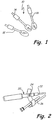
- Fig. 1
- einen Satz von Ellipsenplatten zur Bestimmung der Bohrgröße und des Bohrwinkels,
- Fig. 2
- ein Winkelführungsgerät, dessen Fixierfortsatz durch eine Ellipsenplatte gebildet ist,
- Fig. 3
- ein Winkelführungsgerät, bei dem der Fixierfortsatz durch einen Fixierdom für Kniegelenke gebildet ist,
- Fig. 4
- eine Bohrführung,
- Fig. 5
- eine Bohrführung mit Zylinderbohrer,
- Fig. 6
- eine zweite perspektivische Ansicht der Bohrführung mit Zylinderbohrer aus
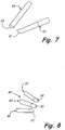
Figur 5 , - Fig. 7
- zwei Zylinderbohrer mit abgeschrägter Spitze in Seitenansicht,
- Fig. 8
- Zylinderbohrer mit abgeschrägter Spitze zum Handbetrieb,
- Fig. 9
- eine schematische Ansicht des Vortriebs des Zylinderbohrers mit abgeschrägter Spitze im Operationsgebiet,
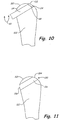
- Fig. 10/11
- eine schematische Darstellung des Ausstanzens und Ersetzen eines defekten Gelenkflächenbereichs, und
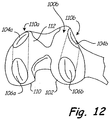
- Fig. 12
- eine perspektivische Ansicht zweier in einem Femur implantierter Implantate zur Restauration von Kniegelenksabschnitten .
- Fig. 13-16
- weitere Ausführungsformen erfindungsgemäßer Implantate.
-
Figur 1 zeigt drei Ellipsenplatten, welche durch einen schrägen Schnitt aus einem Kreiszylinder entstehen. Die Winkelabgabe aus den Ellipsenplatten geben dabei den Schnittwinkel relativ zu einer Querschnittsfläche zur Zylinderachse an. Dementsprechend bedingt eine große Winkelabweichung vom Zylinderquerschnitt eine entsprechend längere Ellipsenform und eine geringere Abweichung eine entsprechend kürzere Länge der Ellipse. Die Breite der Ellipse entspricht dem Zylinderdurchmesser. Der Satz an vorzusehenden Ellipsenplatten umfasst sowohl unterschiedliche Winkel als auch unterschiedliche Durchmesser, so dass alle Größen von Gelenkflächendefekten mit den Ellipsenplatten abgedeckt werden können. Die Ellipsenplatten werden derart über der defekten Gelenkstelle angeordnet, dass die defekte Gelenkstelle vollflächig überdeckt wird, zugleich aber möglichst wenig gesunde Gelenkfläche. Der Winkel und die Breite, d.h. der Durchmesser der Ellipsenplatte legen den Bohrwinkel und den Durchmesser des Bohrers fest, der zum Abtragen von Knochenmaterial verwendet wird. Der Knochenabtrag erfolgt hierbei in dem von der Ellipsenplatte angegebenen Winkel relativ zur Gelenkfläche, wobei der ausgebohrte bzw. ausgestanzte Zylinderbereich in der defekten Gelenkfläche mündet. Dieser ausgebohrte bzw. ausgeschnittene oder ausgestanzte Knochenbereich wird später durch ein Knochenersatzmaterial auf natürlicher Basis wie z. B. Hydroxylapatit oder durch keramische oder metallische Implantatmaterialien z. B. auf Titanbasis ersetzt, wobei das in die Gelenkfläche ragende Ende des Knochenersatzmaterials dann die ausgeschnittene defekte Gelenkfläche substituiert. - Anstelle der Ellipsenplatten ist es jedoch auch möglich, durch die Messung der Länge und der Breite der Defektstelle den korrekten Schneidwinkel und Bohrdurchmesser für das abzutragende Knochenmaterial zu bestimmen.
- Ferner umfasst die Anordnung zur partiellen Gelenkflächenrestauration ein Winkelführungsgerät, das es ermöglicht, entweder den Bohrer in dem gewünschten Winkel relativ zur Gelenkfläche durch den Knochen zu führen oder zum Setzen von Führungsdrähten, an welchen eine Bohrführung befestigt werden kann, die dann die Führungsaufgabe für den Bohrer in entsprechender Weise wahrnimmt. Das Bohrloch wird so gesetzt, dass es in dem vorher bestimmten Abstand und Winkel durch den Knochen führt und in der Defektstelle endet, womit durch den Bohrvorgang die Gelenkflächendefektstelle aus dem Knochen entfernt wird.
- Hierfür hat das Winkelführungsgerät 20 einen Fixierfortsatz 22, der in diesem Fall durch eine Ellipsenplatten aus
Figur 1 gebildet ist, einen Winkelstellmechanismus 24 und eine Führung 26 zum Setzen von Führungsdrähten in dem Knochen. Zusätzlich hat das Winkelstellgerät 20 zur besseren Handhabung an seinem hinteren Ende einen Handgriff 28. Der Fixierfortsatz 22 ist vorzugsweise lösbar in dem Winkelstellgerät 20 gehalten, so dass unterschiedliche Fixierfortsätze in das Winkelstellgerät 20 einsetzbar sind, wie dies beispielweise inFigur 3 gezeigt ist, bei welcher der Fixierfortsatz 30 durch einen Fixierdorn zum Einsatz in das Kniegelenk gebildet ist. DieFigur 3 zeigt zudem einen Führungsdraht 32, der durch die Führung 26 in dem Knochen gesetzt wird, um eine Bohrführung an dem Knochen zu fixieren, die beispielsweise inFigur 4 dargestellt ist. - Die Bohrführung 40 umfasst einen Anlagebereich 42 zur Anlage an den Knochen und zwei Führungslöcher 44, 46, die von Führungsdrähten 32 durchsetzbar sind. Die Führungsdrähte sind z.B. mittels des Winkelstellgerätes 20 der
Figuren 2 und3 im Knochen gesetzt worden. Die Bohrführung 40 ist insgesamt als Hohlzylinder ausgebildet mit einem inneren Zylinderbereich 48, in welchem ein Bohrer gemäß denFiguren 5 bis 8 geführt wird. Die Bohrführung 40 umfasst ferner eine Drehhülse 50, die innenseitig Spannelemente (nicht dargestellt) aufweist, um einen geführten Bohrer in einer definierten Position zu fixieren. -
Figur 5 zeigt eine Bohrführung 40 zusammen mit einem Zylinderbohrer 60, der eine Diamantkrone 62 aufweist. Der Zylinderbohrer 60 ist sehr dünnwandig und innen hohl, so dass das Knochenmaterial nur im Mantelbereich des Zylinderbohrers 60 geschnitten wird, während das abzutragende Material in dem Innenhohlraum des Bohrers verbleibt. Die Traumatisierung des Gewebes ist somit minimal. -
Figur 6 zeigt die gleiche Anordnung mit Bohrführung 40 und Zylinderbohrer 60 von schräg vorne. - Wenn der Knochen in einem schrägen Winkel angebohrt werden soll, wird vorzugsweise eine Oszillationsbohreinrichtung mit einem geringen Oszillationswinkel von maximal 10 ° insbesondere maximal 5 ° verwendet. In diesem Fall ist die Spitze der Zylinderbohrer 64, 66 vorzugsweise abgeschrägt 68, 70, so dass die durch die Schräge gebildete Ellipsenfläche des Bohrerkopfes am Ende des Bohrvorganges genau in der Gelenkebene endet, wodurch sichergestellt wird, dass beim Abtragen, d. h. Ausstanzen des Knochenmaterials der Bohrer mit seiner Kante nicht in das Gewebe zwischen den Gelenkflächen oder in die gegenüberliegende intakte Gelenkfläche einschneidet. Durch den geringen Oszillationswinkel im Zusammenhang mit der dem Schneidwinkel angepassten Schräge des Zylinderbohrers wird somit sichergestellt, dass das vordere Ende 68, 70 der Bohrer exakt in der Gelenkebene endet. Sollte das ausgestanzte Material dennoch an ein paar Fasern hängen, so ist vorzugsweise ein Satz 80 von Handbohrern 82 bis 86 (
Fig. 8 ) vorgesehen, deren schräge Spitze 88 bis 92 exakt der Schrägfläche der Bohrer 64, 66 ausFigur 7 und exakt der Ellipsenform der Ellipsenplatten ausFigur 1 entspricht. Durch die manuellen Bohrer 82 bis 86 kann somit das ausgestanzte Knochenmaterial schonend aus dem Operationsgebiet gelöst werden. - Nach dem Herausbohren und Herausnehmen des Knochenmaterials wird dann, wie es in
Figur 9 gezeigt ist, ein Implantat 100 in den Knochen 102 eingesetzt, wobei das Material des Implantats an der gelenkseitigen Stirnfläche 104 und an der Außenseite des Knochens 106 oberflächenbearbeitet wird, um zum einen die Gelenkfläche in Form und Glätte möglichst naturgetreu nachzubilden und zum anderen die Außenfläche des Knochens zur Vermeidung einer Traumatisierung des umgebenden Gewebes möglichst genau nachzubilden. - Der Vorgang des Ausbohrens mit der Oszillationsbohrvorrichtung und des Anschließenden Substituierens des ausgefrästen Knochenbereichs mit einem Implantat ist schematisch in den
Figuren 10 und 11 wiedergegeben. -
Fig. 10 zeigt einen Knochen 102 mit einer oberen Gelenkfläche 110 , z.B. entsprechend dem Kugelgelenk des Femurs. Mit einem Hohlzylinderbohrer 64 ausFig. 7 mit abgeschrägter Spitze 68 wird nun das abzutragende Knochenmaterial unter dem defekten Gelenkflächenbereich 112 ausgestanzt. Durch die Verwendung einer Oszillationsbohrvorrichtung 65 mit geringem Oszillationswinkel von etwa 5 Winkelgrad bleibt die Schräge 68 in etwa parallel zur Oberfläche des defekten Gelenkflächenabschnitts 112. Wenn nun die schräge Krone 68 der Hohlzylinderstanze 64 die Oberfläche 112 erreicht, liegt sie ziemlich genau in der Ebene des defekten Abschnitts 112 und traumatisiert umgebendes Gewebe des Gelenks nur minimal. - Gemäß
Fig. 11 wird nach dem Herausnehmen des zu ersetzenden Knochenmaterials 114 die dadurch entstandene zylindrische Bohrung im Knochen 102 durch ein Implantat 100 gefüllt, wie es z.B. inFig. 9 bereits gezeigt wurde. - Das Implantat umfasst einen zylindrischen Grundkörper 116, dessen abgewandte Stirnseiten 104 und 106 den defekten Gelenkflächenbereich 112 und die Knochenperipherie substituieren. Die zum Gelenk weisende Stirnseite 104 des Implantats 100 wird oberflächenbehandelt, um die Geometrie und Oberflächenbeschaffenheit des umgebenden Gelenkflächenbereichs 110 so gut wie möglich nachzubilden. Es sind auch an sich bekannte Formnachbildungsverfahren anwendbar, um die Stirnseite 104 der Gelenkfläche aus dem Gelenkflächenbereich 112 so gut wie möglich nachzubilden. Auch die zur Knochenperipherie weisende Stirnseite 106 des Implantats 100 wird oberflächenbehandelt, um einen homogenen und gewebeverträglichen Abschluss mit der umgebenden Knochenoberfläche zu erzeugen.
-
Fig. 12 zeigt zwei Implantate 100a, 100b, die in einem Kniegelenk eines Femurknochens 102 implantiert sind. Die Implantate 100a,b bestehen aus einer Titanlegierung, die für Gelenkimplantate üblich ist. Die ersten Stirnseiten 104a,b der Implantate bilden einen Teil der Gelenkfläche 112 und sind derart oberflächenbehandelt, dass die fluchtend mit der umgebenden Gelenkfläche 112 das Gelenk wieder in seiner ursprünglichen Funktionalität wiederherstellen. Die Implantate sitzen im Preßsitz in den im Knochen 102 ausgefrästen Löchern, womit sie gegen axiale Verschiebung auch bei starker Beanspruchung des Gelenks festgelegt sind. Hierbei ist anzumerken, dass durch die Tatsache, dass die Stirnflächen 104a,b der Implantate 100a,b relativ zur Zylinderachse des Grundkörpers 106b in einem Winkel ungleich 90 Grad geneigt sind, zu einer nicht axialen Krafteinleitung auf das Implantat führt. In der Figur ist sehr schön der zylindrische Grundkörper 106b des rechten Implantats 100b zu sehen. -
Fig. 13 zeigt sehr schematisch ein Implantat 120 mit einem zylindrischen Grundkörper 122, bei dem die Gelenkersatzfläche 124 im Peripheriebereich des Grundkörpers 122, d.h. durch Abtragung von Material im Peripheriebereich, ausgebildet ist. Die Stirnseite 126, 128 schließen mit der Peripherie des Knochens 102 im Gelenkbereich ab. Das Implantat besteht vorzugsweise aus Titanlegierung, kann aber auch aus einem anderen der genannten Knochen und/oder Gelenkersatzstoffe bestehen. Insbesondere kann die Gelenkersatzfläche 124 auf einem separat in den Grundkörper 122 einzusetzenden Teil angeordnet sein, das ein spezielles Gelenkersatzmaterial ist. -
Fig. 14 zeigt ein Implantat 130 mit einem zylindrischen Grundkörper 132, das einen Adapter für ein Gelenkflächenersatzteil 134 aufweist, auf dem die Gelenkersatzfläche 136 ausgebildet ist. Als Adaptertechnik können Stifte, Schrauben Presssitz und andere an sich bekannte Techniken dienen. Der Vorteil dieser Ausbildungsform besteht darin, dass der Grundkörper 132 aus optimiertem Knochenersatzwerkstoff bestehen kann, während das Gelenkflächenersatzteil 134 für die Bildung der Gelenkfläche optimiert ist. -
Fig. 15 zeigt ein kugeliges Implantat 140, das in eine kreiszylindrisches Bohrloch im Gelenkbereich des Knochens 102 eingesetzt ist. Die Gelenkersatzfläche 142 wurde durch Abtragen aus der Kugelperipherie erstellt. - Die
Figuren 16a und 16b zeigen ein Implantat 150 im Kieferknochen 152. Das Implantat besteht aus einem kreiszylindrischen Grundkörper 154, der mit seiner Längsachse horizontal und quer zum Kieferknochen eingesetzt wird. Der Grundkörper 154 hat einen Adapter 156, im einfachsten Fall eine Bohrung, in der ein Stift 158 zur Aufnahme einer Krone 160 aufgenommen ist. Der Grundkörper 154 besteht vorzugsweise aus Knochenersatzmaterial mit einer guten Gewebeverträglichkeit, welches insbesondere gut in den Knochen einwachsen kann. Der Stift und die Krone können aus herkömmlichen Dentalimplantatmaterialien bestehen. - Die in den obigen Figuren dargestellten Grundkörper sind vorzugsweise kreiszylindrisch, können jedoch auch andere Formen haben, wie z.B. Kegel bzw. Konus oder Zylinder mit nicht kreisrunder Grundfläche etc.
- Die in den Figuren dargestellten Beispiele sind nur zur Erläuterung des Erfindungsgegenstandes gedacht und sollen keinen schwenkenden Charakter bezüglich des Schutzbereiches mit sich bringen, der durch die nachfolgenden Ansprüche definiert wird.
- Selbstverständlich ist es möglich einzelne Merkmale der Erfindung einzeln oder in einer größeren Anzahl vorzusehen, z.B. die Führungsdrähte. Wenn ausgeführt ist, dass die durch die Anordnung vorgegebene Bohrachse in etwa den Mittelpunkt der defekten Gelenkfläche schneidet, so sind Abweichungen von wenigen mm, z.B. bis zu 5 mm tolerierbar.
Claims (12)
- Implantat (100, 100a, 100b) zum partiellen Ersatz von Gelenkflächen (112), bestehend aus einem zylindrischen Grundkörper (116, 122, 132) zum Einsatz in einen aus einem Knochen ausgenommenen Bereich mit einer Gelenkersatzfläche (124) zur Substitution des zu ersetzenden Gelenkflächenabschnitts, wobei der Grundkörper eine erste Stirnseite (104, 126), eine zweite Stirnseite (106, 128) und einen peripheren Bereich aufweist und wobei mindestens eine der Stirnseiten eine in einem Winkel ungleich 90° zur Zylinderachse verlaufende erste Stirnfläche aufweist, wobei die erste Stirnfläche als die Gelenkersatzfläche (104a, 104b) ausgebildet ist.
- Implantat (100) zum partiellen Ersatz von Gelenkflächen (112), bestehend aus einem zylindrischen Grundkörper (116, 122, 132) zum Einsatz in einen aus einem Knochen ausgenommenen Bereich mit einer Gelenkersatzfläche (124) zur Substitution des zu ersetzenden Gelenkflächenabschnitts, wobei der Grundkörper eine erste Stirnseite (104, 126), eine zweite Stirnseite (106, 128) und einen peripheren Bereich aufweist und wobei eine im peripheren Bereich durch Abtragen von Material des zylindrischen Grundkörpers ausgebildete Fläche als die Gelenkersatzfläche (124) ausgebildet ist.
- Implantat (100) nach einem der Ansprüche 1 bis 2, dadurch gekennzeichnet, dass der Grundkörper (116, 122, 132) kreiszylindrisch ausgebildet ist.
- Implantat (100) nach einem der Ansprüche 1 bis 3, wobei der Grundkörper (116, 122, 132) zum Einsatz in einem Stanz- oder Bohrbereich im Knochen ausgebildet ist.
- Implantat (100) nach Anspruch 1, 2, 3 oder 4, wobei die erste Fläche oder die im peripheren Bereich ausgebildete Gelenkersatzfläche gerade oder gekrümmt bzw. geformt ist.
- Implantat (100) nach einem der Ansprüche 1 bis 5, dadurch gekennzeichnet, dass die zweite Stirnseite (106) eine zweite Fläche zum Abschluss mit der Knochenperipherie aufweist.
- Implantat (100) nach Anspruch 6, wobei die zweite Fläche gerade oder gekrümmt bzw. geformt ist.
- Implantat (100) nach einem der Ansprüche 1 bis 7, dadurch gekennzeichnet, dass es einstückig hergestellt ist.
- Implantat (100) nach einem der vorhergehenden Ansprüche, dadurch gekennzeichnet, dass der Grundkörper aus einem Implantatwerkstoff oder Knochenersatzwerkstoff besteht.
- Implantat (100) nach einem der Ansprüche 1 bis 7, dadurch gekennzeichnet, dass die erste und/oder zweite Stirnfläche (104, 106) oder die im peripheren Bereich ausgebildete Fläche durch ein spezielles Gelenkflächenmaterial gebildet sind.
- Implantat (100) nach Anspruch 10, wobei das Gelenkflächenmaterial aus einem Material für künstliche Gelenke besteht, wie z.B. Keramik oder Titanlegierungen.
- Implantat (100) nach einem der vorhergehenden Ansprüche, dadurch gekennzeichnet, dass der Durchmesser des Grundkörpers (116) ein wenig größer als der aus dem Knochen ausgenommene Bereich ist, so dass das Implantat im Presssitz in den aus dem Knochen ausgenommenen Bereich einsetzbar ist.
Applications Claiming Priority (2)
| Application Number | Priority Date | Filing Date | Title |
|---|---|---|---|
| DE2002125217 DE10225217A1 (de) | 2002-06-06 | 2002-06-06 | Implantat und Anordnung zum insbesondere partiellen Ersatz von belasteten Flächen |
| EP03756969.6A EP1592360B1 (de) | 2002-06-06 | 2003-06-05 | Anordnung zum insbesondere partiellen ersatz von belasteten flächen |
Related Parent Applications (3)
| Application Number | Title | Priority Date | Filing Date |
|---|---|---|---|
| EP03756969.6A Division EP1592360B1 (de) | 2002-06-06 | 2003-06-05 | Anordnung zum insbesondere partiellen ersatz von belasteten flächen |
| EP03756969.6A Division-Into EP1592360B1 (de) | 2002-06-06 | 2003-06-05 | Anordnung zum insbesondere partiellen ersatz von belasteten flächen |
| EP03756969.6 Division | 2003-06-05 |
Publications (3)
| Publication Number | Publication Date |
|---|---|
| EP2583632A2 EP2583632A2 (de) | 2013-04-24 |
| EP2583632A3 EP2583632A3 (de) | 2014-04-02 |
| EP2583632B1 true EP2583632B1 (de) | 2018-05-09 |
Family
ID=29557612
Family Applications (3)
| Application Number | Title | Priority Date | Filing Date |
|---|---|---|---|
| EP12199263.0A Expired - Lifetime EP2583632B1 (de) | 2002-06-06 | 2003-06-05 | Implantat zum partiellen Ersatz von belasteten Flächen |
| EP20120199267 Withdrawn EP2581050A1 (de) | 2002-06-06 | 2003-06-05 | Implantat und Anordnung zum insbesondere partiellen Ersatz von belasteten Flächen |
| EP03756969.6A Expired - Lifetime EP1592360B1 (de) | 2002-06-06 | 2003-06-05 | Anordnung zum insbesondere partiellen ersatz von belasteten flächen |
Family Applications After (2)
| Application Number | Title | Priority Date | Filing Date |
|---|---|---|---|
| EP20120199267 Withdrawn EP2581050A1 (de) | 2002-06-06 | 2003-06-05 | Implantat und Anordnung zum insbesondere partiellen Ersatz von belasteten Flächen |
| EP03756969.6A Expired - Lifetime EP1592360B1 (de) | 2002-06-06 | 2003-06-05 | Anordnung zum insbesondere partiellen ersatz von belasteten flächen |
Country Status (4)
| Country | Link |
|---|---|
| US (2) | US9131990B2 (de) |
| EP (3) | EP2583632B1 (de) |
| DE (1) | DE10225217A1 (de) |
| WO (1) | WO2003103535A2 (de) |
Families Citing this family (2)
| Publication number | Priority date | Publication date | Assignee | Title |
|---|---|---|---|---|
| IL223577A0 (en) * | 2012-12-12 | 2013-02-03 | Husam Yassin | Anchored dental implants |
| EP3773298A1 (de) | 2018-04-03 | 2021-02-17 | Convergent Dental, Inc. | Lasersystem für chirurgische anwendungen |
Citations (2)
| Publication number | Priority date | Publication date | Assignee | Title |
|---|---|---|---|---|
| US3879767A (en) * | 1972-01-26 | 1975-04-29 | Cutter Lab | Prosthesis for articulating body structures |
| US4784661A (en) * | 1985-11-22 | 1988-11-15 | Robert Beckenbaugh | Total wrist prosthesis |
Family Cites Families (45)
| Publication number | Priority date | Publication date | Assignee | Title |
|---|---|---|---|---|
| US1179271A (en) * | 1914-02-21 | 1916-04-11 | William A Berger | Telescope-support. |
| DE2914737C3 (de) * | 1979-04-11 | 1981-12-10 | Feldmühle AG, 4000 Düsseldorf | Hüftkopf-Kappen-Endoprothese |
| DE2953575C2 (de) * | 1979-04-11 | 1983-01-05 | Feldmühle AG, 4000 Düsseldorf | Hüftkopf-Kappen-Endoprothese |
| US4479271A (en) | 1981-10-26 | 1984-10-30 | Zimmer, Inc. | Prosthetic device adapted to promote bone/tissue ingrowth |
| US4911720A (en) * | 1983-03-10 | 1990-03-27 | Collier John P | Particular surface replacement prosthesis |
| US4531917A (en) * | 1984-04-02 | 1985-07-30 | Linkow Leonard I | Detachable post for an osseous implant |
| AT390183B (de) * | 1985-07-16 | 1990-03-26 | Boehler Gmbh | Knochenimplantat fuer endoprothesen |
| US4696298A (en) * | 1985-11-19 | 1987-09-29 | Storz Instrument Company | Vitrectomy cutting mechanism |
| US4811632A (en) * | 1986-02-04 | 1989-03-14 | Othy, Inc. | Method of producing an acetabular reamer cup |
| US5194066A (en) * | 1988-01-11 | 1993-03-16 | Boehringer Mannheim Corporation | Modular joint prosthesis |
| CA2031571A1 (en) * | 1990-12-05 | 1992-06-06 | The University Of British Columbia | Antibiotic loaded joint prosthesis |
| US5320115A (en) * | 1991-01-16 | 1994-06-14 | Applied Biological Concepts | Method and apparatus for arthroscopic knee surgery |
| GB9102348D0 (en) * | 1991-02-04 | 1991-03-20 | Inst Of Orthopaedics The | Prosthesis for knee replacement |
| US6013853A (en) * | 1992-02-14 | 2000-01-11 | The University Of Texas System | Continuous release polymeric implant carrier |
| US5326364A (en) * | 1992-12-16 | 1994-07-05 | Wright Medical Technology, Inc. | Trapezial implant |
| FR2700462B1 (fr) | 1993-01-19 | 1995-04-21 | Medimplant | Appareillage d'implantation d'une prothèse articulaire. |
| US5423330A (en) * | 1993-03-10 | 1995-06-13 | The University Of Miami | Capsule suction punch instrument and method of use |
| US5368051A (en) * | 1993-06-30 | 1994-11-29 | Dunn; Allan R. | Method of regenerating articular cartilage |
| DE69533580T2 (de) | 1994-01-13 | 2006-02-23 | McGuire, David A., Anchorage | Allogenes oder synthetisches knochenkompositimplantat |
| US5570700A (en) * | 1994-10-03 | 1996-11-05 | Vogeler; Douglas M. | Elliptical biopsy punch |
| US5591170A (en) * | 1994-10-14 | 1997-01-07 | Genesis Orthopedics | Intramedullary bone cutting saw |
| US5782835A (en) | 1995-03-07 | 1998-07-21 | Innovasive Devices, Inc. | Apparatus and methods for articular cartilage defect repair |
| DE19512854C1 (de) * | 1995-04-06 | 1996-08-01 | Eska Medical Gmbh & Co | Fingergelenk |
| US5895426A (en) * | 1996-09-06 | 1999-04-20 | Osteotech, Inc. | Fusion implant device and method of use |
| US5881733A (en) * | 1996-09-13 | 1999-03-16 | Depuy Orthopaedic Technology, Inc. | Technique for osteocartilaginous transplantation in a mammalian joint |
| US5921987A (en) * | 1996-09-13 | 1999-07-13 | Depuy Orthopaedic Technology, Inc. | Articular cartilage transplant instrument set |
| US5772664A (en) | 1997-02-12 | 1998-06-30 | Wright Medical Technology, Inc. | Instrument for harvesting bone grafts having substantially cylindrical bone plugs |
| DE19721661A1 (de) | 1997-05-23 | 1998-11-26 | Zimmer Markus | Knochen- und Knorpel Ersatzstrukturen |
| WO1999021497A1 (de) * | 1997-10-27 | 1999-05-06 | Sulzer Orthopädie Ag | Verfahren und instrumente für die reparatur von endochondralen und osteochondralen defekten |
| DE69836592T2 (de) * | 1997-11-18 | 2007-10-11 | Biomedical Engineering Trust I | Führungsvorrichtung für antero-posteriore femorale resektion mit einem satz von abnehmbaren spannhülsen |
| US6039568A (en) * | 1998-06-02 | 2000-03-21 | Hinds; Kenneth F. | Tooth shaped dental implants |
| JP2920167B1 (ja) | 1998-06-10 | 1999-07-19 | 英卓 高 | 医療用ボーンプラグカッタ |
| DE19839950C1 (de) | 1998-09-02 | 2000-01-20 | Aesculap Ag & Co Kg | Instrument zur Entnahme von Knorpel-Knochen-Blöcken |
| ATE287686T1 (de) * | 1999-03-23 | 2005-02-15 | Zimmer Gmbh | Instrument und instrumentensatz zum einbringen eines osteochondralen transplantats |
| EP1038509B1 (de) * | 1999-03-23 | 2005-01-26 | Zimmer GmbH | Instrument und Instrumentensatz zum Einbringen eines osteochondralen Transplantats |
| US6284002B1 (en) * | 1999-05-27 | 2001-09-04 | Nicholas G. Sotereanos | Proximal femoral replacement implant and method of implanting the same |
| US6200322B1 (en) * | 1999-08-13 | 2001-03-13 | Sdgi Holdings, Inc. | Minimal exposure posterior spinal interbody instrumentation and technique |
| GB9925956D0 (en) * | 1999-11-02 | 1999-12-29 | Novarticulate Bv | Joint prostheses |
| US6923650B2 (en) * | 2000-02-29 | 2005-08-02 | Hans Gustav Kurer | Guide post for trephine |
| WO2001080772A1 (en) * | 2000-04-21 | 2001-11-01 | Behrooz Tohidi | Wear-resistant artificial joint |
| US6375658B1 (en) * | 2000-04-28 | 2002-04-23 | Smith & Nephew, Inc. | Cartilage grafting |
| EP1159923B1 (de) * | 2000-05-31 | 2005-06-01 | Karl Fritz Reich | Chirurgischer Werkzeug-Set |
| DE20019026U1 (de) | 2000-11-08 | 2002-03-28 | Synthes AG Chur, Chur, Graubünden | Vorrichtung zur Fixierung eines Implantates |
| US6730094B2 (en) * | 2002-01-14 | 2004-05-04 | Symmetry Medical Usa, Inc. | Cutting edges for reamers and a method for making same |
| GB0319257D0 (en) * | 2003-08-15 | 2003-09-17 | Finsbury Dev Ltd | Surgical instruments and computer programs for use therewith |
-
2002
- 2002-06-06 DE DE2002125217 patent/DE10225217A1/de not_active Withdrawn
-
2003
- 2003-06-05 US US10/545,442 patent/US9131990B2/en not_active Expired - Fee Related
- 2003-06-05 WO PCT/DE2003/001880 patent/WO2003103535A2/de not_active Ceased
- 2003-06-05 EP EP12199263.0A patent/EP2583632B1/de not_active Expired - Lifetime
- 2003-06-05 EP EP20120199267 patent/EP2581050A1/de not_active Withdrawn
- 2003-06-05 EP EP03756969.6A patent/EP1592360B1/de not_active Expired - Lifetime
-
2015
- 2015-04-30 US US14/701,105 patent/US20150335433A1/en not_active Abandoned
Patent Citations (2)
| Publication number | Priority date | Publication date | Assignee | Title |
|---|---|---|---|---|
| US3879767A (en) * | 1972-01-26 | 1975-04-29 | Cutter Lab | Prosthesis for articulating body structures |
| US4784661A (en) * | 1985-11-22 | 1988-11-15 | Robert Beckenbaugh | Total wrist prosthesis |
Also Published As
| Publication number | Publication date |
|---|---|
| US9131990B2 (en) | 2015-09-15 |
| EP1592360A2 (de) | 2005-11-09 |
| EP2583632A3 (de) | 2014-04-02 |
| EP1592360B1 (de) | 2014-03-12 |
| WO2003103535A2 (de) | 2003-12-18 |
| WO2003103535A3 (de) | 2004-10-14 |
| EP2581050A1 (de) | 2013-04-17 |
| US20150335433A1 (en) | 2015-11-26 |
| US20060015189A1 (en) | 2006-01-19 |
| EP2583632A2 (de) | 2013-04-24 |
| DE10225217A1 (de) | 2003-12-18 |
Similar Documents
| Publication | Publication Date | Title |
|---|---|---|
| DE69113990T2 (de) | Chirurgisches instrument. | |
| DE69729140T2 (de) | Instrumentarium für die Einsetzung eines chirurgischen Implantats | |
| DE602004006471T2 (de) | Metatarsalphalangeale Vollprothese und Hilfsgerät zum Einsetzen einer solchen Prothese. | |
| DE69720803T2 (de) | Raspel zum bearbeiten eines markkanals eines knochens | |
| DE60311289T2 (de) | Fräsvorrichtung | |
| EP0915680B1 (de) | Vorrichtung zur herstellung von endochondralen oder osteochondralen bohrungen | |
| DE19713416B4 (de) | Führungsvorrichtung für ein Zwischenwirbelimplantat | |
| EP1589909B1 (de) | Zwischenwirbelimplantat | |
| DE602005002951T2 (de) | Massgefertigte implantierbare chirurgische führung und zugehöriges fräswerkzeug und herstellungsverfahren | |
| EP0622056A2 (de) | Implantierbares Verankerungsorgan zur Aufnahme von Prothesen u.dgl. | |
| DE2823406A1 (de) | Kuenstliches ellbogengelenk | |
| EP0927001A1 (de) | Zahnmedizinisches implantat, schablone zum einsetzen eines zahnmedizinischen implantats und verfahren zum herstellen von diesen | |
| DE20022673U1 (de) | Schraubverbindung für die Osteosynthese | |
| DE102009031269A1 (de) | Vorrichtung und Verfahren zur In-situ-Fräsung von Gelenkflächen | |
| DE2834297B2 (de) | Vorrichtung zum Bearbeiten eines endseitig mit einer Prothesenkappe zu versehenden Knochens | |
| WO2001062179A1 (de) | Vorrichtung mit einem knochenfräser | |
| WO2012143444A1 (de) | Instrumentarium zum einsetzen einer gelenkprothese, insbesondere knieprothese | |
| DE69634255T2 (de) | Elemente für gelenkprothese und verfahren zu deren herstellung | |
| DE69738227T2 (de) | Bohrapparat zum Einbetten eines Implantates in Knochengewebe | |
| DE202009019083U1 (de) | Implantat für den Einsatz in den Kieferknochen, Prothesenstütze und Implantatsystem | |
| DE2349357A1 (de) | Pfannenbefestigung einer kugelfoermigen gelenkpfanne aus einem keramischen werkstoff | |
| WO2007006258A1 (de) | Fräsvorrichtung zur entnahme von gewebe um ein implantat und bohrschablone | |
| DE2628929A1 (de) | Innenknochiges zahnimplantat | |
| EP0279075A2 (de) | Bohrer zur Präparation von Zähnen | |
| EP2583632B1 (de) | Implantat zum partiellen Ersatz von belasteten Flächen |
Legal Events
| Date | Code | Title | Description |
|---|---|---|---|
| PUAI | Public reference made under article 153(3) epc to a published international application that has entered the european phase |
Free format text: ORIGINAL CODE: 0009012 |
|
| AC | Divisional application: reference to earlier application |
Ref document number: 1592360 Country of ref document: EP Kind code of ref document: P |
|
| AK | Designated contracting states |
Kind code of ref document: A2 Designated state(s): AT BE BG CH CY CZ DE DK EE ES FI FR GB GR HU IE IT LI LU MC NL PT RO SE SI SK TR |
|
| PUAL | Search report despatched |
Free format text: ORIGINAL CODE: 0009013 |
|
| AK | Designated contracting states |
Kind code of ref document: A3 Designated state(s): AT BE BG CH CY CZ DE DK EE ES FI FR GB GR HU IE IT LI LU MC NL PT RO SE SI SK TR |
|
| RIC1 | Information provided on ipc code assigned before grant |
Ipc: A61C 8/00 20060101ALI20140227BHEP Ipc: A61B 17/16 20060101AFI20140227BHEP Ipc: A61F 2/30 20060101ALI20140227BHEP Ipc: A61C 1/08 20060101ALI20140227BHEP Ipc: A61B 17/17 20060101ALI20140227BHEP |
|
| 17P | Request for examination filed |
Effective date: 20141002 |
|
| RBV | Designated contracting states (corrected) |
Designated state(s): AT BE BG CH CY CZ DE DK EE ES FI FR GB GR HU IE IT LI LU MC NL PT RO SE SI SK TR |
|
| 17Q | First examination report despatched |
Effective date: 20150311 |
|
| GRAP | Despatch of communication of intention to grant a patent |
Free format text: ORIGINAL CODE: EPIDOSNIGR1 |
|
| INTG | Intention to grant announced |
Effective date: 20171018 |
|
| RAP1 | Party data changed (applicant data changed or rights of an application transferred) |
Owner name: KARL STORZ SE & CO. KG |
|
| GRAS | Grant fee paid |
Free format text: ORIGINAL CODE: EPIDOSNIGR3 |
|
| GRAA | (expected) grant |
Free format text: ORIGINAL CODE: 0009210 |
|
| RAP1 | Party data changed (applicant data changed or rights of an application transferred) |
Owner name: MEDARTIS MEDIZINPRODUKTE UND FORSCHUNG AG |
|
| AC | Divisional application: reference to earlier application |
Ref document number: 1592360 Country of ref document: EP Kind code of ref document: P |
|
| AK | Designated contracting states |
Kind code of ref document: B1 Designated state(s): AT BE BG CH CY CZ DE DK EE ES FI FR GB GR HU IE IT LI LU MC NL PT RO SE SI SK TR |
|
| REG | Reference to a national code |
Ref country code: GB Ref legal event code: FG4D Free format text: NOT ENGLISH |
|
| REG | Reference to a national code |
Ref country code: CH Ref legal event code: EP Ref country code: AT Ref legal event code: REF Ref document number: 996793 Country of ref document: AT Kind code of ref document: T Effective date: 20180515 |
|
| REG | Reference to a national code |
Ref country code: IE Ref legal event code: FG4D Free format text: LANGUAGE OF EP DOCUMENT: GERMAN |
|
| REG | Reference to a national code |
Ref country code: DE Ref legal event code: R096 Ref document number: 50315753 Country of ref document: DE |
|
| REG | Reference to a national code |
Ref country code: NL Ref legal event code: MP Effective date: 20180509 |
|
| PG25 | Lapsed in a contracting state [announced via postgrant information from national office to epo] |
Ref country code: FI Free format text: LAPSE BECAUSE OF FAILURE TO SUBMIT A TRANSLATION OF THE DESCRIPTION OR TO PAY THE FEE WITHIN THE PRESCRIBED TIME-LIMIT Effective date: 20180509 Ref country code: BG Free format text: LAPSE BECAUSE OF FAILURE TO SUBMIT A TRANSLATION OF THE DESCRIPTION OR TO PAY THE FEE WITHIN THE PRESCRIBED TIME-LIMIT Effective date: 20180809 Ref country code: SE Free format text: LAPSE BECAUSE OF FAILURE TO SUBMIT A TRANSLATION OF THE DESCRIPTION OR TO PAY THE FEE WITHIN THE PRESCRIBED TIME-LIMIT Effective date: 20180509 Ref country code: ES Free format text: LAPSE BECAUSE OF FAILURE TO SUBMIT A TRANSLATION OF THE DESCRIPTION OR TO PAY THE FEE WITHIN THE PRESCRIBED TIME-LIMIT Effective date: 20180509 |
|
| PG25 | Lapsed in a contracting state [announced via postgrant information from national office to epo] |
Ref country code: NL Free format text: LAPSE BECAUSE OF FAILURE TO SUBMIT A TRANSLATION OF THE DESCRIPTION OR TO PAY THE FEE WITHIN THE PRESCRIBED TIME-LIMIT Effective date: 20180509 Ref country code: GR Free format text: LAPSE BECAUSE OF FAILURE TO SUBMIT A TRANSLATION OF THE DESCRIPTION OR TO PAY THE FEE WITHIN THE PRESCRIBED TIME-LIMIT Effective date: 20180810 |
|
| PG25 | Lapsed in a contracting state [announced via postgrant information from national office to epo] |
Ref country code: EE Free format text: LAPSE BECAUSE OF FAILURE TO SUBMIT A TRANSLATION OF THE DESCRIPTION OR TO PAY THE FEE WITHIN THE PRESCRIBED TIME-LIMIT Effective date: 20180509 Ref country code: RO Free format text: LAPSE BECAUSE OF FAILURE TO SUBMIT A TRANSLATION OF THE DESCRIPTION OR TO PAY THE FEE WITHIN THE PRESCRIBED TIME-LIMIT Effective date: 20180509 Ref country code: CZ Free format text: LAPSE BECAUSE OF FAILURE TO SUBMIT A TRANSLATION OF THE DESCRIPTION OR TO PAY THE FEE WITHIN THE PRESCRIBED TIME-LIMIT Effective date: 20180509 Ref country code: DK Free format text: LAPSE BECAUSE OF FAILURE TO SUBMIT A TRANSLATION OF THE DESCRIPTION OR TO PAY THE FEE WITHIN THE PRESCRIBED TIME-LIMIT Effective date: 20180509 Ref country code: SK Free format text: LAPSE BECAUSE OF FAILURE TO SUBMIT A TRANSLATION OF THE DESCRIPTION OR TO PAY THE FEE WITHIN THE PRESCRIBED TIME-LIMIT Effective date: 20180509 |
|
| REG | Reference to a national code |
Ref country code: CH Ref legal event code: PL |
|
| REG | Reference to a national code |
Ref country code: DE Ref legal event code: R097 Ref document number: 50315753 Country of ref document: DE |
|
| PG25 | Lapsed in a contracting state [announced via postgrant information from national office to epo] |
Ref country code: IT Free format text: LAPSE BECAUSE OF FAILURE TO SUBMIT A TRANSLATION OF THE DESCRIPTION OR TO PAY THE FEE WITHIN THE PRESCRIBED TIME-LIMIT Effective date: 20180509 |
|
| REG | Reference to a national code |
Ref country code: BE Ref legal event code: MM Effective date: 20180630 |
|
| PLBE | No opposition filed within time limit |
Free format text: ORIGINAL CODE: 0009261 |
|
| STAA | Information on the status of an ep patent application or granted ep patent |
Free format text: STATUS: NO OPPOSITION FILED WITHIN TIME LIMIT |
|
| REG | Reference to a national code |
Ref country code: IE Ref legal event code: MM4A |
|
| PG25 | Lapsed in a contracting state [announced via postgrant information from national office to epo] |
Ref country code: LU Free format text: LAPSE BECAUSE OF NON-PAYMENT OF DUE FEES Effective date: 20180605 Ref country code: MC Free format text: LAPSE BECAUSE OF FAILURE TO SUBMIT A TRANSLATION OF THE DESCRIPTION OR TO PAY THE FEE WITHIN THE PRESCRIBED TIME-LIMIT Effective date: 20180509 |
|
| 26N | No opposition filed |
Effective date: 20190212 |
|
| GBPC | Gb: european patent ceased through non-payment of renewal fee |
Effective date: 20180809 |
|
| PG25 | Lapsed in a contracting state [announced via postgrant information from national office to epo] |
Ref country code: LI Free format text: LAPSE BECAUSE OF NON-PAYMENT OF DUE FEES Effective date: 20180630 Ref country code: CH Free format text: LAPSE BECAUSE OF NON-PAYMENT OF DUE FEES Effective date: 20180630 Ref country code: IE Free format text: LAPSE BECAUSE OF NON-PAYMENT OF DUE FEES Effective date: 20180605 Ref country code: FR Free format text: LAPSE BECAUSE OF NON-PAYMENT OF DUE FEES Effective date: 20180630 |
|
| PG25 | Lapsed in a contracting state [announced via postgrant information from national office to epo] |
Ref country code: BE Free format text: LAPSE BECAUSE OF NON-PAYMENT OF DUE FEES Effective date: 20180630 Ref country code: SI Free format text: LAPSE BECAUSE OF FAILURE TO SUBMIT A TRANSLATION OF THE DESCRIPTION OR TO PAY THE FEE WITHIN THE PRESCRIBED TIME-LIMIT Effective date: 20180509 |
|
| REG | Reference to a national code |
Ref country code: AT Ref legal event code: MM01 Ref document number: 996793 Country of ref document: AT Kind code of ref document: T Effective date: 20180605 |
|
| PG25 | Lapsed in a contracting state [announced via postgrant information from national office to epo] |
Ref country code: GB Free format text: LAPSE BECAUSE OF NON-PAYMENT OF DUE FEES Effective date: 20180809 |
|
| PG25 | Lapsed in a contracting state [announced via postgrant information from national office to epo] |
Ref country code: AT Free format text: LAPSE BECAUSE OF NON-PAYMENT OF DUE FEES Effective date: 20180605 |
|
| PG25 | Lapsed in a contracting state [announced via postgrant information from national office to epo] |
Ref country code: TR Free format text: LAPSE BECAUSE OF FAILURE TO SUBMIT A TRANSLATION OF THE DESCRIPTION OR TO PAY THE FEE WITHIN THE PRESCRIBED TIME-LIMIT Effective date: 20180509 |
|
| PG25 | Lapsed in a contracting state [announced via postgrant information from national office to epo] |
Ref country code: PT Free format text: LAPSE BECAUSE OF FAILURE TO SUBMIT A TRANSLATION OF THE DESCRIPTION OR TO PAY THE FEE WITHIN THE PRESCRIBED TIME-LIMIT Effective date: 20180509 Ref country code: HU Free format text: LAPSE BECAUSE OF FAILURE TO SUBMIT A TRANSLATION OF THE DESCRIPTION OR TO PAY THE FEE WITHIN THE PRESCRIBED TIME-LIMIT; INVALID AB INITIO Effective date: 20030605 |
|
| PG25 | Lapsed in a contracting state [announced via postgrant information from national office to epo] |
Ref country code: CY Free format text: LAPSE BECAUSE OF FAILURE TO SUBMIT A TRANSLATION OF THE DESCRIPTION OR TO PAY THE FEE WITHIN THE PRESCRIBED TIME-LIMIT Effective date: 20180509 |
|
| PGFP | Annual fee paid to national office [announced via postgrant information from national office to epo] |
Ref country code: DE Payment date: 20211229 Year of fee payment: 19 |
|
| REG | Reference to a national code |
Ref country code: DE Ref legal event code: R119 Ref document number: 50315753 Country of ref document: DE |
|
| PG25 | Lapsed in a contracting state [announced via postgrant information from national office to epo] |
Ref country code: DE Free format text: LAPSE BECAUSE OF NON-PAYMENT OF DUE FEES Effective date: 20230103 |