EP2583894A2 - Luftfahrzeugkabine, die die Aufnahme von Passagieren auf mehreren Ebenen erlaubt, und entsprechendes Luftfahrzeug - Google Patents
Luftfahrzeugkabine, die die Aufnahme von Passagieren auf mehreren Ebenen erlaubt, und entsprechendes Luftfahrzeug Download PDFInfo
- Publication number
- EP2583894A2 EP2583894A2 EP12188948.9A EP12188948A EP2583894A2 EP 2583894 A2 EP2583894 A2 EP 2583894A2 EP 12188948 A EP12188948 A EP 12188948A EP 2583894 A2 EP2583894 A2 EP 2583894A2
- Authority
- EP
- European Patent Office
- Prior art keywords
- zone
- bridge
- aircraft
- passengers
- floor
- Prior art date
- Legal status (The legal status is an assumption and is not a legal conclusion. Google has not performed a legal analysis and makes no representation as to the accuracy of the status listed.)
- Withdrawn
Links
- OKTJSMMVPCPJKN-UHFFFAOYSA-N Carbon Chemical compound [C] OKTJSMMVPCPJKN-UHFFFAOYSA-N 0.000 claims description 5
- 229910052799 carbon Inorganic materials 0.000 claims description 4
- 239000002131 composite material Substances 0.000 claims description 3
- 239000003351 stiffener Substances 0.000 claims description 3
- 241000273930 Brevoortia tyrannus Species 0.000 description 8
- 210000000038 chest Anatomy 0.000 description 3
- 239000012530 fluid Substances 0.000 description 3
- 238000000926 separation method Methods 0.000 description 3
- 239000000463 material Substances 0.000 description 2
- 235000012054 meals Nutrition 0.000 description 2
- 239000004677 Nylon Substances 0.000 description 1
- 230000004308 accommodation Effects 0.000 description 1
- 238000004873 anchoring Methods 0.000 description 1
- 230000000712 assembly Effects 0.000 description 1
- 238000000429 assembly Methods 0.000 description 1
- 238000004140 cleaning Methods 0.000 description 1
- 235000013305 food Nutrition 0.000 description 1
- 238000009434 installation Methods 0.000 description 1
- 230000010354 integration Effects 0.000 description 1
- 239000002184 metal Substances 0.000 description 1
- 238000000465 moulding Methods 0.000 description 1
- 229920001778 nylon Polymers 0.000 description 1
- 230000000284 resting effect Effects 0.000 description 1
Images



Classifications
-
- B—PERFORMING OPERATIONS; TRANSPORTING
- B64—AIRCRAFT; AVIATION; COSMONAUTICS
- B64D—EQUIPMENT FOR FITTING IN OR TO AIRCRAFT; FLIGHT SUITS; PARACHUTES; ARRANGEMENT OR MOUNTING OF POWER PLANTS OR PROPULSION TRANSMISSIONS IN AIRCRAFT
- B64D9/00—Equipment for handling freight; Equipment for facilitating passenger embarkation or the like
-
- B—PERFORMING OPERATIONS; TRANSPORTING
- B64—AIRCRAFT; AVIATION; COSMONAUTICS
- B64C—AEROPLANES; HELICOPTERS
- B64C1/00—Fuselages; Constructional features common to fuselages, wings, stabilising surfaces or the like
- B64C1/18—Floors
-
- B—PERFORMING OPERATIONS; TRANSPORTING
- B64—AIRCRAFT; AVIATION; COSMONAUTICS
- B64D—EQUIPMENT FOR FITTING IN OR TO AIRCRAFT; FLIGHT SUITS; PARACHUTES; ARRANGEMENT OR MOUNTING OF POWER PLANTS OR PROPULSION TRANSMISSIONS IN AIRCRAFT
- B64D11/00—Passenger or crew accommodation; Flight-deck installations not otherwise provided for
-
- B—PERFORMING OPERATIONS; TRANSPORTING
- B64—AIRCRAFT; AVIATION; COSMONAUTICS
- B64C—AEROPLANES; HELICOPTERS
- B64C1/00—Fuselages; Constructional features common to fuselages, wings, stabilising surfaces or the like
- B64C2001/0018—Fuselages; Constructional features common to fuselages, wings, stabilising surfaces or the like comprising two decks adapted for carrying passengers only
- B64C2001/0027—Fuselages; Constructional features common to fuselages, wings, stabilising surfaces or the like comprising two decks adapted for carrying passengers only arranged one above the other
Definitions
- the present invention relates to an aircraft cabin for accommodating passengers on several levels, and a corresponding aircraft.
- the field of the present invention is the interior layout of an aircraft fuselage intended for the commercial transport of passengers.
- aircraft intended to carry a relatively large number of passengers, for example greater than 100.
- the conventional structure inside an aircraft for the transport of passengers generally comprises a fuselage of substantially circular cylindrical shape inside which is disposed a horizontal bridge (when the aircraft is on the ground) which serves as a one side, floor for a cabin for receiving passengers, and, secondly, to achieve a separation between a cargo hold for the transport of luggage and containers and the aforementioned cabin.
- a double deck is provided inside the fuselage. These are aircraft whose fuselage has a width and height -very important.
- the two decks are substantially flat and allow two superimposed cabins with a ceiling height of about 2.50 m each. They are connected by stairs and / or lifts.
- EP 2460727 describes an aircraft cabin comprising a first section comprising a lower bridge and an upper bridge, a second section comprising an intermediate bridge.
- a curved ramp connects the lower bridge to the intermediate bridge, and a curved ramp connects the intermediate bridge to the upper deck.
- the embarkation and disembarkation of the passengers can be carried out entirely from the intermediate bridge, provided with an access door.
- the three bridges are each consisting of a flat surface, which surfaces are substantially parallel.
- the hold height of these aircraft is usually intended to accommodate standard baggage containers (or other), known as LD1, LD2 or LD3. These containers have a height of 1.62 m.
- Another problem is the time required in the airport zone to embark and disembark passengers. Most often, there is not a good match between the characteristics of aisles (corridors) and those of access doors. The flow of passengers (theoretical) at the level of the access doors is often greater than that at the level of the corridors. The interior layout of such an aircraft therefore penalizes the time of call.
- the purpose of the present invention is therefore to provide a solution for increasing the capacity of an aircraft of a given size in number of passengers by optimizing the occupancy of the volume inside the fuselage of the aircraft.
- such an arrangement will also allow a more fluid flow of passengers inside the cabin of the aircraft.
- the present invention provides a cabin of an aircraft for accommodating passengers having a first bridge for the reception of passengers "a second bridge for the reception of passengers, superimposed on the first bridge, as well as at least one access door.
- the first bridge has at least a first zone having a substantially flat floor and being at an access door and at least a second zone having a floor offset in height relative to the first zone.
- at least one rectilinear ramp connects the first zone of the first bridge to the second zone of the first bridge, and at least one straight ramp connects the first zone of the first bridge to the second bridge.
- the second bridge preferably extends over most of the second zone of the first bridge.
- ramps connect the first zone of the first bridge on the one hand to the second zone of the first bridge and secondly to the second bridge .
- a ramp is preferably used with respect to a staircase, or possibly an elevator, because if its slope is limited, it does not form an obstacle and therefore does not penalize, or very little, the movement of passengers and / or passengers.
- service trolleys usually called trolleys in relation to a horizontal corridor.
- the cabin according to the invention differs from the cabin of EP2460727 in that its ramps are rectilinear.
- Each ramp preferably has a straight line, or alternatively follows a broken line (several portions of non-parallel lines).
- this configuration makes it possible to optimize the occupancy and layout of the cabin. Indeed, the volume around the ramps can be used to accommodate seats or storage. This volume is lost with the curved ramps proposed by EP2460727 .
- moving trolleys or wheeled luggage is easier on straight ramps than on curved ramps. So is even people, which reduces boarding / disembarking times and can be critical in the event of an emergency evacuation of the aircraft.
- the first zone of the first bridge has no passenger seat between the access door and the ramps.
- This first zone may then be exclusively a passage area and possibly a service area, which may include service furniture (called galleys) separated by corridors.
- galleys service furniture
- the passengers are then distributed, in the first zone of the first bridge, in a flow going to the second zone of the first bridge via a first ramp and a flow to the second bridge via a second ramp.
- the rectilinear ramps used in a booth according to the invention are advantageously such that they have a slope of about 20%, for example between 10 and 30% and preferably between 15 and 25% (here, for example, there is a difference in height of the order of 0.45 m to 0.75 m over a length measured longitudinally in the aircraft of 3 m or even 0.75 m to 1.25 m for a length of 5 m). This slope corresponds to a slope when the aircraft is on the ground and the decks are substantially horizontal.
- a cabin according to the invention comprises circulation corridors.
- each ramp (24) opens on a corridor and extends in the same direction as this one.
- corridors and ramps all extend in the direction of roll (or longitudinal direction) of the aircraft.
- the second zone (12) of the first bridge and the second bridge comprise columns of seats against the fuselage, unlike the cabin of EP2460727 which has corridors along the fuselage, that is to say at the place of greater curvature and lower height.
- the second zone (12) of the first bridge comprises two corridors 20 each separating a lateral zone of seats, which may comprise one or more columns of seats) and a central zone of seats preferably comprising several columns of seats,
- the first bridge has a third zone at the rear of its second zone and having a substantially plane floor being offset in height relative to the second zone of the first bridge.
- This embodiment makes it possible to have only one door at the rear of the aircraft whereas otherwise it would be advisable to provide a door at the level of the second zone of the first bridge and a door at the level of the second bridge.
- the third zone and the first zone are both advantageously substantially at the same level. It is thus possible to provide doors at the front and rear of the aircraft at the same level as well.
- the cabin schematically has a shape reminiscent of a hexagon: two opposite sides of the hexagon correspond to the passenger receiving areas - second deck and second area of the first deck - two other sides correspond to the entrances between the first area of the first bridge and the areas receiving the passengers and the last two sides correspond to the accesses between the third zone of the first bridge and the areas receiving the passengers.
- the second bridge it can be expected that it has a floor structure with a complex shaped shape having different longitudinal zones, extending longitudinally. disposed at different levels, these longitudinal areas being flat and connected by substantially vertical walls, flanking either seats or corridors.
- said zones extending the entire length of the second bridge or at least the first row of seats to the last.
- the difference in level between a longitudinal zone forming a corridor and a contiguous longitudinal zone receiving seats is less than 0.60m, so as to limit the height of travel that a passenger must cross (uphill or downhill) to to move from one zone to another and to avoid any fall in case precipitated evacuation.
- This embodiment is compact, allows for very diverse shapes and is therefore very well suited here to optimize the space of the cabin.
- a floor structure is original in itself and advantageous independently of the other features of the invention; it could also be used in other configurations of aircraft cabin layout (a single bridge, several bridges, with or without ramp, ...) and in particular in a known aircraft.
- the complex floor structure of the second bridge may be for example a molded structure made of a composite material based on carbon.
- the second bridge can then advantageously rest on intermediate pieces arranged laterally and bearing on the first bridge.
- the complex floor structure is for example such that it comprises at least three longitudinal zones each with a different level from that of another area considered. For better strength while maintaining a lower thickness, such a complex floor advantageously comprises transverse stiffeners.
- the available height between the second zone of the first bridge and the second bridge is preferably between 1.20 m and 2.20 m .
- the corresponding space is used to accommodate luggage for example.
- the corresponding space is for example used as a corridor.
- the second zone of the first bridge advantageously has a substantially plane floor. This embodiment is easier to achieve. It also corresponds to the shape of the "ceiling" of a bunker that is generally substantially flat.
- the present invention also relates to an aircraft intended for the transport of passengers, characterized in that it comprises an aircraft cabin as described above.
- the first bridge advantageously has a third zone having a substantially plane floor being offset in height relative to the second zone of the first bridge, and located at the rear of the aircraft.
- Such an aircraft conventionally comprises a wing.
- the latter is for example under the first bridge in the second zone when the height of the wing is limited.
- the first bridge advantageously has a third zone having a substantially plane floor being offset in height with respect to the second zone of the first bridge, and the third zone is located above the wing of the aircraft.
- Such an aircraft is then such that the first bridge has above the wing and behind it also a configuration having a first zone, a second zone and a third zone, the second zone being offset with respect to the first zone. zone and the third zone.
- the present invention is more particularly suitable for an aircraft as described above when said aircraft has a fuselage whose equivalent diameter is greater than 4.50 m.
- a single bridge extends from the cockpit to the rear of the aircraft forming a plane floor of a single level over the entire length of the aircraft.
- This bridge separates the fuselage into two zones, a lower zone used for the most part as a bunker for receiving luggage and / or freight an upper zone which is intended to accommodate, on the one hand, the cockpit for the piloting of the aircraft and, on the other hand, a cabin to accommodate passengers as comfortably as possible during their journey.
- the part of the fuselage which interests us more particularly in the present invention is located between the cockpit 4 and the rear cone 6.
- the fuselage generally has in this zone a cylindrical circular shape of substantially constant section. This area of the aircraft is intended conventionally to receive passengers, their luggage and possibly goods. It is also in this central zone of the fuselage of the aircraft that a wing 8 is attached to the fuselage.
- the fuselage at least in the part of interest, has a substantially circular cross section and that the wing 8 is attached to the fuselage in the lower position.
- the present invention is applicable to other fuselage sections, bilobed and / or other wing layouts.
- the present invention is more particularly intended for aircraft whose cross section, at the cabin receiving passengers, has an equivalent diameter of 4.5 m.
- the cross section of the fuselage has at this level a surface greater than or equal to the surface of a circular section of 4.5 m in diameter, that is to say a surface of the order of 16 m 2 or more.
- the cockpit 4 intended to accommodate a pilot and his co-pilot, is equipped with all the command and control instruments for piloting the aircraft. It is assumed here that this cockpit 4 is similar to a cockpit of the prior art, that is to say in the present example, the cockpit 4 is similar to a cockpit of A321 (registered trademark).
- This cockpit 4 then comprises a floor (not shown here).
- the floor of the cockpit 4, in an A321 (registered trademark), is integrated in the single bridge described above. Such a floor is found for example also in an aircraft according to the present invention.
- the first bridge of the aircraft has mainly three zones, a first zone 10 at the front of the fuselage, just behind the cockpit 4, a second zone 12 extending over most of the length of the aircraft cabin, and a third zone 14 located at the rear of the fuselage 2 possibly extending into the rear cone 6.
- the first zone 10 of the first bridge extends in the extension of the cockpit floor 4.
- a common structure forms for example the cockpit floor 4 and this first zone 10.
- first door 16 which is used for loading and unloading passengers.
- This first door 16 is for example similar to a first door of a registered trademark aircraft A321 and also called door type C. It could also be a larger door, such as for example an aircraft door called type A door.
- the positioning of the first door 16, for example compared to the fuselage 2 is also similar to what is known from the prior art. Of course, it is not beyond the scope of the present invention by modifying the structure of the first door of the aircraft and / or its positioning (as soon as the first door opens on the first zone of the first bridge).
- a passenger boarding the aircraft passes through the first door 16 and arrives on the first zone 10 of the first bridge.
- the second zone 12 of the first bridge is behind the first zone 10 and below it. It is in the form of a area whose upper surface is substantially flat and horizontal. It thus forms a floor that can accommodate seats 18 ( figure 2 ) which can be accessed through corridors 20 ( figure 2 ).
- the second zone 12 of the first bridge a structure substantially similar to a single aircraft bridge of the prior art.
- the space dedicated to luggage and / or goods is reduced in favor of the space available for the cabin, and therefore passengers and their comfort.
- the third zone 14 is also an area defining a substantially planar floor.
- This third zone disposed at the rear of the fuselage 2 is for example arranged at the same height as the first zone 10.
- the first zone 10 and the third zone 14 may correspond to the front part, respectively to the rear part of a single bridge of an aircraft of the prior art.
- the second bridge 22 As can be seen in the drawings, above the second zone 12 there is an upper structure, hereinafter referred to as the second bridge 22.
- the latter generally has a shape profiled along the longitudinal axis (roll axis) of the aircraft. It generally has longitudinal planar zones arranged at different levels and interconnected by vertical or inclined walls.
- the third zone 14 of the first bridge is at a rear door 21.
- the latter corresponds for example to a rear door of an aircraft of the prior art.
- the first door 16 one would not depart from the scope of the invention by providing a rear door of different shape and / or position relative to a prior art aircraft.
- first door 16 as well as the rear door 21, it can be each time the single door shown in the figures. However, usually in aeronautics, when we talk about a door, it is actually a pair of doors that are arranged symmetrically to the right and left of the fuselage of the aircraft.
- the present invention proposes, in an original way, access to the second zone 12 of the first bridge and to the second bridge 22 by means of straight ramps 24.
- seats 18 and corridors 20 are provided at the second zone 12 of the first bridge, there are also seats 18 and one or more corridors 20 on the second bridge 22.
- the first zone 10 and the third zone 14 have no passenger seats between the access door 16, 21 corresponding and the ramps 24 (it is not excluded to provide seats, for example of the folding seat type, for personnel flying in one or both of these areas) to each lane 20 of the second zone 12 of the first deck and to each corridor 20 of the second bridge 22 each correspond to a rectilinear ramp 24 at the front and another at the rear.
- the length of the ramps is chosen so as to have a slope of ramp which is not too important.
- passengers must be able to climb and descend ramps without difficulty, and on the other hand, aircrew can go up and down trolleys or half-trolleys, such as those normally used for the service of passengers. meals and / or drinks.
- the slopes of the ramps will for example be around 20%, for example included in 15 and 25%.
- ramps avoids having elevators and / or stairs. They make it possible to fluidize the circulation in the aircraft, the fact that they are rectilinear increasing even more this result. However, it is not excluded to provide a staircase or an elevator in the aircraft. One can even consider for example a ramp for which each edge would consist of inclined planes and the middle of steps.
- a floor made in this way can have several different levels to best adapt the space above and below the floor. As will be seen later, it is interesting to have for example at least three different levels to optimize space in the seats, corridors but also places for storing luggage. With such materials, it is possible to produce relatively thin floors by integrating, for example, transverse stiffeners.
- the structure of the first bridge and the structure of the second bridge 22 rely on frames of the fuselage and are intended to support the seats.
- the frames of a fuselage are parts that form the primary structure of a fuselage. These annular pieces are interconnected by longitudinal members and carry an outer skin of the aircraft and the structural elements inside the aircraft.
- the connection with the frames is for example made for interlocking with support with an intermediate piece in an arc along the wall of the fuselage, to support in particular the second bridge 22.
- Removable floor fasteners, bolt / nut type, in nylon or metal, are advantageously used (cf. figure 12 and the corresponding description below).
- the carbon molded parts extend across the width of the cabin in the transverse direction and extend over two, three or four frames in the direction longitudinal. Two successive pieces forming a floor interlock for example one in the other.
- it may be provided to connect the second bridge to the first bridge for example by vertical feet in the middle of the cabin. Such feet are not represented. They can be used for the layout of the cabin by supporting eg coat racks. They will preferably be arranged in such a way that they do not impede the transverse movements of passengers, in particular so as not to hinder an evacuation of the cabin.
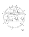
- the figure 2 schematically represents a cross section through the fuselage of the aircraft shown on the figure 1 at the second zone 12 of the first bridge. At this level, there is also the second bridge 22. In this example section, ten passengers can travel abreast and access Seating is done by three lanes arranged on two separate levels.
- the volume of this cargo is less than the volume of a bunker encountered on aircraft of the prior art equivalent dimensions.
- This bunker nevertheless makes it possible to receive containers 28.
- containers 28 are, for example standard LD3-45W type containers (whereas in a prior art aircraft it is planned to receive LD1 standard containers in the hold). , LD2, LD3 or LD6).
- the second zone 12 of the first bridge has a substantially plane floor.
- On this figure 2 it is proposed to have six front seats, these seats being served by two lanes 20.
- a configuration of type 1, 4, 1 has the advantage that each passenger can come to sit or can get up and move in the aircraft by having to apologize to a only maximum neighbor.
- the ceiling height being limited, it is proposed to have the floor of the corridor 20 at a level such that it allows for example a ceiling height of the order of 2.10 m .
- the corridor 20 is here in the middle position and is disposed above the storage space between the two double columns of seats 18 located in the second zone 12 of the first bridge.
- the fact that the floor of the corridor 20 of the second bridge 22 is disposed at a lower level and come to encroach on the space below the second bridge 22 does not harm the comfort of the passengers of the first bridge.
- the storage space can be used to have storage furniture acting as luggage chests for passengers traveling on the seats 18 of the double central columns. The height is sufficient, it can even be considered to create here changing rooms for hanging jackets and / or coats.
- each of the longitudinal zones extending on either side of the central corridor 20 is flat; in other words, the floor under each double column of seats 18 is flat, contrary to what is proposed in US2002 / 0033432 where each seating area has a complex floor whose level varies in the longitudinal direction.
- the lack of difference in levels along the longitudinal direction in the second bridge according to the invention in the seating areas allows the use of conventional seats, feet.
- the second bridge 22 is arranged at approximately 0.50 m above the ground level of the adjacent seating area 18.
- the second bridge 22 extends for example substantially to the seat height of the seats 18. As illustrated on the figure 2 this position makes it possible to provide under the second bridge the presence of luggage compartments 32 and on the second bridge 22, between the seats 18 and the fuselage 2, storage 34 for luggage.
- Shelves 36 may also be provided above the seats 18 of the second bridge 22 for for example, to receive clothing and / or small parcels.
- the figure 3 shows in side view a longer-haul aircraft fuselage larger than the aircraft represented on the figures 1 and 2 .
- a cockpit 4 and at the rear of this fuselage 2 a rear cone 6.
- a wing 8 more important than in the embodiment of figures 1 and 2 . Therefore, the second zone 12 as described above can not extend at the level of the wing 8. It is then proposed to have a second bridge 22 in front of the wing 8 and behind it. We find here in front of the wing and behind it each time a configuration quite similar to that described above.
- the first bridge then presents here two first zones 10: one located just behind the cockpit 4 and the other above the wing 8, at the rear of the latter. There are also two second zones 12, one in front of the wing 8 and the other behind it. Likewise, two third zones 14 are provided, one above the wing 8, in front of the latter, and the other in the vicinity of the rear cone 6. The third zone 14 and the first zone 10 being above the wing 8 are combined into an area subsequently called intermediate plate 38.
- the figure 4 illustrates the present invention by comparing a conventional configuration in a prior art aircraft (seven front passengers and two lanes on a bridge) with a variant of the proposed configuration on the figure 2 (ten front passengers and three lanes on two decks).
- an aircraft having a substantially cylindrical circular fuselage with a diameter of the order of 5 m.
- On the left of the figure 4 in a two-lane configuration there is in the center a set 40 of three columns of seats.
- a corridor 20 separates each time the assembly 40 of three columns of seats of a set 42 of two columns of seats.
- the aircraft can carry in its hold 26, below the single bridge, a pair of type LD2 containers.
- FIG. 4 schematically shows a fuselage section of an aircraft according to the present invention, said aircraft having a substantially cylindrical fuselage 2 having a circular diameter of 5 m.
- This configuration represents that described with reference to the figure 2 but illustrated more schematically and with a variant.
- the seats of the columns 44 are raised so as to have the passengers taking place on these seats at the fuselage where its width is the largest. In this way, the comfort of the passengers is improved.
- the floor of the second deck 22 has a shape adapted to allow sufficient room for the passengers sitting on the seats of the columns 44.
- the shape of this floor is adapted to optimize both the space at the first bridge and the second bridge.
- the Figures 5 and 6 present possible configurations for aircraft with a larger fuselage diameter.
- the figure 5 illustrates a configuration for a fuselage having for example a diameter of the order of 5.60 m.
- the diameter of the fuselage is for example 6.10 m.
- the two sets 42 lateral, located closest to the fuselage are raised relative to the two central sets 42.
- the floor of the first bridge can here be flat or be raised under the corresponding seats.
- the steps created in the second case do not exceed 0.60m in height. In this way, the two sets 42 side are closer to the maximum width area of the cabin and passengers benefit from more space.
- fuselage diameters there are sixteen front-row passengers on two decks with a fuselage diameter of 6.6 m or eleven, thirteen, fifteen, seventeen, or eighteen front-row variants on two decks with three or four corridors.
- the sets of columns of seats may comprise from one to six columns of seats.
- the shape of the floor of the second bridge adapts and can have many different levels (in the transverse direction) so as to optimize the space in the corridors 20, seats but also storage spaces for luggage (to each time both at the first bridge and the second).
- the figures 7 and 8 schematically illustrate in side view and in plan view a possible arrangement for an aircraft according to the present invention.
- a medium-type aircraft such as the one represented on the figures 1 and 2 .
- a long-haul aircraft such as the one shown on the figure 3 , we could have twice the same layout as the one shown on the figures 7 and 8 a similar arrangement being arranged in front of the wing and the other behind it.
- the figures 7 and 8 are provided to illustrate the arrangement at the rectilinear ramps 24, the arrangement at the second zone 12 and the second bridge 22 having been previously described.
- bunkers 26 In the lower part of the fuselage 2, there is shown on the figure 7 , in addition to the wing 8, or more precisely the connection thereof to the fuselage, bunkers 26 (a front bunker and a rear bunker) and also housing 50 for receiving landing gear.
- first door 16 and the rear door 21 At the cabin, there is the first door 16 and the rear door 21. In dashed lines, there is shown intermediate doors 52. The presence of such doors is necessary if the distance between the first door 16 and the rear door 21 is greater than 60 feet (approximately 18.29 m).
- a toilet 54 At the front of the aircraft, there can be provided, in a conventional manner, behind the cockpit 4, a toilet 54 and a space 56 for storing food and drinks and possibly preparing meals, such space 56 being usually called galley.
- the figure 7 allows to locate the location of the various elements described in the length of the aircraft and also in height.
- the figure 8 allows for it to locate the positioning of the elements described with respect to the length of the aircraft and in the width thereof.
- the figure 8 thus also illustrates a corridor 58 for access to the cockpit.
- the seating positions 60 Folding seats intended for commercial flight crew and used especially during the take-off and landing phases of the aircraft.
- the left side of the aircraft that is to say on the side by which passengers usually board and disembark, locations 62 arranged specifically to accommodate people with disabilities. moving in armchairs.
- These locations 62 can be equipped to perform a stowage of a wheelchair. This allows a disabled person to travel in his own wheelchair without having to be transferred from his chair to a seat when boarding (and seat to his chair during disembarkation).
- the ramps 24 can begin just behind the first gate 16 and the corresponding galleys 56, as well as the locations 62, can be at least partially at the same level (measured along the axis of roll of the aircraft) as the ramps 24.
- toilets 54 for the passengers.
- a toilet 54 is provided for the passengers traveling on the second zone 12 of the first bridge and others for the passengers traveling on the second bridge 22.
- These toilets 54 can be arranged with a height offset and an overlap as illustrated in particular on the figure 7 .
- the access to the toilet 54 can be made either from the second bridge 22 or the second zone 12, or from the corresponding ramps 24.
- locations 62 may be provided to accommodate persons with disabilities. It can also be provided at this place a space to receive galleys, storage spaces, a bar, ... or even cargo. Seats can also be arranged here. They have the advantage that the passengers on these seats have before them a significant free space (a lot of legroom). Such places could, for example, be allocated primarily to families with children.
- the figure 9 schematically illustrates an alternative embodiment of the invention.
- the representation here is a very schematic side view of a medium-haul aircraft.
- the wing 8 and various doors of the aircraft.
- it has been chosen to adapt to an existing aircraft structure in which all the doors are arranged at a single bridge.
- a configuration as described above is repeated.
- This is adapted as follows: the first zone 10 of the first bridge is provided between the first door 16 and a first intermediate door 52. Between this first intermediate door 52 and a second intermediate door 52, there is the second zone 12 of the first bridge and a second bridge 22 and the corresponding ramps 24. Between the second intermediate door 52 and the rear door 21 is the third zone 14 of the first bridge.
- the first zone 10 and the third zone 14 are here advantageously arranged to receive passengers and therefore have corresponding seats.
- the diameter of the fuselage and the seats chosen one can have a variable number of passengers in the different areas of the aircraft.
- Such a configuration requires the presence of four pairs of type A exits.
- the figure 10 is a view similar to the view of the figure 9 for a long-haul aircraft with a larger wing size.
- 110 passengers can be provided at each of the second decks 22 and 110 other passengers at each of the second zones 12. It is also planned to install at most 110 passengers on the intermediate plateau 38 with for example a fifth door (of type A) at this plateau. If not, as illustrated on the figure 10 space 38 can be used for servitudes. This results in a maximum number of passengers for such a configuration of 550 passengers (with five doors).
- figure 11 illustrates the wide variety of forms that can take floors especially at the second bridge 22. As indicated above, these floors are preferably made by molding a composite material based on carbon. The molded part has a profiled shape and the cross sections of this shaped shape are shown on the Figures 11A to 11G .
- the Figures 11A and 11F correspond to substantially planar bridges. We recognize for example on the Figure 11B the profiled section of the second bridge of the figure 2 .
- the figure 12 illustrates how a floor like those illustrated on the Figures 11A to 11G can take place in the aircraft.
- two frames 66 successive.
- the primary structure of an aircraft has annular frames connected by longitudinal members which thus form the "frame" of the aircraft on which the outer skin is fixed and which carries all the structures to the outside. inside the fuselage.
- the second zone 12 of the first bridge is for example mounted on the frames 66 in a conventional manner, for example using sleepers (not shown). It is proposed here to base the floor of the second bridge 22 on the first bridge as shown in FIG. figure 12 . For clarity, the floors corresponding to the first bridge and the second bridge are shown in dashed lines on this figure 12 .
- the floor of the second bridge 22 comes to rest on support brackets 68 which form intermediate parts between the first bridge and the second bridge.
- Each support bracket 68 has two branches 70 which each extend along a frame 66, being fixed thereto and resuming its shape so as to integrate the branches 70 to the structure of the aircraft.
- the free end of each branch 70 comes to rest on the floor corresponding to the second zone 12 of the first bridge and is fixed for example by means of a shoe-not shown.
- the two branches 70 are interconnected by a base 72 which forms the actual support of the floor of the second bridge 22.
- the base 72 extends longitudinally between two successive frames 66 and thus forms a bearing on which an edge of the floor of the second bridge 22 comes to rest.
- the floors of the second bridge are thus supported longitudinally.
- the transverse support is provided by the floor itself. This floor is made of sections extending for example each on two or three frames and each section is nested in the neighboring section so as to achieve a mutual transverse support.
- the figure 13 illustrates a complex shaped element, moldable in the same material as the floors of the second bridge 22 to realize a ramp 24 and an arrangement around it, comprising for example luggage racks 64.
- luggage racks 64 are provided on either side of a ramp 24. Dashed lines illustrate that it may be envisaged to have, for example, a staircase over a given width associated with a neighboring ramp.
- the opening of the luggage lockers 64 is here such that the luggage is introduced longitudinally (with respect to the direction of movement of the aircraft) in the bins.
- a lateral opening of the luggage racks 64 could be provided so as to provide a transverse introduction of the luggage therein.
- the upper face 74 of the lockers could then for example be used to receive a seat, or a storage space for coats, a display, ....
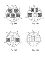
- FIGS. 14A to 14D illustrate fuselage sections of an aircraft capable of carrying fifteen front passengers on two levels with three access passages, or corridors 20, around the ramps 24 in an aircraft whose fuselage for example has a height of 6.1 m and a width of 6.0 m.
- the figure 14A corresponds to a cross section at the top of a ramp 24 or in a fuselage portion having a second bridge 22.
- first bridge three sets 40 of three columns of seats are distributed and two corridors 20 separate in pairs the 40.
- second deck two sets 40 of three columns of seats are separated by a corridor 20.
- storage spaces 76 can accommodate luggage of passengers traveling on the upper deck.
- the Figure 14B is a section made at a ramp 24, for example 1 m from the upper end of the ramp 24 allowing access to the second bridge 22.
- the fuselage of the aircraft is reduced slightly and it is planned to have only ten passengers in front.
- On the lower deck because of the ramp 24 it is no longer possible to comfortably accommodate passengers in the center of the fuselage.
- the space available under the ramp 24 is then used to achieve a storage chest 78 to accommodate including passenger luggage traveling in the second zone 12 of the first bridge.
- the lateral assemblies 40 of the lower deck are not impacted by the ramp and therefore still accommodate three passengers in front.
- the side storage space 76 can therefore be increased.
- the present invention allows, compared to a fuselage of the prior art, for the same diameter or equivalent section, on the same length, to accommodate a larger number of passengers without doing so at the expense of comfort thereof.
- the present invention also adapts to the structure of the aircraft (sails, position of the doors, etc.).
- the passengers for example in economy class, it is possible to provide seats having a width of the order of 0.5 m arranged in the longitudinal direction with a pitch of 0.8 m to 0.85 m with 1.50 m vertical margin.
- the corridors as for them have a width for example of 0.5 m and a height at least equal to 2 m.
- the complex shape including the second bridge ensures these various values for all seats and all corridors.
- each passenger can be guaranteed enough space to accommodate a standard wheeled suitcase, commonly known as a roller case, of 115 or 125 cm. Additional storage space is also provided. This also improves the comfort of passengers who can carry more luggage with them in the cabin and no longer have to drop them before boarding to register them in the hold. For small bags, handbags, clothing, etc., it is possible to provide solutions.
- the above description provides shelves 36 but also storage spaces 48.
- the luggage lockers 64 are provided for larger luggage, which can also possibly travel in the hold.
- the space at the level of the ramps is not a lost space.
- Large volumes available around the rectilinear ramps can be used, as indicated above, for toilets, the storage of trolleys and / or luggage. It could also be used to receive additional seats.
- the ground service is the same as for a single-bridge aircraft of the prior art. Passengers embark and disembark at the front left of the aircraft. If the aircraft is parked at an offshore station, stairs may be provided at the front and rear left of the aircraft. Access for police vehicles or cleaning, the loading of the bunkers are made to the right of the aircraft.
- the solution proposed by the present invention allows a much more efficient passenger flow than with a mono-bridge aircraft with two (or three) corridors. Indeed, at the level of the zones in which there are two bridges, the flow of passengers is optimized allowing a more fluid circulation of the passengers (more corridors available).
- the present invention allows, for a given number of passengers, to have a relatively short cabin. Such a structure -courte- allows for example to group the carriages at the front of the cabin and the toilet at the rear of it.
- the present invention also allows the reception of disabled passengers or unaccompanied children (commonly called UM) in good conditions and close to the flight crew.
- a privileged area may be provided for these travelers.
- the slope of the ramps is compatible with a safe ascent or descent of passengers, either in the normal boarding and unloading mode or during an evacuation of the aircraft.
- the concept proposed above is particularly suitable for aircraft with a short fuselage. It makes it possible to transport 250 passengers in an aircraft about 39 m long (corresponding to the length of an aircraft marketed under the A320 brand).
- the proposed innovative configuration makes it possible to make the aircraft compatible with the installations of the various current airports while minimizing the time of call and while limiting the surface of the parking station.
- the proposed concept can also be used for larger aircraft, as shown in the drawings with however still a concern for compactness.
Landscapes
- Engineering & Computer Science (AREA)
- Aviation & Aerospace Engineering (AREA)
- Mechanical Engineering (AREA)
- Body Structure For Vehicles (AREA)
- Escalators And Moving Walkways (AREA)
- Bridges Or Land Bridges (AREA)
- Vehicle Step Arrangements And Article Storage (AREA)
- Seats For Vehicles (AREA)
Applications Claiming Priority (1)
| Application Number | Priority Date | Filing Date | Title |
|---|---|---|---|
| FR1159454A FR2981634B1 (fr) | 2011-10-19 | 2011-10-19 | Cabine d'aeronef permettant d'accueillir des passagers sur plusieurs niveaux et aeronef correspondant |
Publications (2)
| Publication Number | Publication Date |
|---|---|
| EP2583894A2 true EP2583894A2 (de) | 2013-04-24 |
| EP2583894A3 EP2583894A3 (de) | 2017-11-15 |
Family
ID=47018095
Family Applications (1)
| Application Number | Title | Priority Date | Filing Date |
|---|---|---|---|
| EP12188948.9A Withdrawn EP2583894A3 (de) | 2011-10-19 | 2012-10-18 | Luftfahrzeugkabine, die die Aufnahme von Passagieren auf mehreren Ebenen erlaubt, und entsprechendes Luftfahrzeug |
Country Status (4)
| Country | Link |
|---|---|
| US (1) | US9278757B2 (de) |
| EP (1) | EP2583894A3 (de) |
| CN (1) | CN103057706B (de) |
| FR (1) | FR2981634B1 (de) |
Cited By (1)
| Publication number | Priority date | Publication date | Assignee | Title |
|---|---|---|---|---|
| WO2016162241A1 (en) * | 2015-04-10 | 2016-10-13 | Airbus Operations Gmbh | Passenger cabin area |
Families Citing this family (9)
| Publication number | Priority date | Publication date | Assignee | Title |
|---|---|---|---|---|
| US10589836B2 (en) | 2010-03-03 | 2020-03-17 | The Boeing Company | Split level forward double deck airliner |
| US9708065B2 (en) * | 2015-04-07 | 2017-07-18 | The Boeing Company | Crown cabin configuration for an aircraft |
| US10597161B2 (en) * | 2016-02-17 | 2020-03-24 | B/E Aerospace, Inc. | Space-optimizing seating arrangements for passenger transport and methods therefor |
| EP3263457B1 (de) * | 2016-06-30 | 2020-11-25 | The Boeing Company | Zweistöckiges flugzeug mit geteilten frontebenen |
| FR3066474B1 (fr) * | 2017-05-19 | 2021-06-25 | Zodiac Aerospace | Agencement modulaire destine a accueillir au moins un passager d'un avion et cabine d'avion comprenant au moins un tel agencement modulaire, notamment au niveau d'une zone cargo de l'avion |
| US11136137B2 (en) * | 2018-09-10 | 2021-10-05 | Rockwell Collins, Inc. | Non-intrusive passenger rest cabin monitoring system |
| DE102019102483A1 (de) * | 2019-01-31 | 2020-08-06 | Airbus Operations Gmbh | Passagierkabine für ein Fahrzeug sowie ein Fahrzeug mit mindestens einer derartigen Kabine |
| DE102019102476A1 (de) * | 2019-01-31 | 2020-08-06 | Airbus Operations Gmbh | Passagierkabine für ein Fahrzeug sowie ein Fahrzeug mit mindestens einer derartigen Kabine |
| US20250042548A1 (en) * | 2023-07-31 | 2025-02-06 | Young Seo CHO | Seat system for airplane |
Citations (7)
| Publication number | Priority date | Publication date | Assignee | Title |
|---|---|---|---|---|
| EP0514650A1 (de) | 1991-05-21 | 1992-11-25 | Deutsche Airbus GmbH | Luftfahrzeug mit Tragflügeln und einem Rumpf |
| EP0780335A2 (de) | 1995-12-22 | 1997-06-25 | DaimlerChrysler Aerospace Airbus Gesellschaft mit beschränkter Haftung | Vorrichtung zum Befördern von Personen oder Lasten in Mehrdeckflugzeugen |
| EP1164077A1 (de) | 2000-06-15 | 2001-12-19 | EADS Airbus GmbH | Passagierkabine eines Verkehrsflugzeuges |
| US20020033432A1 (en) | 2000-07-14 | 2002-03-21 | Mikosza Olgierd Stanislaw | Vehicle seating arrangement |
| EP1778540A1 (de) | 2004-07-26 | 2007-05-02 | Airbus | Anordnung des oberen teils einer flugzeugkabine |
| EP2460272A1 (de) | 2010-09-09 | 2012-06-06 | IDENT Technology AG | Sensorvorrichtung und verfahren zur zugriffs- und näherungserkennung |
| EP2460727A2 (de) | 2010-12-03 | 2012-06-06 | The Boeing Company | Flugzeugkonfiguration mit Rampenzugang auf mehrere Decks |
Family Cites Families (19)
| Publication number | Priority date | Publication date | Assignee | Title |
|---|---|---|---|---|
| US2281581A (en) * | 1940-03-28 | 1942-05-05 | Budd Edward G Mfg Co | Dining car |
| GB727159A (en) * | 1952-05-21 | 1955-03-30 | Blackburn & Gen Aircraft Ltd | Improvements in or relating to aircraft |
| US4055317A (en) * | 1976-06-30 | 1977-10-25 | The Boeing Company | Aft main deck split level galley |
| US4066227A (en) * | 1976-07-16 | 1978-01-03 | Buchsel Christian K E | Mezzanine structure for wide-bodied passenger aircraft |
| US5063859A (en) * | 1988-10-07 | 1991-11-12 | Rader Thomas G | Double-level railroad car having a flat center sill |
| US4925132A (en) * | 1988-11-30 | 1990-05-15 | The Beta Group | Wide-body aircraft having efficient utilization of interior space and method therefor |
| US5115999A (en) * | 1990-01-11 | 1992-05-26 | The Boeing Company | Aft double deck airplane |
| DE4416506C2 (de) * | 1994-05-10 | 1999-12-02 | Daimler Chrysler Aerospace | Passagierflugzeug |
| US6237872B1 (en) * | 1997-02-14 | 2001-05-29 | Reuven Bar-Levav | Aircraft cabin environment |
| US5992797A (en) * | 1998-09-18 | 1999-11-30 | The Boeing Company | Dual upper deck airplane |
| US6478253B1 (en) * | 2001-04-20 | 2002-11-12 | The Boeing Company | Airframe having area-ruled fuselage keel |
| US6616098B2 (en) * | 2001-08-13 | 2003-09-09 | The Boeing Company | Mid-level deck for passenger aircraft |
| US6705567B2 (en) * | 2002-05-06 | 2004-03-16 | The Boeing Company | Tandem wing aircraft and method for manufacturing and operating such aircraft |
| US6772977B2 (en) * | 2002-10-10 | 2004-08-10 | The Boeing Company | Aircraft with multipurpose lower decks and associated methods of manufacture |
| DE102004033068B4 (de) * | 2004-07-08 | 2008-09-25 | Airbus Deutschland Gmbh | Verkehrsflugzeug mit einem Hauptdeck und einem Unterdeck |
| US7536958B2 (en) * | 2006-05-09 | 2009-05-26 | Raul V. Bravo & Associates, Inc. | Passenger rail car |
| DE102007018326B4 (de) * | 2007-04-18 | 2010-05-06 | Airbus Deutschland Gmbh | Lagerung zur Befestigung von Treppen in einem Flugzeug |
| GB0708891D0 (en) * | 2007-05-09 | 2007-06-20 | Airbus Uk Ltd | Aircraft toilet facility |
| US9108719B2 (en) * | 2010-03-03 | 2015-08-18 | The Boeing Company | Aircraft with AFT split-level multi-deck fusealge |
-
2011
- 2011-10-19 FR FR1159454A patent/FR2981634B1/fr not_active Expired - Fee Related
-
2012
- 2012-10-18 EP EP12188948.9A patent/EP2583894A3/de not_active Withdrawn
- 2012-10-19 CN CN201210597065.XA patent/CN103057706B/zh not_active Expired - Fee Related
- 2012-10-19 US US13/655,843 patent/US9278757B2/en not_active Expired - Fee Related
Patent Citations (9)
| Publication number | Priority date | Publication date | Assignee | Title |
|---|---|---|---|---|
| EP0514650A1 (de) | 1991-05-21 | 1992-11-25 | Deutsche Airbus GmbH | Luftfahrzeug mit Tragflügeln und einem Rumpf |
| EP0780335A2 (de) | 1995-12-22 | 1997-06-25 | DaimlerChrysler Aerospace Airbus Gesellschaft mit beschränkter Haftung | Vorrichtung zum Befördern von Personen oder Lasten in Mehrdeckflugzeugen |
| EP1164077A1 (de) | 2000-06-15 | 2001-12-19 | EADS Airbus GmbH | Passagierkabine eines Verkehrsflugzeuges |
| US6547184B2 (en) | 2000-06-15 | 2003-04-15 | Airbus Deutschland Gmbh | Modular trim paneling and outfitting system for an aircraft passenger cabin interior |
| US20020033432A1 (en) | 2000-07-14 | 2002-03-21 | Mikosza Olgierd Stanislaw | Vehicle seating arrangement |
| EP1778540A1 (de) | 2004-07-26 | 2007-05-02 | Airbus | Anordnung des oberen teils einer flugzeugkabine |
| US7290735B2 (en) | 2004-07-26 | 2007-11-06 | Airbus | Layout of the top part of an aircraft cabin |
| EP2460272A1 (de) | 2010-09-09 | 2012-06-06 | IDENT Technology AG | Sensorvorrichtung und verfahren zur zugriffs- und näherungserkennung |
| EP2460727A2 (de) | 2010-12-03 | 2012-06-06 | The Boeing Company | Flugzeugkonfiguration mit Rampenzugang auf mehrere Decks |
Cited By (2)
| Publication number | Priority date | Publication date | Assignee | Title |
|---|---|---|---|---|
| WO2016162241A1 (en) * | 2015-04-10 | 2016-10-13 | Airbus Operations Gmbh | Passenger cabin area |
| US10202195B2 (en) | 2015-04-10 | 2019-02-12 | Airbus Operations Gmbh | Passenger cabin area |
Also Published As
| Publication number | Publication date |
|---|---|
| FR2981634B1 (fr) | 2014-10-24 |
| CN103057706A (zh) | 2013-04-24 |
| EP2583894A3 (de) | 2017-11-15 |
| CN103057706B (zh) | 2017-05-03 |
| US20130119203A1 (en) | 2013-05-16 |
| US9278757B2 (en) | 2016-03-08 |
| FR2981634A1 (fr) | 2013-04-26 |
Similar Documents
| Publication | Publication Date | Title |
|---|---|---|
| FR2981634A1 (fr) | Cabine d'aeronef permettant d'accueillir des passagers sur plusieurs niveaux et aeronef correspondant | |
| EP2094563B1 (de) | Vorderteil für ein flugzeug mit einem ruhebereich für mindestens einen piloten | |
| EP2219945B1 (de) | Optimiertes flugzeugkabinenlayout | |
| US7367528B2 (en) | Airport system for operations, safety, and security | |
| US4097008A (en) | Cargo handling system for aircraft | |
| EP2051905B1 (de) | Heckkonus für flugzeug | |
| EP0408432A1 (de) | Flugzeugrumpf mit grossem Fassungsvermögen | |
| EP1778540B1 (de) | Anordnung des oberen teils einer flugzeugkabine | |
| CA2479251C (fr) | Avion a trois fuselages et familles d'avions de ce type | |
| FR2929244A1 (fr) | Espace de travail et de rangement a l'arriere d'une cabine d'aeronef | |
| WO2004009442A1 (fr) | Module de cabine d’aeronef pour passagers | |
| FR2916735A1 (fr) | Escalier pour aeronef | |
| US20080217475A1 (en) | Airport system for safety and security | |
| EP2743182B1 (de) | Möbelstück für Luftfahrzeug, das Verteilungsmittel eines Transportwagens zwischen zwei Bereichen umfasst | |
| US20080149766A1 (en) | Rest compartment for an aircraft pilot | |
| US20070267544A1 (en) | Aircraft with improved cargo hold | |
| US10589836B2 (en) | Split level forward double deck airliner | |
| FR2903664A1 (fr) | Amenagement de cabine d'aeronef presentant des couchettes dans la partie superieure de la cabine. | |
| FR3064596A1 (fr) | Train d'atterrissage avant de hauteur reduite et aeronef, en particulier aile volante, equipe d'un tel train avant | |
| US9452817B1 (en) | Aircraft having split level cabin floors | |
| FR3082815A1 (fr) | Voiture a terrasse | |
| FR2873349A1 (fr) | Amenagement de la partie superieure de la cabine d'un aeronef | |
| EP3623277B1 (de) | Frontbereich eines luftfahrzeugs mit einer vereinfachten struktur | |
| EP3263457B1 (de) | Zweistöckiges flugzeug mit geteilten frontebenen | |
| FR3073207A1 (fr) | Moyen de transport ainsi que systeme et procede de transport de bagages dans un moyen de transport |
Legal Events
| Date | Code | Title | Description |
|---|---|---|---|
| PUAI | Public reference made under article 153(3) epc to a published international application that has entered the european phase |
Free format text: ORIGINAL CODE: 0009012 |
|
| AK | Designated contracting states |
Kind code of ref document: A2 Designated state(s): AL AT BE BG CH CY CZ DE DK EE ES FI FR GB GR HR HU IE IS IT LI LT LU LV MC MK MT NL NO PL PT RO RS SE SI SK SM TR |
|
| AX | Request for extension of the european patent |
Extension state: BA ME |
|
| PUAL | Search report despatched |
Free format text: ORIGINAL CODE: 0009013 |
|
| AK | Designated contracting states |
Kind code of ref document: A3 Designated state(s): AL AT BE BG CH CY CZ DE DK EE ES FI FR GB GR HR HU IE IS IT LI LT LU LV MC MK MT NL NO PL PT RO RS SE SI SK SM TR |
|
| AX | Request for extension of the european patent |
Extension state: BA ME |
|
| RIC1 | Information provided on ipc code assigned before grant |
Ipc: B64C 1/18 20060101AFI20171010BHEP Ipc: B64D 11/00 20060101ALI20171010BHEP |
|
| STAA | Information on the status of an ep patent application or granted ep patent |
Free format text: STATUS: REQUEST FOR EXAMINATION WAS MADE |
|
| 17P | Request for examination filed |
Effective date: 20180416 |
|
| RBV | Designated contracting states (corrected) |
Designated state(s): AL AT BE BG CH CY CZ DE DK EE ES FI FR GB GR HR HU IE IS IT LI LT LU LV MC MK MT NL NO PL PT RO RS SE SI SK SM TR |
|
| STAA | Information on the status of an ep patent application or granted ep patent |
Free format text: STATUS: EXAMINATION IS IN PROGRESS |
|
| 17Q | First examination report despatched |
Effective date: 20191024 |
|
| GRAP | Despatch of communication of intention to grant a patent |
Free format text: ORIGINAL CODE: EPIDOSNIGR1 |
|
| STAA | Information on the status of an ep patent application or granted ep patent |
Free format text: STATUS: GRANT OF PATENT IS INTENDED |
|
| INTG | Intention to grant announced |
Effective date: 20200602 |
|
| STAA | Information on the status of an ep patent application or granted ep patent |
Free format text: STATUS: THE APPLICATION IS DEEMED TO BE WITHDRAWN |
|
| 18D | Application deemed to be withdrawn |
Effective date: 20201013 |