EP2584101A1 - Machine de construction électrique - Google Patents
Machine de construction électrique Download PDFInfo
- Publication number
- EP2584101A1 EP2584101A1 EP11795594.8A EP11795594A EP2584101A1 EP 2584101 A1 EP2584101 A1 EP 2584101A1 EP 11795594 A EP11795594 A EP 11795594A EP 2584101 A1 EP2584101 A1 EP 2584101A1
- Authority
- EP
- European Patent Office
- Prior art keywords
- battery
- frame
- vehicle
- rear part
- base frame
- Prior art date
- Legal status (The legal status is an assumption and is not a legal conclusion. Google has not performed a legal analysis and makes no representation as to the accuracy of the status listed.)
- Granted
Links
Images








Classifications
-
- E—FIXED CONSTRUCTIONS
- E02—HYDRAULIC ENGINEERING; FOUNDATIONS; SOIL SHIFTING
- E02F—DREDGING; SOIL-SHIFTING
- E02F9/00—Component parts of dredgers or soil-shifting machines, not restricted to one of the kinds covered by groups E02F3/00 - E02F7/00
-
- E—FIXED CONSTRUCTIONS
- E02—HYDRAULIC ENGINEERING; FOUNDATIONS; SOIL SHIFTING
- E02F—DREDGING; SOIL-SHIFTING
- E02F9/00—Component parts of dredgers or soil-shifting machines, not restricted to one of the kinds covered by groups E02F3/00 - E02F7/00
- E02F9/08—Superstructures; Supports for superstructures
- E02F9/0858—Arrangement of component parts installed on superstructures not otherwise provided for, e.g. electric components, fenders, air-conditioning units
-
- B—PERFORMING OPERATIONS; TRANSPORTING
- B60—VEHICLES IN GENERAL
- B60K—ARRANGEMENT OR MOUNTING OF PROPULSION UNITS OR OF TRANSMISSIONS IN VEHICLES; ARRANGEMENT OR MOUNTING OF PLURAL DIVERSE PRIME-MOVERS IN VEHICLES; AUXILIARY DRIVES FOR VEHICLES; INSTRUMENTATION OR DASHBOARDS FOR VEHICLES; ARRANGEMENTS IN CONNECTION WITH COOLING, AIR INTAKE, GAS EXHAUST OR FUEL SUPPLY OF PROPULSION UNITS IN VEHICLES
- B60K1/00—Arrangement or mounting of electrical propulsion units
- B60K1/04—Arrangement or mounting of electrical propulsion units of the electric storage means for propulsion
-
- E—FIXED CONSTRUCTIONS
- E02—HYDRAULIC ENGINEERING; FOUNDATIONS; SOIL SHIFTING
- E02F—DREDGING; SOIL-SHIFTING
- E02F9/00—Component parts of dredgers or soil-shifting machines, not restricted to one of the kinds covered by groups E02F3/00 - E02F7/00
- E02F9/08—Superstructures; Supports for superstructures
-
- E—FIXED CONSTRUCTIONS
- E02—HYDRAULIC ENGINEERING; FOUNDATIONS; SOIL SHIFTING
- E02F—DREDGING; SOIL-SHIFTING
- E02F9/00—Component parts of dredgers or soil-shifting machines, not restricted to one of the kinds covered by groups E02F3/00 - E02F7/00
- E02F9/08—Superstructures; Supports for superstructures
- E02F9/0808—Improving mounting or assembling, e.g. frame elements, disposition of all the components on the superstructures
-
- E—FIXED CONSTRUCTIONS
- E02—HYDRAULIC ENGINEERING; FOUNDATIONS; SOIL SHIFTING
- E02F—DREDGING; SOIL-SHIFTING
- E02F9/00—Component parts of dredgers or soil-shifting machines, not restricted to one of the kinds covered by groups E02F3/00 - E02F7/00
- E02F9/20—Drives; Control devices
- E02F9/2058—Electric or electro-mechanical or mechanical control devices of vehicle sub-units
- E02F9/2062—Control of propulsion units
- E02F9/207—Control of propulsion units of the type electric propulsion units, e.g. electric motors or generators
-
- E—FIXED CONSTRUCTIONS
- E02—HYDRAULIC ENGINEERING; FOUNDATIONS; SOIL SHIFTING
- E02F—DREDGING; SOIL-SHIFTING
- E02F9/00—Component parts of dredgers or soil-shifting machines, not restricted to one of the kinds covered by groups E02F3/00 - E02F7/00
- E02F9/20—Drives; Control devices
- E02F9/22—Hydraulic or pneumatic drives
- E02F9/226—Safety arrangements, e.g. hydraulic driven fans, preventing cavitation, leakage, overheating
-
- B—PERFORMING OPERATIONS; TRANSPORTING
- B60—VEHICLES IN GENERAL
- B60K—ARRANGEMENT OR MOUNTING OF PROPULSION UNITS OR OF TRANSMISSIONS IN VEHICLES; ARRANGEMENT OR MOUNTING OF PLURAL DIVERSE PRIME-MOVERS IN VEHICLES; AUXILIARY DRIVES FOR VEHICLES; INSTRUMENTATION OR DASHBOARDS FOR VEHICLES; ARRANGEMENTS IN CONNECTION WITH COOLING, AIR INTAKE, GAS EXHAUST OR FUEL SUPPLY OF PROPULSION UNITS IN VEHICLES
- B60K1/00—Arrangement or mounting of electrical propulsion units
- B60K1/04—Arrangement or mounting of electrical propulsion units of the electric storage means for propulsion
- B60K2001/0405—Arrangement or mounting of electrical propulsion units of the electric storage means for propulsion characterised by their position
- B60K2001/0416—Arrangement in the rear part of the vehicle
-
- B—PERFORMING OPERATIONS; TRANSPORTING
- B60—VEHICLES IN GENERAL
- B60K—ARRANGEMENT OR MOUNTING OF PROPULSION UNITS OR OF TRANSMISSIONS IN VEHICLES; ARRANGEMENT OR MOUNTING OF PLURAL DIVERSE PRIME-MOVERS IN VEHICLES; AUXILIARY DRIVES FOR VEHICLES; INSTRUMENTATION OR DASHBOARDS FOR VEHICLES; ARRANGEMENTS IN CONNECTION WITH COOLING, AIR INTAKE, GAS EXHAUST OR FUEL SUPPLY OF PROPULSION UNITS IN VEHICLES
- B60K1/00—Arrangement or mounting of electrical propulsion units
- B60K1/04—Arrangement or mounting of electrical propulsion units of the electric storage means for propulsion
- B60K2001/0455—Removal or replacement of the energy storages
- B60K2001/0477—Removal or replacement of the energy storages from the back
-
- B—PERFORMING OPERATIONS; TRANSPORTING
- B60—VEHICLES IN GENERAL
- B60Y—INDEXING SCHEME RELATING TO ASPECTS CROSS-CUTTING VEHICLE TECHNOLOGY
- B60Y2200/00—Type of vehicle
- B60Y2200/40—Special vehicles
- B60Y2200/41—Construction vehicles, e.g. graders, excavators
- B60Y2200/412—Excavators
Definitions
- the present invention relates to an electric construction machine such as hydraulic shovel, wheel loader, etc., which has an electric motor as a source of power and is operable with a battery device and a commercial power supply.
- Construction machines such as hydraulic shovels used for excavation work and demolition work are generally configured to supply the hydraulic fluid for the operation (hydraulic operating fluid) to hydraulic actuators such as a hydraulic motor for the traveling, a hydraulic motor for swinging, various hydraulic cylinders constituting a work implement, etc. by driving a hydraulic pump with a diesel engine.
- hydraulic actuators such as a hydraulic motor for the traveling, a hydraulic motor for swinging, various hydraulic cylinders constituting a work implement, etc. by driving a hydraulic pump with a diesel engine.
- the cab seat is arranged on the left side of the upper swing structure with respect to the transverse direction of the upper swing structure.
- the hydraulic pump, the electric motor, an oil tank, a heat exchanger (oil cooler), etc. are arranged on the right side of the cab seat.
- the battery device is arranged to the rear of the cab seat.
- the hydraulic pump, the electric motor, the oil tank, the heat exchanger, the battery device, etc. are stored in a single storage space formed by a cover.
- the hydraulic pump, the electric motor, the oil tank, the heat exchanger, etc. are cooled down by a cooling air flow which is circulated inside the storage space by a cooling fan.
- the battery device needs periodical maintenance by a serviceperson. Also for the maintenance of the battery device, the exterior cover of the hydraulic shovel has to be removed or the battery device has to be detached from the hydraulic shovel for checking the battery device. In the case of checking the battery device without detaching it from the construction machine, however, performing the check properly and efficiently is impossible since the battery device has been installed in a small space. The detaching of the battery device at the worksite also takes a considerably long time similarly to the replacement of the battery device, which seriously deteriorates the working efficiency.
- the battery technology is progressing remarkably these days.
- the lithium-ion batteries have high charging capacities and their capacities are expected to increase more and more in years to come. Therefore, it is desirable that the electric construction machines be designed to allow for replacement of the batteries with different types of batteries according to the progress of the battery technology.
- the present invention provides an electric construction machine having a battery device mounted on a rear part of a vehicle body thereof, the electric construction machine performing operations by driving an electric motor with the battery device
- the vehicle body is made up of a vehicle main body and a vehicle rear part
- the vehicle main body includes a vehicle body frame to whose front a work implement is attached and a cab seat and a machine room, the cab seat and the machine room being provided on the vehicle body frame
- the vehicle body frame includes a main frame to whose front the work implement is attached, wherein the main frame has an overhanging part overhanging and extending in a longitudinal direction to reach the underside of the vehicle rear part
- the vehicle rear part includes a rear frame to be mounted on the overhanging part and a rear cover covering the rear frame, the rear cover forming therein a battery room in which the battery device is arranged and having a shape imitating a counter weight, and wherein the rear frame mounted on the overhanging part is fixed on the overhang
- the capacity (storable amount of electricity) of the battery device is limited and with the present performance of batteries, it is difficult even for a small-sized construction machine (e.g., small hydraulic shovel (so-called mini-shovel)) to continue the operation for an entire day with no replacement of the battery device unless the battery device is used together with the commercial power supply.
- a small-sized construction machine e.g., small hydraulic shovel (so-called mini-shovel)
- the vehicle body is made up of the vehicle main body and the vehicle rear part.
- the electric construction machine is configured so that the vehicle rear part is detachable from the vehicle main body by removing the bolt. Therefore, the replacement of the vehicle rear part is facilitated. Even when the electric construction machine is used for operations for a long time at a place where no commercial power supply is available, it is possible to replace the battery device easily and quickly and to increase the working efficiency by preparing another vehicle rear part loaded with a recharged battery device, detaching the already-attached vehicle rear part from the vehicle main body when the electricity amount of the battery device on the vehicle rear part has become insufficient, and attaching the prepared vehicle rear part that is loaded with the recharged battery device, to the vehicle main body.
- the maintenance of the battery device can also be done with ease, by replacing the vehicle rear part with another vehicle rear part loaded with a recharged battery device and moving the detached vehicle rear part to maintenance facilities.
- the new battery device when a different type of battery device having an increased capacity has appeared due to the progress of the battery technology and the new battery device is desired to be mounted to the an electric construction machine, it is possible to detach the vehicle rear part loaded with the currently used battery device from the vehicle main body and attach another vehicle rear part loaded with the different type of battery device to the vehicle main body. Consequently, the battery device can easily be replaced with different types of battery devices according to the progress of the battery technology.
- the rear frame of the vehicle rear part can be formed in various shapes differing in the length in the longitudinal direction, by which the number of the mounted batteries can be changed and adjusted to suit the operating time required of the electric construction machine.
- the battery room is formed inside the rear cover, the battery device can be protected from shocks from the outside during the swing of the vehicle body.
- the vehicle rear part in a shape imitating the counter weight, an external appearance having innovativeness can be given to the electric construction machine.
- the overhanging part of the main frame of the vehicle main body includes two longitudinal ribs overhanging and extending in parallel in the longitudinal direction to reach the underside of the rear frame of the vehicle rear part.
- the rear frame of the vehicle rear part includes a base frame which couples with the two longitudinal ribs of the main frame from above.
- the base frame mounted on the two longitudinal ribs of the main frame is fixed on the two longitudinal ribs using the bolt.
- fixing means for fixing the base frame on the two longitudinal ribs of the main frame includes not only the bolt but also two positioning pins provided corresponding to the two longitudinal ribs of the main frame.
- the base frame mounted on the two longitudinal ribs of the main frame is fixed on the two longitudinal ribs and prevented from coming off using the two positioning pins and the bolt, the base frame being detachable from the two longitudinal ribs by removing the positioning pins and the bolt.
- the whole of the vehicle rear part can be attached to and detached from the vehicle main body with ease while leaving the battery device mounted on the vehicle rear part.
- the base frame includes two side plates to be arranged inside the two longitudinal ribs, a base plate connecting lower ends of the two side plates, and outward horizontal flanges provided at upper ends of the two side plates, respectively.
- the base frame is mounted on the two longitudinal ribs by making the horizontal flanges be supported on upper ends of the two longitudinal ribs.
- the movement of the rear frame in the transverse direction is restricted by the two side plates of the base frame and the two longitudinal ribs of the main frame, and the movement of the rear frame in the vertical direction is restricted by the horizontal flanges of the base frame and the two longitudinal ribs of the main frame. Consequently, the vehicle rear part can be fixed to the vehicle main body more stably.
- the base frame has a support part to be used for setting the vehicle rear part on forks of a forklift.
- the support part is provided on the lower surface of the base frame and between the two longitudinal ribs of the main frame.
- the vehicle rear part is movable with respect to the vehicle main body using the forklift.
- the vehicle rear part can be replaced safely by use of a forklift even when the vehicle rear part loaded with the battery device is heavy.
- the vehicle rear part further includes at least one rear post erected on a rear part of the base frame and a battery storage structure attached on the base frame with bolts and storing the battery device.
- the rear post and the battery storage structure are equipped with wire attaching parts.
- the vehicle rear part is movable with respect to the vehicle main body by using a crane by attaching wires for the crane to the wire attaching parts.
- the vehicle rear part can be replaced safely by use of a crane even when the vehicle rear part loaded with the battery storage structure is heavy.
- the base frame has a plurality of mount rubbers attached thereon at prescribed intervals in the longitudinal direction.
- the vehicle rear part further includes a battery storage structure attached on the base frame with bolts via the mount rubbers and storing the battery device.
- the battery storage structure has a plurality of wire attaching parts.
- the battery storage structure is movable in the vertical direction with respect to the base frame by using a crane by attaching wires for the crane to the wire attaching parts.
- the battery storage structure can be replaced safely by use of a crane even when the battery storage structure loaded with the battery device is heavy.
- the vehicle rear part further includes a battery storage structure attached on the base frame and storing the battery device.
- the battery storage structure includes a battery table mount mounted on the base frame and multiple stages of battery tables mounted on the battery table mount.
- a battery table as the lowermost one of the multiple stages of battery tables is fixed on the battery table mount using bolts.
- the multiple stages of battery tables are supported to be separated from each other in the vertical direction via posts and are integrated by fixing upper and lower ends of each of the posts to corresponding battery tables with bolts.
- the vehicle main body includes the cab seat provided on the vehicle body frame and a machine room in which a plurality of devices including the electric motor and an inverter for controlling the electric motor are arranged.
- the rear cover included in the vehicle rear part and having the shape imitating the counter weight covers a rear part, a right-hand part, a left-hand part and a top part of the vehicle rear part.
- the machine room is separated from the other parts of the vehicle main body by a partition plate.
- the battery room formed by the rear cover secures a space insulated from heat sources in the machine room by the partition plate. The space prevents effects of heat on batteries of the battery device arranged in the battery room.
- the replacement of the battery device can be conducted easily and quickly and the working efficiency can be increased.
- the battery device can be replaced easily and quickly, the maintenance of the battery device can be done with ease.
- the battery device can be replaced by detaching the whole of the vehicle rear part from the vehicle main body, the battery device can easily be replaced with different types of battery devices according to the progress of the battery technology.
- the rear frame of the vehicle rear part can be formed in various shapes differing in the length in the longitudinal direction, by which the number of the mounted batteries can be changed and adjusted to suit the operating time required of the electric construction machine.
- the battery room is formed inside the rear cover, the battery device can be protected from shocks from the outside during the swing of the vehicle body.
- the vehicle rear part in a shape imitating the counter weight, an external appearance having innovativeness can be given to the electric construction machine.
- Fig. 1 is a perspective view showing the external appearance of an electric hydraulic shovel in accordance with this embodiment.
- the reference character 1 in Fig. 1 represents the electric hydraulic shovel.
- the hydraulic shovel 1 comprises a lower travel structure 2 of the crawler type capable of traveling by itself, an upper swing structure 3 mounted on the lower travel structure 2 to be capable of swinging, and a work implement 4 of the swinging type attached to the front part of the upper swing structure 3 for performing earth/sand excavation, etc.
- the vehicle body of the hydraulic shovel 1 is formed by the upper swing structure 3 and the lower travel structure 2.
- the work implement 4 is made up of a boom 4A, an arm 4B, a bucket 4C, a boom cylinder 4D, an arm cylinder 4E, a bucket cylinder 4F, etc.
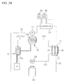
- Fig. 24 is a schematic diagram showing a driving/cooling system of the hydraulic shovel 1.
- the hydraulic shovel 1 comprises a hydraulic pump 17, an electric motor 18 as a source of power, an inverter 19, an oil tank 20, a heat exchanger 21 including an oil cooler 22 and a radiator 23, a control valve 24, a hydraulic fluid supply line 25, a hydraulic fluid discharge line 26, a coolant line 27 (27A, 27B, 27C), a coolant pump 28, a cooling fan 30, a battery device 31, etc.
- the electric motor 18 is powered by the battery device 31 as a power source and controlled by the inverter 19.
- the inverter 19 is controlled via unshown operating means and controller.
- the electric motor 19 is connected to the hydraulic pump 17. Being driven by the electric motor 18, the hydraulic pump 17 pumps up the hydraulic fluid from the oil tank 20 via the hydraulic fluid supply line 25 and drives hydraulic actuators such as the boom cylinder 4D, the arm cylinder 4E, the bucket cylinder 4F, a travel hydraulic motor (unshown) and a swing hydraulic motor (unshown) by supplying the hydraulic fluid to the actuators via the control valve 24.
- the hydraulic fluid returning from each actuator flows back to the oil tank 20 via the control valve 24 and the hydraulic fluid discharge line 26.
- the hydraulic fluid discharge line 26 is equipped with the oil cooler 22.
- the oil cooler 22 cools down the hydraulic fluid heated by the hydraulic devices by use of cooling air from the cooling fan 30.
- the electric motor 18 and the inverter 19 have cooling jackets 18A and 19A, respectively.
- a circulatory path for circulating the coolant through the radiator 23, the coolant line 27 (27a, 27B, 27C), the coolant pump 28 and the cooling jackets 18A and 19A is formed.
- the radiator 23 cools down the coolant heated by the electric motor 18 and the inverter 19 by use of cooling air from the cooling fan 30.
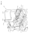
- Figs. 2 and 3 are schematic diagrams showing a state in which the upper swing structure 3 of the hydraulic shovel 1 has been separated into a vehicle main body and a vehicle rear part.
- the upper swing structure 3 in the separated state is viewed from its right side in Fig. 2 and from its left side in Fig. 3 .
- terms indicating directions mean directions from the viewpoint of the operator seated on the cab seat.
- the upper swing structure (vehicle body) 3 is made up of a vehicle main body 100 and a vehicle rear part 200.
- the vehicle main body 100 includes a swing frame (vehicle frame) 101 to whose front the work implement 4 is attached, and a cab seat 102 (generic name for equipment on which the operator is seated to operate the construction machine) and a machine room 103 which are mounted on the swing frame 101.
- the cab seat 102 is arranged in a left-hand part of the vehicle main body 100.
- the machine room 103 is arranged in a right-hand part of the vehicle main body 100 and on the right side of the cab seat 102.
- the cab seat 102 is of the canopy type, which is equipped with a canopy 104.
- the cab seat 102 has a floor panel 102a (see Fig. 1 ), on which devices/equipment necessary for letting the operator operate the hydraulic shovel 1 are mounted.
- the devices/equipment include a seat 105 on which the operator is seated, control levers 106a, 106b and 107, etc.
- the cab seat 102 may also be of the cabin type surrounded with panels and window panes.
- the machine room 103 stores the hydraulic pump 17, the electric motor 18, the inverter 19, the oil tank 20, the heat exchanger 21 (the oil cooler 22 and the radiator 23), the cooling fan 30, etc.
- the exterior cover 110 is made up of a left cover 110a covering a left rear part of the cab seat 102, a rear cover 110b covering a rear part of the cab seat 102, a floor cover 110c covering a lower front part and a side part of the floor panel 102 of the cab seat 102, and an upper right cover 110d and a right side cover 110e which are arranged on the right side of the cab seat 102 and covering the machine room 103.
- the vehicle rear part 200 includes a rear frame 201, a battery storage structure 203 and a rear cover 205.
- the rear frame 201 is connected to the swing frame 101 of the vehicle main body 100.
- the battery storage structure 203 storing the battery device 31 is mounted on the rear frame 201.
- the rear cover 205 covers the rear frame 201 and the battery storage structure 203 and forms a battery room 204 thereinside together with the left cover 110a and the rear cover 110b of the vehicle main body 100, etc.
- the rear cover 205 has a shape imitating the counter weight of the conventional engine-driven hydraulic shovels.
- the vehicle rear part 200 serves also as the counter weight that is generally employed for hydraulic shovels, by use of the weight of the battery storage structure 203, the rear frame 201 and the rear cover 205.
- the battery device 31 stored in the battery storage structure 203 is formed by electrically connecting a lot of battery modules 202 (see Fig. 6 ). As shown in Fig. 24 , the battery device 31 is electrically connected to the electric motor 18 installed in the machine room 103 and functions as a power supply for driving the electric motor 18. The electric motor 18 can also be driven by the commercial power supply.
- Fig. 4 is a perspective view magnifying the swing frame 101 of the vehicle main body 100.
- the swing frame 101 of the vehicle main body 100 is provided as a vehicle body frame to serve as the base of the upper swing structure 3. As shown in Fig. 4 , the swing frame 101 includes a main frame 120, a left side frame 130 and a right side frame 140.
- the main frame 120 includes a support bracket 121, longitudinal ribs 122a, 122b, 123a and 123b, a base plate 124, and a transverse plate 125.
- the work implement 4 is attached to the support bracket 121 provided at the front of the main frame 120.
- the left and right longitudinal ribs 122a and 122b are provided in a rear part of the main frame 120 to overhang and extend in parallel in the longitudinal direction to reach the underside of the vehicle rear part 200.
- the longitudinal ribs 123a and 123b are arranged in a front part of the main frame 120 to link the support bracket 121 with the longitudinal ribs 122a and 122b.
- the base plate 124 is a flat plate-like member attached to the lower ends of the longitudinal ribs 122a, 122b, 123a and 123b.
- the transverse plate 125 is erected on the base plate 124 to be sandwiched between the front longitudinal ribs (123a, 123b) and the rear longitudinal ribs (122a, 122b) and to extend across the longitudinal ribs.
- the two longitudinal ribs 122a and 122b form an overhanging part 122.
- a left part 125a of the transverse plate 125 protrudes and extends to the left side frame 130.
- the left side frame 130 includes a left overhang beam 131 overhanging leftward from the front end of the left front longitudinal rib 123a, a left overhang beam 132 overhanging leftward from a central part of the left rear longitudinal rib 122a, and a left frame member 133 connected to the left ends of the left overhang beams 131 and 132 and the left part 125a of the transverse plate 125.
- the right side frame 140 includes a right overhang beam 141, in a central part thereof, overhanging rightward from between the right front longitudinal rib 123b and the right rear longitudinal rib 122b, a right overhang beam 142, in a rear part thereof, overhanging rightward from a central part of the right rear longitudinal rib 122b, a right frame member 143 connected to the right ends of the right overhang beam 141 in the central part and the right overhang beam 142 in the rear part, a connection plate member 144 connecting the right front longitudinal rib 123b to the front end of the right frame member 143, and a heat exchanger support table 145 fixed to cross-link the connection plate member 144 with the right overhang beam 141 in the central part.
- the floor panel 102a (see Fig. 1 ) of the cab seat 102 is attached on the front longitudinal ribs 123a and 123b, the transverse plate 125 and the left front overhang beam 131 of the main frame 120.
- the cab seat 102 is mounted on the floor panel 102a.
- Partition plates 151 and 152 joined with each other in an L-shape are attached to upper ends of the front and rear right longitudinal ribs 123b and 122b and the right rear overhang beam 142 of the main frame 120.
- the machine room 103 is separated from the cab including the cab seat 102 and from the vehicle rear part 200 (especially, the battery room 204) by the partition plates 151 and 152.
- Multiple stages of support tables are provided on the right overhang beams 141 and 142 in the central and rear parts.
- the electric motor 18, the inverter 19, the hydraulic pump 17, etc. shown in Fig. 24 are set on the support tables.
- the oil tank 20 is set on the connection plate member 144.
- the heat exchanger 21 and the cooling fan 30 are set on the heat exchanger support table 145.
- the aforementioned left cover 110a and floor cover 110c are attached to the left frame member 133, the front face of the left overhang beam 131 of the left side frame 130, the left end of the left part 125a of the transverse plate 125 and the left end of the left overhang beam 132.
- the aforementioned right side cover 110e covering the machine room 103 is attached to the right frame member 143 and the right ends of the right overhang beams 141 and 142 of the right side frame 140.
- Pin holes 155a and 155b are formed through lateral surfaces of rear end parts of the rear longitudinal ribs 122a and 122b of the main frame 120.
- a hole 156 into which a bolt 302 (see Fig. 5 , etc.) is inserted, is formed through the lateral surface of the rear end part of the right rear longitudinal rib 122b to adjoin the pin hole 155b.
- Reinforcing plates 157a and 157b are attached by welding, etc. to parts of lateral surfaces of the longitudinal ribs 122a and 122b where the pin holes 155a and 155b are formed.
- Support plates 158a and 158b are attached by welding, etc. to front parts of medial surfaces of the longitudinal ribs 122a and 122b to be situated at a prescribed height.
- the lower surface of the tip (rear end part) of each support plate 158a, 158b is shaped to form a slanted guiding part.
- Fig. 5 is a perspective view magnifying the rear frame 201 of the vehicle rear part 200.
- the rear frame 201 of the vehicle rear part 200 includes a base frame 216 which couples with the two longitudinal ribs 122a and 122b in the rear part of the vehicle main body 100 from above.
- the rear frame 201 is configured so that the base frame 216 can be set on the two longitudinal ribs 122a and 122b.
- the base frame 216 which has been set on the two longitudinal ribs 122a and 122b is fixed to the longitudinal ribs 122a and 122b by using the positioning pins 301a and 301b and the bolt 302.
- the vehicle rear part 200 can be detached from the vehicle main body 100 by removing the positioning pins 301a and 301b and the bolt 302.
- the rear frame 201 includes the aforementioned base frame 216, a left outer frame 217a in a curved shape, and a right outer frame 217b in a curved shape.
- the base frame 216 is a box-like frame including two side plates 211a and 211b (left side plate 211a, right side plate 211b), a front plate 212a, a rear plate 212b and a base plate 213.
- the two side plates 211a and 211b extending in the longitudinal direction of the vehicle rear part 200, are formed so that the base frame 216 can be inserted into the gap between the two longitudinal ribs 122a and 122b in the rear part of the vehicle main body 100.
- the front plate 212a connects the front ends of the two side plates 211a and 211b.
- the rear plate 212b connects the rear ends of the two side plates 211a and 211b.
- the base plate 213 connects the lower ends of the front plate 212a, the rear plate 212b and the side plates 211a and 211b.
- Horizontal flanges 214a and 214b protruding outward are provided at the upper ends of the side plates 211a and 211b, respectively.
- the outer frames 217a and 217b are integrally fixed to rear ends of side faces of the base frame 216 (rear ends of lateral surfaces of the side plates 211a and 211b) by welding.
- the rear frame 201 further includes two rear posts 218a and 218b and guard pipes 219a and 219b.
- the rear posts 218a and 218b are integrally fixed to left and right rear ends of the top of the base frame 216 (rear ends of the tops of the horizontal flanges 214a and 214b) by welding.
- Each guard pipe (219a, 219b) is integrally fixed between the outer frame (217a, 217b) and the rear post (218a, 218b) by welding so as to protect the battery storage structure 203 and the battery device 31 from external shocks.
- the aforementioned rear cover 205 is attached and fixed to the curved outer frames 217a and 217b and the rear posts 218a and 218b with bolts.
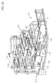
- Upper ends of the two rear posts 218a and 218b are equipped with wire attaching parts 220a and 220b, to which wires 311 (see Fig. 22 ) used for pulling up the rear frame 201 with a crane are attached.
- Insertion support plates 221a and 221b are fixed by welding to the lateral surfaces of the side plates 211a and 211b of the base frame 216, respectively.
- Pin holes 222a and 222b are formed through the lateral surfaces of the rear parts of the insertion support plates 221a and 221b and the side plates 211a and 211b.
- the rear frame 201 is put on the longitudinal ribs 122a and 122b of the main frame 120 of the vehicle main body 100 by making the horizontal flanges 214a and 214b of the base frame 216 be supported on the upper ends of the longitudinal ribs 122a and 122b of the main frame 120.
- the side plates 211a and 211b of the rear frame 201 are gradually inserted into the main frame 120, by which the insertion support plates 221a and 221b that are attached to the lateral surfaces of the side plates 211a and 211b, slide along and under the support plates 158a and 158b that are attached to the medial surfaces of the longitudinal ribs 122a and 122b, with upper surfaces of the tips of the insertion support plates 221a and 221b sliding along the slanted guiding parts of the support plates 158a and 158b.
- the side plates 211a and 211b of the rear frame 201 have been inserted in the main frame 120, the movement of the rear frame 201 in the vertical direction is restricted.
- the side plates 211a and 211b of the rear frame 201 are connected and integrated with the swing frame 101 of the vehicle main body 100 by inserting the positioning pins 301a and 301b into the pin holes 155a and 155b of the longitudinal ribs 122a and 122b and the pin holes 222a and 222b of the side plates 211a and 211b, inserting the bolt 302 into the hole 156 of the longitudinal rib 122a, 122b and the bolt hole 223 of the side plate 211a, 211b, and tightening up the bolt 302.
- the movement of the rear frame 201 in the vertical and longitudinal directions is restricted by the positioning pins 301a and 301b and the movement of the rear frame 201 in the transverse direction is restricted by the bolt 302.
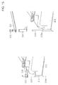
- a reinforcing plate 341 is attached to a part of the longitudinal rib 122b of the main frame 120 where the pin hole 155b for the positioning pin 301b is formed.
- the positioning pin 301b is inserted into the longitudinal rib 122b via the reinforcing plate 341.
- the positioning pin 301b has a lock plate 342 at its top. By fixing the lock plate 342 to the reinforcing plate 341 with a bolt 343, the positioning pin 301b is firmly fixed to the longitudinal rib 122b of the main frame 120 and securely prevented from coming off. The same goes for the positioning pin 301a on the left side unshown in Fig. 21 .
- the rear frame 201 has a plurality of mount rubbers 231 (four mount rubbers 231 for each side plate 211a, 211b in the illustrated example), a plurality of guide plates 232 (three guide plates 232 for each side plate 211a, 211b in the illustrated example), and a plurality of guide plates 233 (two guide plates 233 for each of the front and rear plates 212a and 212b in the illustrated example).
- the mount rubbers 231 are attached to the horizontal flange 214a, 214b of each side plate 211a, 211b of the base frame 216 via a reinforcing plate 230a, 230b at prescribed intervals in the longitudinal direction.
- the guide plates 232 are attached to the medial surface of each of the side plates 211a and 211b at prescribed intervals in the longitudinal direction.
- the guide plates 233 are attached to the medial surface of each of the front and rear plates 212a and 212b of the base frame 216 at prescribed intervals in the transverse direction.
- Each mount rubber 231 is a rubber member in a cylindrical shape.
- the battery storage structure 203 is mounted on the base frame 216 via the reinforcing plates 230a and 230b and the mount rubbers 231 and fixed to the base frame 216 by attaching nuts to the mount bolts 234.
- the mount rubbers 231 serve as antivibration rubbers for preventing vibrations of the battery storage structure 203 and the battery device 31 in the vertical direction.
- the guide plates 232 which are attached to the medial surfaces of the two side plates 211a and 211b at prescribed intervals and the guide plates 233 which are attached to the medial surfaces of the front and rear plates 212a and 212b at prescribed intervals, serve to stabilize the antivibration function of the mount rubbers 231, by fixing the positions of the battery storage structure 203 and the battery device 31 in the longitudinal and transverse directions while allowing the vibration of the battery storage structure 203 and the battery device 31 in the vertical direction.
- the guide plates 232 and 233 are formed of, for example, self-lubricating plastic material or rubber material that has undergone surface processing
- Fig. 6 is a perspective view of the battery storage structure 203 on which the battery device 31 has been mounted.
- Fig. 7 is an exploded perspective view of the battery storage structure 203.
- Fig. 8 is a perspective view of the battery storage structure 203.
- the battery storage structure 203 includes a battery table mount 251 mounted on the base frame 216 and multiple stages (three stages in the illustrated example) of battery tables 252, 253 and 254 mounted on the battery table mount 251.
- a plurality of battery modules 202 are set in the battery table mount 251 and on the battery tables 252, 253 and 254.
- the battery table 252, as the lowermost one of the multiple stages of battery tables 252, 253 and 254, is fixed on the battery table mount 251 with bolts.
- the multiple stages of battery tables 252, 253 and 254 are supported to be separate from each other in the vertical direction via posts 276a, 286a, 287a and 297b (explained later).
- the upper and lower ends of each post 276a, 286a, 287a, 297b are fixed to corresponding battery tables with bolts.
- the battery table mount 251 having a box-like shape similar to the base frame 216, includes a left side plate 261a, a right side plate 261b, a front plate 262a, a rear plate 262b and a base plate 263.
- the left and right side plates 261a and 261b are provided with horizontal flanges 264a and 264b protruding outward.
- the size of the box-shaped battery table mount 251 is set one step smaller than that of the box-shaped base frame 216 so that the side plates 261a and 261b and the front and rear plates 262a and 262b of the battery table mount 251 can be inserted into the space inside the side plates 211a and 211b and the front and rear plates 212a and 212b of the base frame 216 while being pressed and guided by the guide plates 232 and 233.
- the base plate 263 has a plurality of vent holes 265 for forming an upward air flow for cooling the battery modules 202.
- Each horizontal flange 264a, 264b of the battery table mount 251 has a plurality of (four in the illustrated example) bolt holes 266, into which the mount bolts 234 penetrating the mount rubbers 231 of the horizontal flange 214a, 214b of the base frame 216 are inserted.
- Each horizontal flange 264a, 264b further has a plurality of (three in the illustrated example) tapped bolt holes 267.
- the battery table 252 as the lowermost stage (first stage) includes a central plate 271a extending in the longitudinal direction, a left side plate 271b situated to the left of the central plate 271a and having substantially the same length as the central plate 271a, a right side plate 271c situated to the right rear of the central plate 271a and being shorter than the central plate 271a, and a framing member 272 supporting these plates and forming the exterior frame of the battery table 252.
- Each plate has a plurality of vent holes 273 for forming an upward air flow for cooling the battery modules 202.
- the central plate 271a is separated from the left and right side plates 271b and 271c by left partition plate 274a and right partition plate 274b which are erected on each sides of the central plate 271a. Lateral parts of the left and right side plates 271b and 271c are also provided with vertical partition plates 274c and 274d (see Fig. 6 , Fig. 8 , etc.) for positioning the battery modules 202.
- a plurality of mount plates 275 are provided at appropriate positions on the framing member 272.
- a post structure 276 having four posts 276a is attached to the rear part of the battery table 252 where the right side plate 271c is situated.
- the lower ends of the four posts 276a are supported on the top surface of the framing member 272.
- the lower ends of the posts 276a on the right-hand side are fixed to the right partition plate 274b with bolts, while the lower ends of the posts 276a on the left-hand side are fixed to the left partition plate 274a with bolts.
- the upper ends of the four posts 276a are connected by a top plate 276b having a plurality of tapped bolt holes.
- the lowermost battery table 252 is fixed on the battery table mount 251 by positioning the lowermost battery table 252 on the battery table mount 251 such that after the bolt holes of the mount plates 275 are aligned with the bolt holes of the horizontal flanges 264a and 264b of the battery table mount 251, bolts 255 are inserted into the bolt holes, and the bolts 255 are tightened up.
- the second battery table 253 also includes a central plate 281a, a left side plate 281b, a right side plate 281c, a framing member 282, vent holes 283, partition plates 284a, 284b, 284c and 284d, and a post structure 286 including four posts 286a and a top plate 286b having tapped bolt holes.
- the second battery table 253 further includes two additional upper posts 287a erected on the top surface of the framing member 286 and five additional lower posts 287b extending downward from the under surface of the framing member 282.
- the lower ends of the upper posts 287a are fixed to the top surface of the framing member 282 with bolts, while the upper ends of the lower posts 287b are fixed to the under surface of the framing member 282 with bolts.
- a mount plate 288a having tapped bolt holes is attached to the upper end of each upper post 287a, while a mount plate 288b having tapped bolt holes is attached to the lower end of each lower post 287b.
- the second battery table 253 is fixed on the lowermost battery table 252 by positioning the second battery table 253 on the lowermost battery table 252 such that after the bolt holes of the mount plates 288b of the lower posts 287b are aligned with the bolt holes of the framing member 272 of the lowermost battery table 252 and unshown bolt holes of the left and right side plates 281b and 281c are aligned with the bolt holes of the top plate 276b of the post structure 276 of the lowermost battery table 252, bolts are inserted into the bolt holes, and the bolts are tightened up.
- the third battery table 254 has a size and a shape corresponding to the rear part of the lowermost battery table 252 where the right side plate 271c is situated and corresponding to the rear part of the second battery table 253 where the right side plate 281c is situated.
- the third battery table 254 includes a central plate 291a, a left side plate 291b, a right side plate 291c, a framing member 292, vent holes 293, and partition plates 294a, 294b and 294c.
- a plurality of mount plates 295, each having a tapped bolt hole, are attached to appropriate parts of the under surface of the framing member 292.
- the third battery table 254 is fixed on the second battery table 253 by positioning the third battery table 254 on the second battery table 253 such that after the bolt holes of the mount plates 295 on the under surface of the framing member 292 are aligned with the bolt holes of the mount plates 288a of the upper posts 287a of the second battery table 253 and unshown bolt holes of the left and right side plates 291b and 291c are aligned with the bolt holes of the top plate 276b of the post structure 276 of the second battery table 253, bolts are inserted into the bolt holes, and the bolts are tightened up.
- a duct support plate 316 having a duct hole 316a is attached to a front part of the framing member 292 of the third battery table 254 where the right side plate 291c is situated.
- a duct 317 is connected to the duct hole 316a of the duct support plate 316.
- the other end of the duct 317 is connected to a duct hole 318 (see Fig. 2 ) formed through the partition plate 151 of the machine room 103.
- the duct 317 has a cooling fan (unshown) installed therein.
- the whole of the battery storage structure 203 storing the battery modules 202 is covered with a flexible sheet (unshown) having a hole formed at a position corresponding to the duct 317.
- the duct is inserted into the hole of the sheet and the part is sealed up by winding a string thereon.
- the cooling of the battery modules 202 can be performed efficiently during the operation of the hydraulic shovel 1 by discharging the air which flows upward through the vent holes 265, 273, 283 and 293 of the battery table mount 251 and the first through third battery tables 252, 253 and 254, into the machine room 103 with the cooling fan inside the duct 317 and then out of the machine room 103 to the outside with the cooling fan 30 of the machine room 103.
- Fig. 9 is a schematic diagram showing the details of the positional relationship between the battery table mount 251 and the base frame 216 of the rear frame 201 and the details of base structure of the two parts when the battery table mount 251 has been installed in the box-shaped base frame 216.
- the left-hand side of Fig. 9 is a cutaway view in which front parts of the base frame 216 and the battery table mount 251 have been cut away at a plane extending in the transverse direction.
- the right-hand side of Fig. 9 is a cutaway view in which right-hand parts of the base frame 216 and the battery table mount 251 have been cut away at a plane extending in the longitudinal direction.
- the base plate 263 of the battery table mount 251 has vent holes 265 as mentioned above.
- the interior surface (upper surface) of the base plate 263 is provided with two ribs 321 for positioning and holding the battery modules 202.
- the medial surfaces of the side plates 261a and 261b are equipped with battery support bolts 322 for fixing the battery modules 202.
- the battery table mount 251 has been attached on the base frame 216 of the rear frame 201 via the mount rubbers 231.
- a prescribed gap (clearance) 325 is formed between the battery table mount 251 and the base frame 216.
- the gap 325 functions as an air intake channel when the air around the battery modules 202 is heated due to the heating of the battery modules 202 and flows upward through the vent holes 265, 273, 283 and 293, by which the cooling of the battery modules 202 can be performed efficiently.
- the base plate 213 of the base frame 216 is a two-stage structure including a lower plate 213a and an upper plate 213b.
- the interior surface (upper surface) of the lower plate 213a is reinforced with two hollow square pipes 213c stretched in the transverse direction.
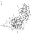
- the exterior surface (lower surface) of the lower plate 213a is flat and functions as a support part to be used for setting the vehicle rear part 200 on the forks 327 (see Fig. 23 ) of a forklift when the vehicle rear part 200 is separated from the vehicle main body 100 using the forklift.
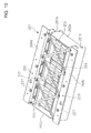
- Fig. 10 is a schematic diagram showing a state in which battery modules 202 have been stored in the battery table mount 251.
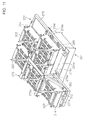
- Fig. 11 is a schematic diagram showing a state in which battery modules 202 have been mounted on the lowermost battery table 252 and the loaded battery table 252 has been attached on the battery table mount 251 shown in Fig. 10 .
- Fig. 12 is a schematic diagram showing a state in which battery modules 202 have been mounted on the second battery table 253 and the loaded battery table 253 has been attached on the lowermost battery table 252 shown in Fig. 11 .
- the aforementioned Fig. 6 shows a state in which battery modules 202 have been mounted on the third battery table 254 and the loaded battery table 254 has been attached on the second battery table 253 shown in Fig. 12 .
- the battery support bolts 322 attached to the battery table mount 251 and the battery support bolts 314 attached to the battery tables 252 to 254 are situated at the corners (four corners) of the battery modules 202.
- Each battery module 202 is held by the battery support bolts 314 or 322 and two clamp bars 329 stretched diagonally with respect to the top surface of the battery module 202.
- Each end of the clamp bar 329 is attached and fixed to the top of a corresponding battery support bolt 314 or 322.
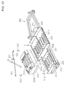
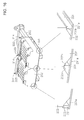
- Figs. 13 to 16 are schematic diagrams showing the details of a method for attaching a battery module 202 to the third battery table 254.
- Fig. 13 shows a state in which a battery module 202 has been detached from the right side plate 291c of the third battery table 254.
- Fig. 14 shows a state in which a battery module 202 has been attached to the right side plate 291c of the third battery table 254.
- Fig. 15 shows coupling relationship among the clamp bar 329, the battery support bolt 314 and the battery module 202, wherein the left-hand side shows a state in which the battery module 202 has been cramped and the right-hand side shows an end of the clamp bar 329 and a connecting part of the battery support bolt 314 in a disassembled state.
- Fig. 16 shows a state in which a battery module 202 has been positioned and held by ribs 331 provided on the bottom of the central plate 291a of the third battery table 254.
- a bracket 333 is slid onto the battery support bolt 314.
- a shoulder 202a to be in contact with the bracket 333 is formed.
- Two ribs 331 are attached to the front and rear of the right side plate 291c to adjoin the framing member 292.
- Three ribs 331 are attached to the front, center and rear of the central plate 291a.
- a shoulder 202b (see Fig. 16 ) to be in contact with the rib 331 is formed on each of the front lower edge and the rear lower edge of the battery module 202.
- the battery module 202 is set on the right side plate 291c while aligning the shoulders 202b situated on the lower edges of the battery module 202 with the ribs 331 on the right side plate 291c, by which the movement of the battery module 202 in the longitudinal direction is restricted.
- the four corners of the battery module 202 are in contact with or in close vicinity of corresponding battery support bolts 314, respectively.
- the brackets 333 are slid onto the battery support bolts 314, respectively, to let the brackets 333 be supported on the shoulders 202a at the four corners of the battery module 202.
- the two clamp bars 329 are stretched diagonally on the battery module 202 and the battery support bolts 314 are inserted into holes at the ends of the clamp bars 329 to make the battery support bolts 314 hold and support the two clamp bars 333.
- the clamp bars 329 serve as supports for preventing the brackets 333 from being detached outward.
- double lock nuts 335 are screwed onto a threaded part formed at the upper end of each battery support bolt 314 and the lock nuts 335 are tightened up. Consequently, the brackets 333 are pressed against the shoulders 202a at the four corners of the battery module 202 and the movement of the battery module 202 in the vertical direction is restricted.
- the battery module 202 can be detached by reversely conducting the above steps.
- two battery modules 202 are mounted on the central plate 291a of the third battery table 254. Also in this case, each battery module 202 can be attached according to the same procedure as the above explanation regarding the attachment of one battery module. In this case where two battery modules 202 are attached, however, two central battery support bolts 314 are shared by the two battery modules 202. Specifically, a bracket (not shown), having a shape fitting with two shoulders 202a at adjoining corners of the two battery modules 202, is slid onto each of the central battery support bolts 314 and the double lock nuts 335 are tightened up, by which the two battery modules 202 are held down together and their vertical movement is restricted.
- the mounting of battery modules on the battery table mount 251 can also be conducted similarly by use of the battery support bolts 322, the ribs 321 and the clamp bars 329.
- the battery modules 202 are mounted and fixed on the battery table mount 251, the lowermost battery table 252, the second battery table 253 and the third battery table 254 by the above method explained referring to Figs. 13 to 16 .
- the battery table mount 251, the lowermost battery table 252, the second battery table 253 and the third battery table 254 are stacked up and fixed one by one by the method explained referring to Fig. 6 and Figs. 10 to 12 , by which the battery storage structure 203 storing the battery device 31 is completed.
- the completed battery storage structure 203 is mounted and fixed on the rear frame 201 of the vehicle rear part 20.
- the stacking of the battery table mount 251 and the battery tables 252 to 254 and the mounting of the battery storage structure 203 on the rear frame 201 can be performed with ease by using a crane and the wires 311 attached to the wire attaching parts 312. The same goes for the detaching of the battery storage structure 203 from the base frame 216 and the separation of the battery table mount 251 and the battery tables 252 to 254.
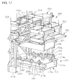
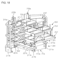
- Figs. 17 and 18 are schematic diagrams showing the mounting of the completed battery storage structure 203 on the rear frame 201 of the vehicle rear part 20, wherein Fig. 17 shows a state just before the battery storage structure 203 is mounted on the base frame 216 of the rear frame 201 and Fig. 18 shows a state in which the battery storage structure 203 has been mounted on the base frame 216.
- the battery modules 202 are unshown for convenience of illustration.
- the mount rubbers 231 have been attached to the horizontal flanges 214a and 214b of the base frame 216 via the reinforcing plates 230a and 230b, with the mount bolts 234 protruding from the mount rubbers 231.
- the battery storage structure 203 is mounted on the horizontal flanges 214a and 214b of the base frame 216 by lowering the battery storage structure 203 and inserting the mount bolts 234 of the base frame 216 into bolt holes 256 formed in flange parts 251a and 251b of the battery table mount 251. Then, nuts are attached to the mount bolts 234 and tightened up, by which the battery storage structure 203 is connected and integrated with the base frame 216. Conversely, by loosening and removing the nuts from the mount bolts 234 and lifting the battery storage structure 203, the battery storage structure 203 can be detached from the base frame 216.
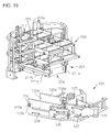
- Fig. 19 is a schematic diagram showing a state just before the rear frame 201 loaded with the battery storage structure 203 is mounted on the swing frame 101 (main frame 120) of the vehicle main body 100.
- Fig. 20 is a schematic diagram showing a state in which the rear frame 201 has been mounted on the swing frame 101 (main frame 120) of the vehicle main body 100.
- Fig. 21 is a schematic diagram magnifying a connecting part between the rear frame 201 and the swing frame 101 (main frame 120) using the positioning pins 301a and 301b and the bolt 302.
- the battery modules 202 and parts of the vehicle main body 100 exclusive of the swing frame 101 are unshown for convenience of illustration.
- the pin holes 155a and 155b and the holes 156 have been formed through the longitudinal ribs 122a and 122b of the main frame 12 of the swing frame 101, and the pin holes 222a and 222b and the bolt hole 223 have been formed through the side plates 211a and 211b of the base frame 216 of the rear frame 201.
- the support plates 158a and 158b each having the guiding part formed by the lower surface of its tip, have been attached to the front parts of the medial surfaces of the longitudinal ribs 122a and 122b, and the insertion support plates 221a and 221b have been attached to the lateral surfaces of the side plates 211a and 211b of the base frame 216.
- the rear frame 201 loaded with the battery storage structure 203 is put on the longitudinal ribs 122a and 122b of the main frame 120 of the vehicle main body 100 by lowering the rear frame 201 and making the horizontal flanges 214a and 214b of the base frame 216 be supported on the upper ends of the longitudinal ribs 122a and 122b of the main frame 120.
- the side plates 211a and 211b of the rear frame 201 are gradually inserted into the main frame 120, by which the insertion support plates 221a and 221b, the plates being attached to the lateral surfaces of the side plates 211a and 211b, slide along and under the support plates 158a and 158b, the plates being attached to the medial surfaces of the longitudinal ribs 122a and 122b, with the upper surfaces of the tips of the insertion support plates 221a and 221b sliding along the slanted guiding parts of the support plates 158a and 158b.
- the side plates 211a and 211b of the rear frame 201 have been inserted in the main frame 120, the movement of the rear frame 201 in the vertical direction is restricted.
- the positions of the base frame 216 (rear frame 201) and the main frame 120 (vehicle main body 100) are adjusted so that the pin holes 222a and 222b of the side plates 211a and 211b of the base frame 216 are aligned with the pin holes 155a and 155b of the longitudinal ribs 122a and 122b of the main frame 120.
- the rear frame 201 loaded with the battery storage structure 203 is connected and integrated with the swing frame 101 of the vehicle main body 100 by inserting the positioning pins 301a and 301b into the pin holes 155a and 155b and the pin holes 222a and 222b, inserting the bolt 302 into the hole 156 and the bolt hole 223, and tightening up the bolt 302.
- the movement of the rear frame 201 in the vertical and longitudinal directions is restricted by the positioning pins 301a and 301b, and the movement of the rear frame 201 in the transverse direction is restricted by the bolt 302.
- the mounting of the rear frame 201 on the swing frame 101 can be conducted with ease by attaching the wires 311 (see Fig. 22 ) to some wire attaching parts selected from the wire attaching parts 220a and 220b at the upper ends of the rear posts 218a and 218b and the wire attaching parts 312 of the battery tables 252 to 254 of the battery storage structure 203 (e.g., the wire attaching parts 220a and 220b of the rear posts 218a and 218b and the wire attaching parts 312 of the uppermost battery table 254) and pulling up the wires 311 using a crane.
- Fig. 22 is a schematic diagram showing the mounting, on the swing frame 101 using a crane, of the rear frame 201 that is loaded with the battery storage structure 203. Since the rear posts 218a and 218b of the rear frame 201 and the battery storage structure 203 in this embodiment are equipped with the wire attaching parts 220a, 220b and 312 as shown in Fig. 22 , the mounting of the rear frame 201 can be conduct with ease by attaching the wires 311 to arbitrarily selected wire attaching parts 220a, 220b, 312 and pulling up the wires 311 using a crane. The same goes for the detaching of the rear frame 201 from the swing frame 101.
- Fig. 23 is a schematic diagram showing the mounting, on the swing frame 101 using a forklift, of the rear frame 201 that is loaded with the battery storage structure 203. Since the support part 328 to be used for setting the rear frame 201 on the forks 327 of a forklift is provided on the lower surface of the base frame 216 (lower surface of the lower plate 213a of the base plate 213) and between the longitudinal ribs 122a and 122b of the swing frame 101 in this embodiment as shown in Fig. 23 , the mounting of the rear frame 201 can be conduct with ease also by using a forklift. The same goes for the detaching of the rear frame 201 from the swing frame 101.
- the rear cover 205 may either be attached immediately after the completion of the battery storage structure 203 or after mounting and fixing the rear frame on the swing frame.
- the upper swing structure 3 as the vehicle body of the hydraulic shovel 1 is made up of the vehicle main body 100 and the vehicle rear part 200, and the hydraulic shovel 1 is configured so that the vehicle rear part 200 is detachable from the vehicle main body 100 by removing the positioning pins 301a and 301b and the bolt 302. Therefore, the replacement of the vehicle rear part 200 is facilitated.
- the battery device 31 can be replaced easily and quickly and the working efficiency can be increased by preparing another vehicle rear part 200 loaded with a recharged battery device 31, detaching the already-attached vehicle rear part 200 from the vehicle main body 100 when the electricity amount of the battery device 31 on the vehicle rear part 200 has become insufficient, and attaching, to the vehicle main body 100, the prepared vehicle rear part 200 loaded with the recharged battery device 31.
- the maintenance of the battery device 31 can also be done with ease, by replacing the vehicle rear part 200 with another vehicle rear part 200 loaded with a recharged battery device 31 and moving the detached vehicle rear part 200 to maintenance facilities.
- the vehicle rear part 200 loaded with the currently used battery device 31 is detached from the vehicle main body 100 and another vehicle rear part 200 loaded with the battery device 31 of the different type is attached to the vehicle main body 100. Therefore, the battery device 31 can easily be replaced with different types of battery devices according to the progress of the battery technology.
- the rear frame 201 of the vehicle rear part 200 can be formed in various shapes differing in the length in the longitudinal direction, by which the number of the mounted batteries can be changed and adjusted to suit the operating time required of the electric hydraulic shovel.
- the battery room 204 is formed inside the rear cover 205. Therefore, the battery device 31 can be protected from shocks from the outside during the swing of the upper swing structure 3 (vehicle body).
- the vehicle rear part 200 By forming the vehicle rear part 200 in a shape imitating the counter weight, an external appearance having innovativeness can be given to the electric hydraulic shovel.
- the two longitudinal ribs 122a and 122b overhanging and extending to the underside of the vehicle rear part 200 are provided in the rear part of the main frame 120 of the vehicle main body 100.
- the rear frame 201 of the vehicle rear part 200 is equipped with the base frame 216 which couples with the two longitudinal ribs 122a and 122b of the main frame 120 from above.
- the base frame 216 mounted on the two longitudinal ribs 122a and 122b of the main frame 120 is fixed on the two longitudinal ribs 122a and 122b. Therefore, the movement of the rear frame 201 in the transverse direction is restricted by the base frame 216 and the two longitudinal ribs 122a and 122b of the main frame 120. Consequently, the vehicle rear part 200 can be held and fixed stably with respect to the vehicle main body 100.
- the base frame 216 mounted on the two longitudinal ribs 122a and 122b of the main frame 120 is fixed on the two longitudinal ribs 122a and 122b and prevented from coming off using the positioning pins 301a and 301b and the bolt 302.
- the whole of the vehicle rear part 200 is detachable from the two longitudinal ribs 122a and 122b by removing the positioning pins 301a and 301b and the bolt 302. Therefore, the whole of the vehicle rear part 200 can be attached to and detached from the vehicle main body 100 with ease while leaving the battery device 31 mounted on the vehicle rear part 20.
- the rear frame 201 is mounted on the two longitudinal ribs 122a and 122b of the main frame 120 by making the horizontal flanges 214a and 214b of the base frame 216 be supported on the upper ends of the two longitudinal ribs 122a and 122b. Therefore, the movement of the rear frame 201 in the transverse direction is restricted by the two side plates 211a and 211b of the base frame 216 and the two longitudinal ribs 122a and 122b of the main frame 120, and the movement of the rear frame 201 in the vertical direction is restricted by the horizontal flanges 214a and 214b of the base frame 216 and the two longitudinal ribs 122a and 122b of the main frame 120. Consequently, the vehicle rear part 200 can be stably fixed to the vehicle main body 100.
- the support part to be used for setting the vehicle rear part 200 on the forks 327 of a forklift is provided on the lower surface of the base frame 216 (lower surface of the lower plate 213a of the base plate 213) and between the two longitudinal ribs 122a and 122b of the main frame 120.
- the vehicle rear part 200 is movable with respect to the vehicle main body 100 using the forklift. Therefore, the vehicle rear part 200 can be replaced safely by use of a forklift even when the vehicle rear part 200 loaded with the battery device 31 is heavy.
- the vehicle rear part 200 and the battery storage structure 203 are equipped with the wire attaching parts 220a, 220b and 312.
- the vehicle rear part 200 is movable with respect to the vehicle main body 100 using a crane. Therefore, the vehicle rear part 200 can be replaced safely by use of a crane even when the vehicle rear part 200 loaded with the battery storage structure 203 is heavy.
- the base frame 216 is provided with a plurality of mount rubbers 231.
- the battery storage structure 203 is attached on the base frame 216 with the mount bolts 234 via the mount rubbers 231. Therefore, vertical vibrations of the battery storage structure 203 and the battery device 31 during the operation of the hydraulic shovel 1 are absorbed, by which the battery device 31 and the battery storage structure 203 can be protected from vertical operating vibrations of the hydraulic shovel 1.
- the battery table mount 251 By standardizing the lowermost attaching part of the battery storage structure 203 (i.e., the battery table mount 251), it becomes possible to mount various types of battery storage structures differing in the configuration. Consequently, various types of batteries can easily be mounted according to the progress of the battery technology.
- the battery storage structure 203 is equipped with a plurality of wire attaching parts 312.
- the battery storage structure 203 is movable in the vertical direction with respect to the base frame 216 by using a crane. Therefore, the battery storage structure 203 can be replaced safely by use of a crane even when the battery storage structure 203 loaded with the battery device 31 is heavy.
- the battery storage structure 203 is made up of the battery table mount 251 and multiple stages of battery tables 252 to 254.
- the battery table mount 251 and the multiple stages of battery tables 252 to 254 are supported and fixed to be separate from each other in the vertical direction via the posts 276a, 286a, 287a and 297b. Therefore, a lot of battery modules can be mounted and the attaching/detaching of the battery modules can be conducted safely and easily.
- the rear cover 205 of the vehicle rear part 200 covers a rear part, a right-hand part, a left-hand part and a top part of the vehicle rear part 200.
- the machine room 103 is separated from the other parts of the vehicle main body 100 by the partition plates 151 and 152.
- the battery room 204 is insulated by the partition plates 151 and 152 from heat sources such as the electric motor 18, the inverter 19, etc., in the machine room 103 and a space preventing effects of heat on the battery modules 202 of the battery device 31 arranged in the battery room 204 is secured. Therefore, the temperature rise as a cause of deterioration of the battery device 31 can be prevented.
- the overhanging part 122 of the main frame 120 is formed by the two longitudinal ribs 122a and 122b in the above embodiment, the overhanging part 122 may be configured differently as long as the structure of the overhanging part 122 can support the base frame 216 of the vehicle rear part 200.
- the overhanging part 122 can be a frame structure having a part supporting the base frame 216.
- the overhanging part 122 may also be formed of three longitudinal ribs including a third longitudinal rib that supports the central part of the base frame 216.
- the base frame 216 in the above embodiment includes the two side plates 211a and 211b to be arranged inside the two longitudinal ribs 122a and 122b of the main frame 120, the base plate 213 connecting the lower ends of the two side plates 211a and 211b, and the outward horizontal flanges 214a and 214b provided at the upper ends of the two side plates 211a and 211b, respectively, and the rear frame 201 is mounted on the two longitudinal ribs 122a and 122b by making the horizontal flanges 214a and 214b be supported on the upper ends of the two longitudinal ribs 122a and 122b.
- the present invention is not to be restricted to this configuration.
- the base frame 216 may include two side plates to be arranged outside the two longitudinal ribs 122a and 122b of the main frame 120 and a top plate connecting the upper ends of the side plates, and the rear frame 201 may be mounted on the two longitudinal ribs 122a and 122b by making the top plate be supported on the upper ends of the two longitudinal ribs 122a and 122b.
- the battery storage structure 203 in the above embodiment includes the battery table mount 251 and the battery tables 252 to 254, the number of stages of the battery tables 252 to 254 may be changed properly, depending on the number of batteries to be mounted.
- the configuration of the battery tables 252 to 254 may also be changed properly, depending on the type of the battery device to be mounted.
- hydraulic shovel 1 has been illustrated in the above embodiment as an example of the electric construction machine, the present invention is not to be restricted to hydraulic shovels; the present invention is applicable also to a wide range of other construction machines such as wheel loaders, hydraulic cranes, etc.
Landscapes
- Engineering & Computer Science (AREA)
- Mining & Mineral Resources (AREA)
- Civil Engineering (AREA)
- General Engineering & Computer Science (AREA)
- Structural Engineering (AREA)
- Chemical & Material Sciences (AREA)
- Combustion & Propulsion (AREA)
- Transportation (AREA)
- Mechanical Engineering (AREA)
- Arrangement Or Mounting Of Propulsion Units For Vehicles (AREA)
Applications Claiming Priority (2)
| Application Number | Priority Date | Filing Date | Title |
|---|---|---|---|
| JP2010136384 | 2010-06-15 | ||
| PCT/JP2011/062978 WO2011158686A1 (fr) | 2010-06-15 | 2011-06-06 | Machine de construction électrique |
Publications (3)
| Publication Number | Publication Date |
|---|---|
| EP2584101A1 true EP2584101A1 (fr) | 2013-04-24 |
| EP2584101A4 EP2584101A4 (fr) | 2016-04-06 |
| EP2584101B1 EP2584101B1 (fr) | 2017-05-10 |
Family
ID=45348092
Family Applications (1)
| Application Number | Title | Priority Date | Filing Date |
|---|---|---|---|
| EP11795594.8A Active EP2584101B1 (fr) | 2010-06-15 | 2011-06-06 | Machine de construction électrique |
Country Status (6)
| Country | Link |
|---|---|
| US (1) | US20130078071A1 (fr) |
| EP (1) | EP2584101B1 (fr) |
| JP (1) | JP5626813B2 (fr) |
| KR (1) | KR101815331B1 (fr) |
| CN (1) | CN102947512B (fr) |
| WO (1) | WO2011158686A1 (fr) |
Cited By (9)
| Publication number | Priority date | Publication date | Assignee | Title |
|---|---|---|---|---|
| FR3018797A1 (fr) * | 2014-03-19 | 2015-09-25 | Geismar Ancien Ets L | Machine de levage de poids, comprenant un dispositif de fleche de grue et un dispositif de contrepoids |
| EP3000945A1 (fr) * | 2014-09-29 | 2016-03-30 | Honda Motor Co., Ltd. | Structure de montage à composant montable/démontable pour une machine de travail |
| EP3222453A4 (fr) * | 2014-11-17 | 2018-02-14 | Hitachi Automotive Systems, Ltd. | Élément de protection de batterie |
| WO2021098984A1 (fr) * | 2019-11-18 | 2021-05-27 | Caterpillar Sarl | Engin de chantier |
| CN114164876A (zh) * | 2020-09-10 | 2022-03-11 | 住友建机株式会社 | 施工机械 |
| FR3125521A1 (fr) * | 2021-07-20 | 2023-01-27 | Manitou Bf | Engin de travail comprenant des éléments de batterie |
| FR3137874A1 (fr) * | 2022-07-18 | 2024-01-19 | Manitou Bf | Engin de travail avec une cabine située latéralement et un module de batteries fixé sous la cabine |
| WO2024076907A1 (fr) * | 2022-10-03 | 2024-04-11 | Doosan Bobcat North America, Inc. | Systèmes et procédés de commande de machines électriques à alimentation électrique |
| EP4421245A1 (fr) * | 2023-02-27 | 2024-08-28 | Takeuchi Mfg. Co., Ltd. | Véhicule de travail |
Families Citing this family (33)
| Publication number | Priority date | Publication date | Assignee | Title |
|---|---|---|---|---|
| JP5706110B2 (ja) * | 2010-07-29 | 2015-04-22 | プレス工業株式会社 | 建設機械のキャブフレーム構造 |
| JP5814577B2 (ja) * | 2011-03-24 | 2015-11-17 | 株式会社小松製作所 | 電動式作業車両及びそのバッテリ保持構造 |
| JP5814578B2 (ja) | 2011-03-24 | 2015-11-17 | 株式会社小松製作所 | 電動式作業車両及びそのベースフレーム |
| JP5781920B2 (ja) * | 2011-12-28 | 2015-09-24 | ヤンマー株式会社 | 電動作業車両 |
| KR101868170B1 (ko) * | 2013-07-17 | 2018-06-15 | 현대건설기계 주식회사 | 굴삭기의 카울 서포트 구조 |
| KR20170046366A (ko) * | 2015-10-21 | 2017-05-02 | 현대중공업 주식회사 | 작업기계 |
| JP6495193B2 (ja) * | 2016-01-20 | 2019-04-03 | 株式会社日立建機ティエラ | 小型の建設機械 |
| US10184227B2 (en) * | 2016-06-21 | 2019-01-22 | Kubota Corporation | Work machine |
| US11069936B2 (en) * | 2016-07-22 | 2021-07-20 | Kubota Corporation | Electric work vehicle |
| JP6829152B2 (ja) * | 2017-06-06 | 2021-02-10 | 株式会社神戸製鋼所 | 溶接装置 |
| JP7030544B2 (ja) * | 2018-01-24 | 2022-03-07 | 株式会社小松製作所 | 建設機械 |
| GB2572356B (en) * | 2018-03-27 | 2022-09-14 | Bamford Excavators Ltd | Load-handling vehicle |
| EP4406780A3 (fr) * | 2019-06-26 | 2025-01-08 | Kubota Corporation | Machine de travail |
| WO2021042257A1 (fr) * | 2019-09-03 | 2021-03-11 | Guangxi Liugong Machinery Co., Ltd. | Ensemble de stockage d'énergie |
| US12180672B2 (en) | 2020-03-02 | 2024-12-31 | Doosan Bobcat North America, Inc. | Electrically powered power machine |
| EP4115025A4 (fr) * | 2020-03-06 | 2023-12-27 | Manitou Equipment America, LLC | Chargeur entraîné par moteur électrique doté d'un système hydraulique alimenté par un moteur électrique |
| CN111319442B (zh) * | 2020-03-23 | 2024-09-17 | 国机重工集团常林有限公司 | 电动工程机械锂电池组抗振、防撞安装结构 |
| JP7422610B2 (ja) * | 2020-06-02 | 2024-01-26 | ヤンマーホールディングス株式会社 | 電動式建設機械 |
| US11161415B1 (en) * | 2020-09-28 | 2021-11-02 | Oshkosh Corporation | System and method for electronic power take-off controls |
| JP7502458B2 (ja) * | 2020-10-30 | 2024-06-18 | 本田技研工業株式会社 | 作業車 |
| JP7393323B2 (ja) * | 2020-12-18 | 2023-12-06 | ヤンマーホールディングス株式会社 | 建設機械 |
| CN112688001A (zh) * | 2021-01-25 | 2021-04-20 | 徐工集团工程机械股份有限公司科技分公司 | 一种电动装载机用电池布置结构 |
| JP7634413B2 (ja) * | 2021-04-15 | 2025-02-21 | 株式会社小松製作所 | 電動ショベル |
| CA3220521A1 (fr) | 2021-09-02 | 2023-03-09 | Brent DURKIN | Agencements de bras de levage pour machines a moteur |
| JP7750713B2 (ja) * | 2021-10-21 | 2025-10-07 | ヤンマーホールディングス株式会社 | 電動式作業機械 |
| JP2023160539A (ja) * | 2022-04-22 | 2023-11-02 | ヤンマーホールディングス株式会社 | 電動式作業機械 |
| EP4306724A1 (fr) * | 2022-07-15 | 2024-01-17 | Yanmar Holdings Co., Ltd. | Machine de travail électrique |
| US12126039B2 (en) * | 2022-08-11 | 2024-10-22 | Curtis Randolph | Battery placement rack |
| JP7733036B2 (ja) * | 2023-02-27 | 2025-09-02 | 株式会社竹内製作所 | 作業用車両 |
| KR20250015277A (ko) * | 2023-07-25 | 2025-02-03 | 에이치디현대인프라코어 주식회사 | 전동식 건설기계 |
| US20250084616A1 (en) * | 2023-09-11 | 2025-03-13 | Yanmar Holdings Co., Ltd. | Work machine |
| KR102801112B1 (ko) * | 2024-06-28 | 2025-04-28 | 볼보 컨스트럭션 이큅먼트 에이비 | 건설기계의 배터리 조립체 및 그 조립 방법 |
| DE102025140893A1 (de) | 2024-10-10 | 2026-04-16 | Caterpillar Inc. | Batteriemodulanordnung für eine maschine |
Family Cites Families (19)
| Publication number | Priority date | Publication date | Assignee | Title |
|---|---|---|---|---|
| US3497090A (en) * | 1968-04-03 | 1970-02-24 | Allis Chalmers Mfg Co | Combined battery case and counterweight |
| US3721353A (en) * | 1970-12-14 | 1973-03-20 | Clark Equipment Co | Combined battery case,counterweight and overhead guard |
| SE422932B (sv) * | 1980-06-02 | 1982-04-05 | Atlas Copco Ab | Batteridriven lastmaskin med ett lyftorgan for batteripaket samt en fristaende stodpall for att uppbera batteripaketet |
| JPH0717265A (ja) * | 1993-07-06 | 1995-01-20 | Nippon Home Keizai Kenkyusho:Kk | 電気自動車動力用二次電池の自動車への装架装置 |
| JP2963860B2 (ja) * | 1995-06-01 | 1999-10-18 | 新キャタピラー三菱株式会社 | 建設機械における上部旋回体のフレーム構造 |
| JP3030242B2 (ja) * | 1995-11-28 | 2000-04-10 | 新キャタピラー三菱株式会社 | 建設機械 |
| US5760569A (en) * | 1997-02-26 | 1998-06-02 | Chase, Jr.; Robert B. | Replaceable battery module for electric vehicle |
| JP3782004B2 (ja) * | 2001-11-29 | 2006-06-07 | 株式会社クボタ | フロントローダとバックホーを装着できるトラクタ |
| CN100482901C (zh) * | 2004-03-29 | 2009-04-29 | 株式会社久保田 | 具有旋转台的旋转作业机 |
| JP4123229B2 (ja) * | 2004-12-24 | 2008-07-23 | コベルコ建機株式会社 | 建設機械のカウンタウェイト装置 |
| EP1985767B1 (fr) * | 2006-02-07 | 2017-03-22 | Takeuchi MFG.Co.,Ltd. | Véhicule industriel à propulsion électrique |
| JP4730834B2 (ja) * | 2006-06-05 | 2011-07-20 | キャタピラー エス エー アール エル | 作業機械におけるカウンタウエイト |
| JP4185118B2 (ja) * | 2006-06-27 | 2008-11-26 | 日立建機株式会社 | 建設機械 |
| DE102006031461A1 (de) * | 2006-07-07 | 2008-01-10 | Jungheinrich Aktiengesellschaft | Batteriewechselsystem für ein batteriebetriebenes Flurförderzeug |
| JP2008019616A (ja) * | 2006-07-12 | 2008-01-31 | Hitachi Constr Mach Co Ltd | 電動式建設機械 |
| JP2008044408A (ja) * | 2006-08-10 | 2008-02-28 | Hitachi Constr Mach Co Ltd | バッテリ駆動式建設機械のバッテリ保持構造 |
| JP2008075372A (ja) * | 2006-09-22 | 2008-04-03 | Hitachi Constr Mach Co Ltd | 建設機械の間隙調整装置 |
| JP2008127762A (ja) * | 2006-11-16 | 2008-06-05 | Hitachi Constr Mach Co Ltd | 建設機械 |
| DE102009045340A1 (de) * | 2009-09-18 | 2011-03-24 | Jungheinrich Aktiengesellschaft | Batterieentnahmegerät für ein Fahrzeug, insbesondere Elektroflurförderzeug, und Verriegelungseinrichtung für ein solches Batterieentnahmegerät |
-
2011
- 2011-06-06 CN CN201180029627.4A patent/CN102947512B/zh active Active
- 2011-06-06 WO PCT/JP2011/062978 patent/WO2011158686A1/fr not_active Ceased
- 2011-06-06 KR KR1020127032662A patent/KR101815331B1/ko not_active Expired - Fee Related
- 2011-06-06 US US13/702,363 patent/US20130078071A1/en not_active Abandoned
- 2011-06-06 EP EP11795594.8A patent/EP2584101B1/fr active Active
- 2011-06-06 JP JP2012520376A patent/JP5626813B2/ja active Active
Cited By (14)
| Publication number | Priority date | Publication date | Assignee | Title |
|---|---|---|---|---|
| FR3018797A1 (fr) * | 2014-03-19 | 2015-09-25 | Geismar Ancien Ets L | Machine de levage de poids, comprenant un dispositif de fleche de grue et un dispositif de contrepoids |
| EP3000945A1 (fr) * | 2014-09-29 | 2016-03-30 | Honda Motor Co., Ltd. | Structure de montage à composant montable/démontable pour une machine de travail |
| EP3222453A4 (fr) * | 2014-11-17 | 2018-02-14 | Hitachi Automotive Systems, Ltd. | Élément de protection de batterie |
| US12565753B2 (en) | 2019-11-18 | 2026-03-03 | Caterpillar Sarl | Construction machine |
| WO2021098984A1 (fr) * | 2019-11-18 | 2021-05-27 | Caterpillar Sarl | Engin de chantier |
| CN114164876A (zh) * | 2020-09-10 | 2022-03-11 | 住友建机株式会社 | 施工机械 |
| FR3125521A1 (fr) * | 2021-07-20 | 2023-01-27 | Manitou Bf | Engin de travail comprenant des éléments de batterie |
| FR3137874A1 (fr) * | 2022-07-18 | 2024-01-19 | Manitou Bf | Engin de travail avec une cabine située latéralement et un module de batteries fixé sous la cabine |
| US12565409B2 (en) | 2022-07-18 | 2026-03-03 | Manitou Bf | Construction vehicle with a lateral cab and a battery module fastened beneath the cab |
| EP4309937A1 (fr) * | 2022-07-18 | 2024-01-24 | Manitou Bf | Engin de travail avec une cabine situee lateralement et un module de batteries fixe sous la cabine |
| WO2024076907A1 (fr) * | 2022-10-03 | 2024-04-11 | Doosan Bobcat North America, Inc. | Systèmes et procédés de commande de machines électriques à alimentation électrique |
| US12565757B2 (en) | 2022-10-03 | 2026-03-03 | Doosan Bobcat North America, Inc. | Systems and methods for control of electrically powered power machines |
| US12571184B2 (en) | 2022-10-03 | 2026-03-10 | Doosan Bobcat North America, Inc. | Systems and methods for control of electrically powered power machines |
| EP4421245A1 (fr) * | 2023-02-27 | 2024-08-28 | Takeuchi Mfg. Co., Ltd. | Véhicule de travail |
Also Published As
| Publication number | Publication date |
|---|---|
| KR101815331B1 (ko) | 2018-01-04 |
| KR20130095649A (ko) | 2013-08-28 |
| US20130078071A1 (en) | 2013-03-28 |
| EP2584101A4 (fr) | 2016-04-06 |
| EP2584101B1 (fr) | 2017-05-10 |
| CN102947512B (zh) | 2015-05-27 |
| JPWO2011158686A1 (ja) | 2013-08-19 |
| WO2011158686A1 (fr) | 2011-12-22 |
| JP5626813B2 (ja) | 2014-11-19 |
| CN102947512A (zh) | 2013-02-27 |
Similar Documents
| Publication | Publication Date | Title |
|---|---|---|
| EP2584101B1 (fr) | Machine de construction électrique | |
| EP2584100B1 (fr) | Machine de construction électrique | |
| EP2540915B1 (fr) | Machine de construction électrique | |
| US10000908B2 (en) | Hybrid-type working machine | |
| US12371877B2 (en) | Construction equipment | |
| US9790662B2 (en) | Hybrid-type working machine | |
| US9611624B2 (en) | Construction machine | |
| US12146295B2 (en) | Electric work machine | |
| EP2256259A2 (fr) | Machine de travail hybride | |
| EP4299839A1 (fr) | Machine de travail électrique | |
| US20250305242A1 (en) | Electric Work Vehicle | |
| JP2022086178A (ja) | 燃料電池モジュールとその製造方法 | |
| CN106978827B (zh) | 挖土机 | |
| CN214928919U (zh) | 一种汽车电池支架、汽车供电装置及汽车 | |
| US20250091442A1 (en) | Electric work machine | |
| US20230339305A1 (en) | Electric Work Machine | |
| EP4524326A1 (fr) | Machine de travail électrique | |
| US12618225B1 (en) | Working vehicle | |
| US20250305240A1 (en) | Working Vehicle | |
| US20260103870A1 (en) | Work machine |
Legal Events
| Date | Code | Title | Description |
|---|---|---|---|
| PUAI | Public reference made under article 153(3) epc to a published international application that has entered the european phase |
Free format text: ORIGINAL CODE: 0009012 |
|
| 17P | Request for examination filed |
Effective date: 20130115 |
|
| AK | Designated contracting states |
Kind code of ref document: A1 Designated state(s): AL AT BE BG CH CY CZ DE DK EE ES FI FR GB GR HR HU IE IS IT LI LT LU LV MC MK MT NL NO PL PT RO RS SE SI SK SM TR |
|
| DAX | Request for extension of the european patent (deleted) | ||
| RA4 | Supplementary search report drawn up and despatched (corrected) |
Effective date: 20160307 |
|
| RIC1 | Information provided on ipc code assigned before grant |
Ipc: E02F 9/08 20060101ALI20160301BHEP Ipc: E02F 9/00 20060101AFI20160301BHEP |
|
| GRAP | Despatch of communication of intention to grant a patent |
Free format text: ORIGINAL CODE: EPIDOSNIGR1 |
|
| STAA | Information on the status of an ep patent application or granted ep patent |
Free format text: STATUS: GRANT OF PATENT IS INTENDED |
|
| INTG | Intention to grant announced |
Effective date: 20161123 |
|
| RIN1 | Information on inventor provided before grant (corrected) |
Inventor name: NOGUCHI, AKIRA Inventor name: YUNOUE, MASAYUKI |
|
| GRAS | Grant fee paid |
Free format text: ORIGINAL CODE: EPIDOSNIGR3 |
|
| GRAA | (expected) grant |
Free format text: ORIGINAL CODE: 0009210 |
|
| STAA | Information on the status of an ep patent application or granted ep patent |
Free format text: STATUS: THE PATENT HAS BEEN GRANTED |
|
| RAP1 | Party data changed (applicant data changed or rights of an application transferred) |
Owner name: HITACHI CONSTRUCTION MACHINERY TIERRA CO., LTD. |
|
| AK | Designated contracting states |
Kind code of ref document: B1 Designated state(s): AL AT BE BG CH CY CZ DE DK EE ES FI FR GB GR HR HU IE IS IT LI LT LU LV MC MK MT NL NO PL PT RO RS SE SI SK SM TR |
|
| REG | Reference to a national code |
Ref country code: GB Ref legal event code: FG4D |
|
| REG | Reference to a national code |
Ref country code: AT Ref legal event code: REF Ref document number: 892462 Country of ref document: AT Kind code of ref document: T Effective date: 20170515 Ref country code: CH Ref legal event code: EP |
|
| REG | Reference to a national code |
Ref country code: IE Ref legal event code: FG4D Ref country code: NL Ref legal event code: FP |
|
| REG | Reference to a national code |
Ref country code: DE Ref legal event code: R096 Ref document number: 602011037878 Country of ref document: DE |
|
| REG | Reference to a national code |
Ref country code: LT Ref legal event code: MG4D |
|
| REG | Reference to a national code |
Ref country code: AT Ref legal event code: MK05 Ref document number: 892462 Country of ref document: AT Kind code of ref document: T Effective date: 20170510 |
|
| PG25 | Lapsed in a contracting state [announced via postgrant information from national office to epo] |
Ref country code: FI Free format text: LAPSE BECAUSE OF FAILURE TO SUBMIT A TRANSLATION OF THE DESCRIPTION OR TO PAY THE FEE WITHIN THE PRESCRIBED TIME-LIMIT Effective date: 20170510 Ref country code: AT Free format text: LAPSE BECAUSE OF FAILURE TO SUBMIT A TRANSLATION OF THE DESCRIPTION OR TO PAY THE FEE WITHIN THE PRESCRIBED TIME-LIMIT Effective date: 20170510 Ref country code: HR Free format text: LAPSE BECAUSE OF FAILURE TO SUBMIT A TRANSLATION OF THE DESCRIPTION OR TO PAY THE FEE WITHIN THE PRESCRIBED TIME-LIMIT Effective date: 20170510 Ref country code: LT Free format text: LAPSE BECAUSE OF FAILURE TO SUBMIT A TRANSLATION OF THE DESCRIPTION OR TO PAY THE FEE WITHIN THE PRESCRIBED TIME-LIMIT Effective date: 20170510 Ref country code: NO Free format text: LAPSE BECAUSE OF FAILURE TO SUBMIT A TRANSLATION OF THE DESCRIPTION OR TO PAY THE FEE WITHIN THE PRESCRIBED TIME-LIMIT Effective date: 20170810 Ref country code: GR Free format text: LAPSE BECAUSE OF FAILURE TO SUBMIT A TRANSLATION OF THE DESCRIPTION OR TO PAY THE FEE WITHIN THE PRESCRIBED TIME-LIMIT Effective date: 20170811 Ref country code: ES Free format text: LAPSE BECAUSE OF FAILURE TO SUBMIT A TRANSLATION OF THE DESCRIPTION OR TO PAY THE FEE WITHIN THE PRESCRIBED TIME-LIMIT Effective date: 20170510 |
|
| PG25 | Lapsed in a contracting state [announced via postgrant information from national office to epo] |
Ref country code: PL Free format text: LAPSE BECAUSE OF FAILURE TO SUBMIT A TRANSLATION OF THE DESCRIPTION OR TO PAY THE FEE WITHIN THE PRESCRIBED TIME-LIMIT Effective date: 20170510 Ref country code: LV Free format text: LAPSE BECAUSE OF FAILURE TO SUBMIT A TRANSLATION OF THE DESCRIPTION OR TO PAY THE FEE WITHIN THE PRESCRIBED TIME-LIMIT Effective date: 20170510 Ref country code: SE Free format text: LAPSE BECAUSE OF FAILURE TO SUBMIT A TRANSLATION OF THE DESCRIPTION OR TO PAY THE FEE WITHIN THE PRESCRIBED TIME-LIMIT Effective date: 20170510 Ref country code: BG Free format text: LAPSE BECAUSE OF FAILURE TO SUBMIT A TRANSLATION OF THE DESCRIPTION OR TO PAY THE FEE WITHIN THE PRESCRIBED TIME-LIMIT Effective date: 20170810 Ref country code: RS Free format text: LAPSE BECAUSE OF FAILURE TO SUBMIT A TRANSLATION OF THE DESCRIPTION OR TO PAY THE FEE WITHIN THE PRESCRIBED TIME-LIMIT Effective date: 20170510 Ref country code: IS Free format text: LAPSE BECAUSE OF FAILURE TO SUBMIT A TRANSLATION OF THE DESCRIPTION OR TO PAY THE FEE WITHIN THE PRESCRIBED TIME-LIMIT Effective date: 20170910 |
|
| PG25 | Lapsed in a contracting state [announced via postgrant information from national office to epo] |
Ref country code: EE Free format text: LAPSE BECAUSE OF FAILURE TO SUBMIT A TRANSLATION OF THE DESCRIPTION OR TO PAY THE FEE WITHIN THE PRESCRIBED TIME-LIMIT Effective date: 20170510 Ref country code: CZ Free format text: LAPSE BECAUSE OF FAILURE TO SUBMIT A TRANSLATION OF THE DESCRIPTION OR TO PAY THE FEE WITHIN THE PRESCRIBED TIME-LIMIT Effective date: 20170510 Ref country code: DK Free format text: LAPSE BECAUSE OF FAILURE TO SUBMIT A TRANSLATION OF THE DESCRIPTION OR TO PAY THE FEE WITHIN THE PRESCRIBED TIME-LIMIT Effective date: 20170510 Ref country code: RO Free format text: LAPSE BECAUSE OF FAILURE TO SUBMIT A TRANSLATION OF THE DESCRIPTION OR TO PAY THE FEE WITHIN THE PRESCRIBED TIME-LIMIT Effective date: 20170510 Ref country code: SK Free format text: LAPSE BECAUSE OF FAILURE TO SUBMIT A TRANSLATION OF THE DESCRIPTION OR TO PAY THE FEE WITHIN THE PRESCRIBED TIME-LIMIT Effective date: 20170510 |
|
| REG | Reference to a national code |
Ref country code: CH Ref legal event code: PL |
|
| REG | Reference to a national code |
Ref country code: DE Ref legal event code: R097 Ref document number: 602011037878 Country of ref document: DE |
|
| PG25 | Lapsed in a contracting state [announced via postgrant information from national office to epo] |
Ref country code: IT Free format text: LAPSE BECAUSE OF FAILURE TO SUBMIT A TRANSLATION OF THE DESCRIPTION OR TO PAY THE FEE WITHIN THE PRESCRIBED TIME-LIMIT Effective date: 20170510 Ref country code: SM Free format text: LAPSE BECAUSE OF FAILURE TO SUBMIT A TRANSLATION OF THE DESCRIPTION OR TO PAY THE FEE WITHIN THE PRESCRIBED TIME-LIMIT Effective date: 20170510 |
|
| PLBE | No opposition filed within time limit |
Free format text: ORIGINAL CODE: 0009261 |
|
| STAA | Information on the status of an ep patent application or granted ep patent |
Free format text: STATUS: NO OPPOSITION FILED WITHIN TIME LIMIT |
|
| REG | Reference to a national code |
Ref country code: IE Ref legal event code: MM4A |
|
| REG | Reference to a national code |
Ref country code: FR Ref legal event code: ST Effective date: 20180228 |
|
| 26N | No opposition filed |
Effective date: 20180213 |
|
| PG25 | Lapsed in a contracting state [announced via postgrant information from national office to epo] |
Ref country code: IE Free format text: LAPSE BECAUSE OF NON-PAYMENT OF DUE FEES Effective date: 20170606 Ref country code: LU Free format text: LAPSE BECAUSE OF NON-PAYMENT OF DUE FEES Effective date: 20170606 Ref country code: CH Free format text: LAPSE BECAUSE OF NON-PAYMENT OF DUE FEES Effective date: 20170630 Ref country code: LI Free format text: LAPSE BECAUSE OF NON-PAYMENT OF DUE FEES Effective date: 20170630 |
|
| PG25 | Lapsed in a contracting state [announced via postgrant information from national office to epo] |
Ref country code: SI Free format text: LAPSE BECAUSE OF FAILURE TO SUBMIT A TRANSLATION OF THE DESCRIPTION OR TO PAY THE FEE WITHIN THE PRESCRIBED TIME-LIMIT Effective date: 20170510 Ref country code: FR Free format text: LAPSE BECAUSE OF NON-PAYMENT OF DUE FEES Effective date: 20170710 |
|
| REG | Reference to a national code |
Ref country code: BE Ref legal event code: MM Effective date: 20170630 |
|
| PG25 | Lapsed in a contracting state [announced via postgrant information from national office to epo] |
Ref country code: BE Free format text: LAPSE BECAUSE OF NON-PAYMENT OF DUE FEES Effective date: 20170630 |
|
| PG25 | Lapsed in a contracting state [announced via postgrant information from national office to epo] |
Ref country code: MT Free format text: LAPSE BECAUSE OF NON-PAYMENT OF DUE FEES Effective date: 20170606 |
|
| PG25 | Lapsed in a contracting state [announced via postgrant information from national office to epo] |
Ref country code: HU Free format text: LAPSE BECAUSE OF FAILURE TO SUBMIT A TRANSLATION OF THE DESCRIPTION OR TO PAY THE FEE WITHIN THE PRESCRIBED TIME-LIMIT; INVALID AB INITIO Effective date: 20110606 Ref country code: MC Free format text: LAPSE BECAUSE OF FAILURE TO SUBMIT A TRANSLATION OF THE DESCRIPTION OR TO PAY THE FEE WITHIN THE PRESCRIBED TIME-LIMIT Effective date: 20170510 |
|
| PG25 | Lapsed in a contracting state [announced via postgrant information from national office to epo] |
Ref country code: CY Free format text: LAPSE BECAUSE OF NON-PAYMENT OF DUE FEES Effective date: 20170510 |
|
| PG25 | Lapsed in a contracting state [announced via postgrant information from national office to epo] |
Ref country code: MK Free format text: LAPSE BECAUSE OF FAILURE TO SUBMIT A TRANSLATION OF THE DESCRIPTION OR TO PAY THE FEE WITHIN THE PRESCRIBED TIME-LIMIT Effective date: 20170510 |
|
| PG25 | Lapsed in a contracting state [announced via postgrant information from national office to epo] |
Ref country code: TR Free format text: LAPSE BECAUSE OF FAILURE TO SUBMIT A TRANSLATION OF THE DESCRIPTION OR TO PAY THE FEE WITHIN THE PRESCRIBED TIME-LIMIT Effective date: 20170510 |
|
| PG25 | Lapsed in a contracting state [announced via postgrant information from national office to epo] |
Ref country code: PT Free format text: LAPSE BECAUSE OF FAILURE TO SUBMIT A TRANSLATION OF THE DESCRIPTION OR TO PAY THE FEE WITHIN THE PRESCRIBED TIME-LIMIT Effective date: 20170510 |
|
| PG25 | Lapsed in a contracting state [announced via postgrant information from national office to epo] |
Ref country code: AL Free format text: LAPSE BECAUSE OF FAILURE TO SUBMIT A TRANSLATION OF THE DESCRIPTION OR TO PAY THE FEE WITHIN THE PRESCRIBED TIME-LIMIT Effective date: 20170510 |
|
| PGFP | Annual fee paid to national office [announced via postgrant information from national office to epo] |
Ref country code: NL Payment date: 20200513 Year of fee payment: 10 |
|
| REG | Reference to a national code |
Ref country code: NL Ref legal event code: MM Effective date: 20210701 |
|
| PG25 | Lapsed in a contracting state [announced via postgrant information from national office to epo] |
Ref country code: NL Free format text: LAPSE BECAUSE OF NON-PAYMENT OF DUE FEES Effective date: 20210701 |
|
| PGFP | Annual fee paid to national office [announced via postgrant information from national office to epo] |
Ref country code: GB Payment date: 20230427 Year of fee payment: 13 |
|
| GBPC | Gb: european patent ceased through non-payment of renewal fee |
Effective date: 20240606 |
|
| PG25 | Lapsed in a contracting state [announced via postgrant information from national office to epo] |
Ref country code: GB Free format text: LAPSE BECAUSE OF NON-PAYMENT OF DUE FEES Effective date: 20240606 |
|
| PGFP | Annual fee paid to national office [announced via postgrant information from national office to epo] |
Ref country code: DE Payment date: 20250429 Year of fee payment: 15 |