EP2584122A2 - Tragvorrichtung - Google Patents
Tragvorrichtung Download PDFInfo
- Publication number
- EP2584122A2 EP2584122A2 EP12189342.4A EP12189342A EP2584122A2 EP 2584122 A2 EP2584122 A2 EP 2584122A2 EP 12189342 A EP12189342 A EP 12189342A EP 2584122 A2 EP2584122 A2 EP 2584122A2
- Authority
- EP
- European Patent Office
- Prior art keywords
- anchoring
- anchoring member
- cylindrical
- area
- support device
- Prior art date
- Legal status (The legal status is an assumption and is not a legal conclusion. Google has not performed a legal analysis and makes no representation as to the accuracy of the status listed.)
- Withdrawn
Links
- 238000004873 anchoring Methods 0.000 claims abstract description 172
- 239000002184 metal Substances 0.000 claims abstract description 30
- 229910052751 metal Inorganic materials 0.000 claims abstract description 30
- 238000010276 construction Methods 0.000 claims abstract description 19
- 239000000463 material Substances 0.000 claims abstract description 19
- 239000002023 wood Substances 0.000 claims abstract description 15
- 230000006641 stabilisation Effects 0.000 claims abstract description 4
- 239000007769 metal material Substances 0.000 claims abstract description 3
- 230000008878 coupling Effects 0.000 claims description 5
- 238000010168 coupling process Methods 0.000 claims description 5
- 238000005859 coupling reaction Methods 0.000 claims description 5
- 238000004519 manufacturing process Methods 0.000 claims description 5
- 239000007787 solid Substances 0.000 claims description 3
- 230000001737 promoting effect Effects 0.000 claims 1
- 238000004381 surface treatment Methods 0.000 description 10
- 238000005304 joining Methods 0.000 description 7
- XEEYBQQBJWHFJM-UHFFFAOYSA-N Iron Chemical compound [Fe] XEEYBQQBJWHFJM-UHFFFAOYSA-N 0.000 description 6
- 239000002689 soil Substances 0.000 description 6
- 239000004566 building material Substances 0.000 description 5
- 230000003647 oxidation Effects 0.000 description 5
- 238000007254 oxidation reaction Methods 0.000 description 5
- 229910000831 Steel Inorganic materials 0.000 description 3
- 229910052742 iron Inorganic materials 0.000 description 3
- 239000010959 steel Substances 0.000 description 3
- 238000003466 welding Methods 0.000 description 3
- 239000010935 stainless steel Substances 0.000 description 2
- 229910001220 stainless steel Inorganic materials 0.000 description 2
- 229910000975 Carbon steel Inorganic materials 0.000 description 1
- 229910000885 Dual-phase steel Inorganic materials 0.000 description 1
- 229910001315 Tool steel Inorganic materials 0.000 description 1
- 238000009435 building construction Methods 0.000 description 1
- 239000010962 carbon steel Substances 0.000 description 1
- 230000007797 corrosion Effects 0.000 description 1
- 238000005260 corrosion Methods 0.000 description 1
- 230000001419 dependent effect Effects 0.000 description 1
- 238000009713 electroplating Methods 0.000 description 1
- JEIPFZHSYJVQDO-UHFFFAOYSA-N iron(III) oxide Inorganic materials O=[Fe]O[Fe]=O JEIPFZHSYJVQDO-UHFFFAOYSA-N 0.000 description 1
- 238000004021 metal welding Methods 0.000 description 1
- 150000002739 metals Chemical class 0.000 description 1
- 238000000034 method Methods 0.000 description 1
- 230000002093 peripheral effect Effects 0.000 description 1
- 230000002441 reversible effect Effects 0.000 description 1
- 239000011800 void material Substances 0.000 description 1
Images

Classifications
-
- E—FIXED CONSTRUCTIONS
- E04—BUILDING
- E04H—BUILDINGS OR LIKE STRUCTURES FOR PARTICULAR PURPOSES; SWIMMING OR SPLASH BATHS OR POOLS; MASTS; FENCING; TENTS OR CANOPIES, IN GENERAL
- E04H12/00—Towers; Masts or poles; Chimney stacks; Water-towers; Methods of erecting such structures
- E04H12/22—Sockets or holders for poles or posts
- E04H12/2253—Mounting poles or posts to the holder
-
- E—FIXED CONSTRUCTIONS
- E04—BUILDING
- E04B—GENERAL BUILDING CONSTRUCTIONS; WALLS, e.g. PARTITIONS; ROOFS; FLOORS; CEILINGS; INSULATION OR OTHER PROTECTION OF BUILDINGS
- E04B1/00—Constructions in general; Structures which are not restricted either to walls, e.g. partitions, or floors or ceilings or roofs
- E04B1/18—Structures comprising elongated load-supporting parts, e.g. columns, girders, skeletons
- E04B1/26—Structures comprising elongated load-supporting parts, e.g. columns, girders, skeletons the supporting parts consisting of wood
-
- E—FIXED CONSTRUCTIONS
- E04—BUILDING
- E04B—GENERAL BUILDING CONSTRUCTIONS; WALLS, e.g. PARTITIONS; ROOFS; FLOORS; CEILINGS; INSULATION OR OTHER PROTECTION OF BUILDINGS
- E04B1/00—Constructions in general; Structures which are not restricted either to walls, e.g. partitions, or floors or ceilings or roofs
- E04B1/003—Balconies; Decks
-
- E—FIXED CONSTRUCTIONS
- E04—BUILDING
- E04B—GENERAL BUILDING CONSTRUCTIONS; WALLS, e.g. PARTITIONS; ROOFS; FLOORS; CEILINGS; INSULATION OR OTHER PROTECTION OF BUILDINGS
- E04B1/00—Constructions in general; Structures which are not restricted either to walls, e.g. partitions, or floors or ceilings or roofs
- E04B1/18—Structures comprising elongated load-supporting parts, e.g. columns, girders, skeletons
- E04B1/26—Structures comprising elongated load-supporting parts, e.g. columns, girders, skeletons the supporting parts consisting of wood
- E04B1/2604—Connections specially adapted therefor
- E04B2001/268—Connection to foundations
- E04B2001/2684—Connection to foundations with metal connectors
Definitions
- the present invention relates to a support device for a part of a construction frame comprising a sheet metal base member comprising a horizontal part having a first surface adapted to provide support for a wood member, a second opposite surface and at least one support member arranged at a substantially right angle to the horizontal part adapted to provide stabilisation and fastening means for the wood member, an elongated cylindrical anchoring member made of a hollow tubular material having a longitudinal axis and having a first diameter, said anchoring member having a first end adapted to be anchored in or to a construction foundation and a second opposite end.
- the building material may be raised from the ground using a support device that anchors in or to the ground and is connected to the building material.
- a support device that anchors in or to the ground and is connected to the building material.
- the support devices are often used to anchor wood construction members such as support beams, pillars, and other construction members needing anchoring to the ground/soil.
- the support devices are made of steel anchoring members that are welded to a bracket, where the anchoring members may be anchored in or to concrete or directly to the ground so that the bracket is raised from the ground.
- brackets are often exposed to corrosive forces, such as oxidation due to moisture, with the oxidation resulting in iron oxidation or what is often referred to as rust.
- the support member and the bracket are often surface-treated, by e.g. galvanization or electroplating.
- galvanization or electroplating the support member may be surface-treated after the welding operation, so that all exposed areas of the support member are provided with protection from iron oxidation.
- the joining operation there may be logistic issues with regard to the joining operation and the surface treatment operation as the joining operation using welding is often not performed at the same location as the surface treatment operation. This means that subsequent to the joining operation, the assembled support member has to be transported from the location where the joining is performed and to the surface treatment location.
- the surface treatment location is not the same location as the welding location, which means that not only does the surface treatment take time, but also the transport between the locations takes time, which increases the production cost of the support member.
- One method of solving this is to pre-treat the anchoring member and the bracket, and connect the bracket to the anchoring member using stainless steel nuts and bolts, which provide a stable joint without exposing the surface area of the anchoring member to corrosive forces.
- the drawback to this operation is that the integrity of the joint is highly dependent on the loads which have been applied to the nuts and bolts.
- a support device for a part of a construction frame comprising a sheet metal base member comprising a horizontal part having a first surface adapted to provide support for a wood member, a second opposite surface and at least one support member arranged at a substantially right angle to the horizontal part adapted to provide stabilisation and fastening means for the wood member, an elongated cylindrical anchoring member made of a hollow tubular material having a longitudinal axis and having a first diameter, said anchoring member having a first end adapted to be anchored in or to a construction foundation and a second opposite end, characterised in that the horizontal part of said base member is provided with a through-going opening in the sheet metal material having a second diameter that is equal to or larger than the first diameter of the anchoring member and where the second end of the anchoring member extends into and through the through-going opening of said base member, and the second end of the anchoring member is deformed in a first area to provide an increased diameter abutting the first surface of the horizontal part and deformed
- the base member and the anchoring member are joined to each other in such a way that the joining does not damage any surface treatment of neither the base member nor the anchoring member.
- the base member and the anchoring member may be surface-treated before the joining operation and upon assembly of the support member; all surface areas maintain their surface treatment.
- the increased radial diameters support the base member in all radial directions so deformations provide a stable joint between the anchoring member and the base member.
- the increased diameter abutting the second surface prevents the base member from moving down the shaft of the anchoring member, i.e. in a longitudinal direction from the second end towards the first end.
- the increased diameter abutting the first surface prevents the base member from sliding off the shaft of the anchoring member, i.e. moving in a longitudinal direction from the first end to the second end.
- the distance between the deformation in the first area and the second area is arranged in such a way that the base member is tightly pressed between the two deformations ensuring that the base member cannot tilt, rotate or sway relative to the anchoring member beyond the margins allowed by the manufacturer. Any relative movement between the two parts may be predefined by the manufacturer by adjusting the distance between the two deformations, the diameter of the deformations, the material thickness of the anchoring member, the material thickness of the base member, the choice of material of the anchoring or the base member, and so on.
- the joining operation of the present invention does not make the materials coalesce into one joined material and the joint integrity may be reduced compared to conventional metal welding.
- the support member according to the invention may be used for various types of wood constructions, but its use is highly advantageous for use together with joists or bearers or other constructions that are mounted in a substantially horizontal manner.
- the term "fixing of the anchoring member in position relative to the base member”, means that the base member and anchoring members are permanently fixed in position, so when the anchoring member has been attached to the base member, the base member can neither rotate nor tilt relative to the anchoring member, i.e. when the two members are fixed, they are intended to maintain their position during the lifetime of the product.
- the sheet metal may be of a steel material, such as stainless steel, carbon steel, tool steel, dual-phase steel, galvanised steel, or any type of metal that has a suitable strength for the present application.
- the thickness of the sheet metal may be anywhere between 0.5 and 10 mm, more preferably between 1 and 5 mm, even more preferably between 1.5 and 3 mm.
- the sheet metal is made of a material having a 2 mm thickness.
- the deformation in the anchoring member may be a plastic deformation. This means that the shape of the deformation of the material is non-reversible and it will hold its shape during the lifetime of the product. However, if an external force is applied to the support member, the predefined deformation may be altered, which may reduce or increase the load strength of the joint between the base member and the anchor member. However, such deformation should not be performed on support members that are intended to bear a heavy load, i.e. essential load bearing members.
- the deformation in the first and/or the second area of the anchoring member may be annular, so that the area that is deformed may be in direct contact with the first and/or the second surface of the horizontal part of the base member.
- annular deformation ensures also that the deformation provides a uniform counterforce to the base member so that the base member is prevented from tilting, relative to the anchoring member in all directions.
- An interrupted deformation i.e. a deformation that contacts the base member in discrete positions, increases the risk that when a force is applied to the base member, in a tilting direction, in a direction that is between two separate deformation areas may have an increased risk of buckling as the force is applied between two deformations.
- a uniform, uninterrupted deformation ensures that there is a uniform counterforce affecting the support device when a tilting force is applied to the support device.
- the deformation in the first and/or the second area of the anchoring member may be continuous, and/or have a closed line shape or perimeter, where the deformation extends in a radial direction away from the anchoring member in all directions.
- the deformation of the anchoring member is advantageously of the kind where the deformation does not expose a non-treated surface area of the anchoring member when deformed.
- the outer surface of the deformation in the first and/or the second area may be uninterrupted. This means that when the deformation is applied to the anchoring member, the outer surface of the anchoring member is not slit, opened or does not crack. This means that the surface treatment of the anchoring member is intact after the deformation, which means that the supporting device does not have to be treated after the anchoring member has been fixed to the base member.
- the anchoring member may have an outer surface that is solid.
- a solid outer surface means that the elongated cylindrical anchoring member has a continuous side wall, that extends uninterrupted across 360° in a radial direction (along the entire outer diameter) and from the first end to the second end.
- the anchoring member does not have any openings, slits or deformations that allow access from the outer surface of the anchoring member and into inner volume of the anchoring member. Furthermore, it may further comprise that the outer surface of the anchoring member does not provide access to the thickness of the side wall material between the outer surface and the inner surface of the anchoring member. Should the outer surface of the anchoring member be deformed, any deformation does not interrupt the outer surface of the anchoring member. This means that the outer surface of the anchoring member may easily be surface treated, and the treatment of the outer surface ensures that all the surface of the anchoring member is evenly treated, without risking specific areas that may be unevenly treated due to interruption in the surface area.
- the inner perimeter of the through-going opening of the horizontal part may be offset relative to the plane of the sheet metal base. This means that the inner perimeter of the through going opening is raised or lowered in relation to the plane of the horizontal part of the base member.
- the opening may be arranged as a depression or a protrusion in which the inner perimeter of the opening is the most distal part from the plane of the horizontal part. This means that the opening may be sunk or dipped in relation to the plane of the horizontal part.
- the deformations in the first or in the second area of the anchoring member may be formed to be in close contact with the sunken material surrounding the through-going opening.
- the shape of the contact surface may be arranged in such a way that the area of contact surface between the deformation of the anchor member and the base member is larger than if the opening is in the same plane as the base member. Furthermore, the stability of the joint of the support member may be improved by positioning the elements or parts in such a manner that the stiff material of the deformation may overlap the stiff material sunk.
- the offset may ensue in a direction away from the first surface and towards the second surface.
- the offset of the through-going opening may be a depression into the first surface of the sheet metal base lowering the periphery of the through-going opening relative to the first surface and may provide a protrusion in the second surface.
- the periphery of the through-going opening may be sunk by removing material from the inner periphery of the through-going opening, similar to the sinking of metals or wood when a countersunk screw is fastened into the material.
- the first area of the second end of the anchor member will be planar with the first surface of the sheet metal base, i.e. the first area does not extend beyond the first surface of the sheet metal base.
- the first area will not provide any hindrance to the building member/material inserted into the sheet metal base.
- the anchoring member may be provided with protrusions or depressions parallel to the longitudinal axis of the anchoring member so that any rotational movement is prevented when the anchoring member is fixed in the anchoring base.
- the cylindrical anchoring member may comprise a first cylindrical part and a second cylindrical part adapted to be coupled to the first cylindrical part.
- the cylindrical anchoring member may be provided for the building structure in two steps.
- the first step is to apply the first cylindrical part into the anchoring base and subsequently coupling the second cylindrical part to the first cylindrical part.
- this allows the cylindrical anchoring member to be adjusted subsequent to the fixation of the first cylindrical part into an anchoring base.
- the anchoring base is a concrete foundation, and the anchoring member is inserted into the base, there is a risk that the user may position the support member at an unfortunate angle, which is only discovered after the concrete has set and the erection of the building structure is commenced.
- the anchoring member is made of two cylindrical parts, the metal base member may be adjusted after the concrete has set to ensure the correct rotational positioning.
- the first cylindrical anchoring part may surround the second cylindrical anchoring part, or vice versa. This allows the first and the second part to overlap so that the tensional and stress loads are increased in the overlapping areas, i.e. where the first part surrounds the second part, or vice versa.
- the positioning between the first cylindrical anchoring part and the second cylindrical anchoring part may be adjusted to adapt the distance between the first end and the second end of the cylindrical anchoring member.
- the height of the support members may be adjusted by positioning the first cylindrical part relative to the second cylindrical part.
- the height of the support member may be adjusted afterwards.
- the second end of the cylindrical anchoring member may have anchoring means.
- the anchoring means may be any means allowing the second end to be fixed to an anchoring base.
- the anchoring means may be an anchoring plate that may be adapted to be fixed to a surface area.
- This may be a metal plate that is fixed to the second end, the metal plate being provided with fixing means for fixing the second end to the anchoring member, such as through-going holes adapted to receive a screw, nail, bolt, etc.
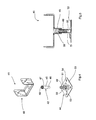
- Fig. 1 shows an exploded view of a support device 1 having an anchoring member 2 that may be used to anchor the support device 1.
- the anchoring member comprises a cylindrical member 3 having a first end 4 intended to be anchored in or to an anchoring base and a second end 5 that is adapted to be attached to a base member 6.
- the base member 6 comprises a support part 7 having a through-going opening 8 adapted to receive the second end 5 of the anchoring member 2.
- the diameter of the opening 8 may be equal to or larger than the diameter of the second end 5 of the anchoring member 2.
- the base member 6 may be provided with a first support member 9 and a second support member 10 providing a vertical support and fastening means 11 for a building structure (not shown), which the support device 1 is intended to support.
- the base member 6 and the vertical support members 9, 10 may be provided as a single sheet of metal, which is bent into a U-shaped form, as shown in Figs. 1-3 .
- the base member 6 and the support members 9, 10 may be provided with a depression 15 in the first surface 14 of the base member 6, which extends from the first surface 14 to the inner surface area of the support members 9,10.
- the depression 15 has a corresponding protrusion 16 running along the underside of the support part 7 and the outer surface of the vertical support members 9, 10.
- the depression 15 and the protrusion 16 contribute to the strength of the base member 6 so as to reduce the risk that the vertical support members 9, 10 may be buckled along the bends 12, 13 at a different angle than the support member 7.
- Fig. 2 shows the support member 1 of Fig. 1 with the second end 5 of the anchoring member 2 having been inserted into the through-going opening 8 of the base member 6.
- a first area 17 of the second end 5 has been deformed to increase the diameter of the first area 17 so that the first area 17 presses against the first surface 14 or the inner periphery of the through-going opening 8.
- a number of radial depressions 18 have been cut/pressed into the anchoring member 2. These depressions reduce the risk that the anchoring member 2 is pulled from an anchoring base (not shown) formed around the first end 4 of the anchoring member.
- Fig. 3 shows a sectional view of the support member 1 of Fig. 3 taken along axis III-III.
- the second end 5 of the anchoring member 2 has a first area 17 that is deformed so that the diameter of the first area 17 is larger than the through-going opening 8 of the support part 7.
- the first area 17 is pressed against the first surface 14 of the support part 7 while a second area 19 of the second end 5 has been deformed to press against a second surface 20 of the support part 7.
- the first area 17 and the second area 19 press tightly against the support part 7 and ensure that the support part 7 is fixed in its position relative to the anchoring member 2.
- Fig. 4 shows an alternative embodiment of a support device 41 of the present invention, where the support device has a base member 43 and a first anchoring member 42 and a second anchoring member 44.
- the coupling of the first anchoring member 42 and the base member 43 is similar to that shown between the anchoring member 2 and the base member 6 of Figs. 1 - 3 and will not be described in relation to Figs. 4 or 5 .
- the first anchoring member 42 has a first cylindrical part 45 having a first end 46 intended to couple with the second anchoring member 44 and a second end 47 that couples to the base member 43.
- the first cylindrical part 45 has an inner surface 48 provided with a helical thread (not shown), which mates with a helical thread 49 provided on the outer surface 50 of the second cylindrical part 51 of the second anchoring member 44.
- the first cylindrical part 45 can be rotated relative to the second cylindrical part 51 to fix the two parts 45, 51 together and to adjust the distance between the second end 46 of the first cylindrical part 45 and a first end 52 of the second cylindrical part 51.
- the first cylindrical part 45 is adapted to surround the second cylindrical part 51, but in other embodiments of the present invention, the opposite may be the preferred solution.
- the first end 52 of the second cylindrical part 51 is provided with a support base plate 53, which is intended to be attached to an anchoring base (not shown) using the attachment means 54, in this embodiment in the form of through-going openings that allow screws, bolts, nails, etc. to be used to fasten the base plate 53 to the anchoring base.
- the strength of the coupling between the first cylindrical part 45 and the second cylindrical part 51 may be increased by having the parts overlap at such a degree that the first cylindrical part 45 and the second cylindrical part 51 may remain in a substantially parallel position relative to each other during use.
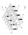
- Fig. 6 shows a building construction 60, where a number of support members 1, 41 as shown in the previous Figs. are used to hold a number of horizontal beams 61, 62, 63.
- the support members 1, as shown in Fig. 1 - 3 are used in as the peripheral support members and are anchored in or to anchoring bases 64 that may be concrete pillars or similar suitable anchoring bases.
- the centre beam 62 is supported by anchoring members 41, as shown in Figs. 4 and 5 , and is attached to the surface of the central anchoring base 65.
- a number of orthogonal beams 66 are positioned and are supported by the horizontal beams 61, 62, 63.
Landscapes
- Engineering & Computer Science (AREA)
- Architecture (AREA)
- Civil Engineering (AREA)
- Structural Engineering (AREA)
- Physics & Mathematics (AREA)
- Electromagnetism (AREA)
- Forms Removed On Construction Sites Or Auxiliary Members Thereof (AREA)
- Joining Of Building Structures In Genera (AREA)
Applications Claiming Priority (1)
| Application Number | Priority Date | Filing Date | Title |
|---|---|---|---|
| GBGB1118045.2A GB201118045D0 (en) | 2011-10-19 | 2011-10-19 | Support device |
Publications (2)
| Publication Number | Publication Date |
|---|---|
| EP2584122A2 true EP2584122A2 (de) | 2013-04-24 |
| EP2584122A3 EP2584122A3 (de) | 2018-01-31 |
Family
ID=45219941
Family Applications (1)
| Application Number | Title | Priority Date | Filing Date |
|---|---|---|---|
| EP12189342.4A Withdrawn EP2584122A3 (de) | 2011-10-19 | 2012-10-19 | Tragvorrichtung |
Country Status (2)
| Country | Link |
|---|---|
| EP (1) | EP2584122A3 (de) |
| GB (1) | GB201118045D0 (de) |
Cited By (2)
| Publication number | Priority date | Publication date | Assignee | Title |
|---|---|---|---|---|
| EP2801682A1 (de) * | 2013-05-07 | 2014-11-12 | Vinzenz Harrer GmbH | Stützenfuß |
| AT516460A1 (de) * | 2014-10-15 | 2016-05-15 | Vh Holding Gmbh | Stützenfuß |
Family Cites Families (4)
| Publication number | Priority date | Publication date | Assignee | Title |
|---|---|---|---|---|
| US5456441A (en) * | 1993-01-11 | 1995-10-10 | United Steel Products Company | Adjustable post base |
| JP3850708B2 (ja) * | 2001-10-23 | 2006-11-29 | 朝日ウッドテック株式会社 | 床板支持装置 |
| US20040163334A1 (en) * | 2003-02-24 | 2004-08-26 | Carlson Bruce Kenneth Oscar | Adjustable beam support |
| JP2007231596A (ja) * | 2006-02-28 | 2007-09-13 | Sumitomo Forestry Co Ltd | 柱脚固定具、柱脚固定構造及び柱脚固定方法 |
-
2011
- 2011-10-19 GB GBGB1118045.2A patent/GB201118045D0/en not_active Ceased
-
2012
- 2012-10-19 EP EP12189342.4A patent/EP2584122A3/de not_active Withdrawn
Cited By (3)
| Publication number | Priority date | Publication date | Assignee | Title |
|---|---|---|---|---|
| EP2801682A1 (de) * | 2013-05-07 | 2014-11-12 | Vinzenz Harrer GmbH | Stützenfuß |
| AT516460A1 (de) * | 2014-10-15 | 2016-05-15 | Vh Holding Gmbh | Stützenfuß |
| AT516460B1 (de) * | 2014-10-15 | 2024-04-15 | Vh Holding Gmbh | Stützenfuß |
Also Published As
| Publication number | Publication date |
|---|---|
| GB201118045D0 (en) | 2011-11-30 |
| EP2584122A3 (de) | 2018-01-31 |
Similar Documents
| Publication | Publication Date | Title |
|---|---|---|
| US8347571B2 (en) | Structural column with footing stilt | |
| US8281541B2 (en) | Hold down connector | |
| AU728413B2 (en) | Holdown connector with concave seat | |
| US5456441A (en) | Adjustable post base | |
| US20090173019A1 (en) | Rotating concentric holdown | |
| US11072940B2 (en) | Embedded post base | |
| EP3135834A1 (de) | Momentresistenter kniestockverbinder | |
| US20120192507A1 (en) | Ground Anchor with Adjustable Positioning Member | |
| US11821199B2 (en) | Girder tie | |
| US11891825B2 (en) | Apparatus for supporting overhead structure | |
| US8511010B2 (en) | Integral catwalk support | |
| AU2023274184B2 (en) | Column shoe manufactured from one piece of sheet metal | |
| JP2008281083A (ja) | 配管用支持金具 | |
| JP3609083B1 (ja) | 建屋基礎の施工法及び建屋基礎の施工用ジョイント盤 | |
| US20110133146A1 (en) | Balustrade | |
| JP7674286B2 (ja) | 仮囲いの転倒防止装置 | |
| KR102763540B1 (ko) | 공동주택의 석재마감재용 더브테일 체결장치 | |
| JP2009209626A (ja) | 被固定部材の据付け面への締結固定構造 | |
| JP2016069883A (ja) | 支圧板付き折曲げ加工鉄筋 | |
| CA2939792C (en) | Moment resisting kneewall connector | |
| JP4677390B2 (ja) | サポートパイプの支持装置 | |
| JP7565121B1 (ja) | 連結金具セット、及び連結方法 | |
| WO2020128592A1 (en) | Clip-on securing system and fastening component therefor | |
| JP2009144348A (ja) | 杭と上部構造物の支持構造 | |
| JP3125895U (ja) | 島台の支持構造 |
Legal Events
| Date | Code | Title | Description |
|---|---|---|---|
| PUAI | Public reference made under article 153(3) epc to a published international application that has entered the european phase |
Free format text: ORIGINAL CODE: 0009012 |
|
| AK | Designated contracting states |
Kind code of ref document: A2 Designated state(s): AL AT BE BG CH CY CZ DE DK EE ES FI FR GB GR HR HU IE IS IT LI LT LU LV MC MK MT NL NO PL PT RO RS SE SI SK SM TR |
|
| AX | Request for extension of the european patent |
Extension state: BA ME |
|
| PUAL | Search report despatched |
Free format text: ORIGINAL CODE: 0009013 |
|
| AK | Designated contracting states |
Kind code of ref document: A3 Designated state(s): AL AT BE BG CH CY CZ DE DK EE ES FI FR GB GR HR HU IE IS IT LI LT LU LV MC MK MT NL NO PL PT RO RS SE SI SK SM TR |
|
| AX | Request for extension of the european patent |
Extension state: BA ME |
|
| RIC1 | Information provided on ipc code assigned before grant |
Ipc: E04H 12/22 20060101AFI20171222BHEP Ipc: E04B 1/00 20060101ALI20171222BHEP Ipc: E04B 1/26 20060101ALI20171222BHEP |
|
| STAA | Information on the status of an ep patent application or granted ep patent |
Free format text: STATUS: THE APPLICATION IS DEEMED TO BE WITHDRAWN |
|
| 18D | Application deemed to be withdrawn |
Effective date: 20180801 |