EP2584125A2 - Cadenas - Google Patents
Cadenas Download PDFInfo
- Publication number
- EP2584125A2 EP2584125A2 EP12187872.2A EP12187872A EP2584125A2 EP 2584125 A2 EP2584125 A2 EP 2584125A2 EP 12187872 A EP12187872 A EP 12187872A EP 2584125 A2 EP2584125 A2 EP 2584125A2
- Authority
- EP
- European Patent Office
- Prior art keywords
- locking
- lock
- housing
- profile
- opening
- Prior art date
- Legal status (The legal status is an assumption and is not a legal conclusion. Google has not performed a legal analysis and makes no representation as to the accuracy of the status listed.)
- Withdrawn
Links
- 238000003780 insertion Methods 0.000 claims abstract description 21
- 230000037431 insertion Effects 0.000 claims abstract description 21
- 238000006073 displacement reaction Methods 0.000 description 2
- 210000003746 feather Anatomy 0.000 description 1
- 239000002184 metal Substances 0.000 description 1
- 230000036316 preload Effects 0.000 description 1
- IHQKEDIOMGYHEB-UHFFFAOYSA-M sodium dimethylarsinate Chemical class [Na+].C[As](C)([O-])=O IHQKEDIOMGYHEB-UHFFFAOYSA-M 0.000 description 1
Images




Classifications
-
- E—FIXED CONSTRUCTIONS
- E05—LOCKS; KEYS; WINDOW OR DOOR FITTINGS; SAFES
- E05B—LOCKS; ACCESSORIES THEREFOR; HANDCUFFS
- E05B67/00—Padlocks; Details thereof
- E05B67/02—Cases
-
- E—FIXED CONSTRUCTIONS
- E05—LOCKS; KEYS; WINDOW OR DOOR FITTINGS; SAFES
- E05B—LOCKS; ACCESSORIES THEREFOR; HANDCUFFS
- E05B67/00—Padlocks; Details thereof
- E05B67/06—Shackles; Arrangement of the shackle
- E05B67/22—Padlocks with sliding shackles, with or without rotary or pivotal movement
- E05B67/24—Padlocks with sliding shackles, with or without rotary or pivotal movement with built- in cylinder locks
Definitions
- the invention relates to a padlock with a lock housing and a U-shaped lock bracket, wherein the U-legs of the lock bracket having a bearing end and a locking end, the bearing end movable, in particular rotatably inserted in a bearing opening of the lock housing and the locking end with a locking opening to Inserting the locking end associated latch member in the lock housing cooperates such that in a locking position in which the locking member engages in a locking recess of the locking end, both lock bow ends are fixed to the lock housing, and in a release position in which the locking member does not engage in the locking recess, the Locking end of the lock housing is solvable.
- From the EP 1460 212 B1 is a padlock with a U-shaped lock bow known.
- a U-leg forms a bearing end, which is inserted in a bearing opening of the lock housing.
- the aligned parallel to the bearing end locking end of the lock bracket is inserted in a locking opening and is held there by a locking member in a locking position. If the locking member is pivoted out of a locking recess, the bearing end and at the same time the locking end can be pulled out of their associated openings of the lock housing. In this case, the locking end completely detached from the lock housing, so that the lock bracket and the bearing end can be pivoted.
- the WO 97/01012 A1 describes a padlock with an L-shaped lock handle.
- the bearing end of the lock bracket is axially and rotationally fixed to the Lock housing connected.
- a second lock housing part can be pushed in front of the free end of the locking end of the L-shaped lock bracket.
- a padlock in which an L-shaped lock bracket is materially connected to the lock housing, and in which an axially displaceable bolt is provided to close an opening of the lock bracket, which shows DE 297 22 017 U1 ,
- the DE 10 35 008 B describes a padlock with a U-shaped lock bracket, the locking end is released in the release position of the lock housing.
- the lock bracket can be pivoted in the release position to a bearing end.
- the EP 2 267 256 A2 describes a padlock with a lock housing in which a slider is located, which has an L-shaped lock bracket, which can be brought by displacing the slider in a locking position.
- the invention has for its object to develop a generic padlock locking technology.
- the outer wall of the lock housing which characterizes the outline contour of the lock housing, is formed by the outer wall of two mutually displaceable in the direction of extension of the U-legs of the lock bracket housing parts.
- a second housing part has the locking opening.
- the bearing end of the lock bracket is axially fixed in the bearing opening. It is pivotable about the axis of the U-leg.
- the two housing parts are pushed together.
- the two castle parts are shifted from each other.
- the latch member must be brought into a release position.
- the locking member is preferably formed by the closing member of a plug-in in a profile opening of the second housing part profile cylinder.
- the two housing parts are coupled to one another via a tongue and groove connection. It is preferably an undercut tongue and groove connection.
- the groove may, for example, have a C-shaped cross-section.
- the spring may have a shape-adapted, approximately mushroom-shaped cross-section.
- a retaining spring may be provided which temporarily holds the two housing parts in the collapsed position. This can be done by a snap or frictional.
- the spring may be a leaf spring with a latching tongue. It is further provided that the two housing parts can be moved against each other against a stop position and apart. In a stop position, the second housing part can strike against a housing wall of the first housing part. In the open position another stop is provided. This may be formed by the head portion of a profile cylinder mounting screw.
- the head of the profile cylinder mounting screw can slide along in a groove of the first housing part, wherein the groove end forms the stop.
- the profile lock cylinder is fixed by means of this screw in the second housing part, which has a profile opening into which a half-profile cylinder can be inserted.
- a padlock in which a half-closing cylinder can be inserted, is from the above-mentioned EP 1 460 212 B1 previously known.
- the locking member is formed by a cam of the lock cylinder. In the key withdrawal position, the locking member is approximately in a 30 ° position, based on the profile section of the lock cylinder. For this reason, the profile section of the insertion, in which the profile lock cylinder is inserted, extends obliquely to the lock bracket level. This results in a voluminous shape of the lock housing.
- the locking opening is diametrically associated with the profile section of the profile-locking cylinder.
- the locking opening is diametrically opposite the profile section of the profile cylinder associated section of the profile opening.
- a profile lock cylinder the closing member in the key withdrawal position diametrically opposite the profile section of the profile closing cylinder.
- the profile section of the insertion opening for the profile lock cylinder can lie in the same plane into which the lock bracket is located. It is particularly advantageous if a profile locking cylinder is used, in which the angular position of the closing member in the key withdrawal position is adjustable. The angular position of the closing member can then be brought into the twelve o'clock position.
- the padlock shown in the drawings has essentially two housing parts 1 and 2, which are made of metal.
- the two housing parts each form sections of the outer wall of the entire lock housing.
- the first housing part 1 has a lock outer wall 1 ', which merges flush with the outer wall 2' of the second housing part 2.
- the two housing parts 1, 2 each form end faces 1 ", 2" which are opposite the lock bracket 3. In the closed position of the padlock, the two end faces 1 ", 2" are flush with one another.
- the first housing part 1 forms a slide-in channel 25 into which an insertion strip 26 of the second housing part 2 can be inserted.
- the insertion channel 25 is flanked by two nearly parallel webs, which have a different length and which forms springs 13 at their ends.
- the two springs 13 have a mushroom-like shape in cross section.
- the first housing part 1 forms a bearing opening 6, in which the bearing end 4 of the lock bracket 3 is inserted.
- the bearing end 4 is there by means of a screw 22 which is screwed into the end face of the bearing end 4, axially fixed, but rotatably tied.
- a sleeve 31 is provided, through which the shaft of the screw 22 engages.
- the second housing part 2 has a profile opening 10 for insertion of a profile locking cylinder 11.
- the profile section 19 of the profile opening 10 lies in the same plane in which the mutually parallel U-legs of the U-shaped lock bracket 3 are located.
- the profile section 19 protrudes into an insertion strip 26, which is displaceable within the insertion channel 25.
- the insertion strip 26 is flanked on both sides by grooves 12, which have an undercut cross-sectional contour.
- the cross section of the grooves 12 corresponds to the cross section of the springs 13, so that the springs 13 can be pushed into the grooves 12.
- a commercial semi-profile closing cylinder 11 can be inserted.
- This profile lock cylinder 11 has a profile section 18 which fits into the profile section 19 of the opening 10.
- the profile lock cylinder 11 has a cylinder core with a keyway 21, in which the cam of a flat key 20 can be pushed.
- the locking member 8 With the correct key 20, the locking member 8 can be pivoted from a locking position in which it is diametrically opposed to the profile section 18.
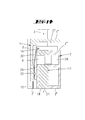
- the locking position is in the Fig. 4 shown. In this position, the closing member 8 engages in a locking recess 9 of the locking end 5, so that the locking end 5 can not be pulled out of the locking hole 7. Only when by turning the key 20 of the cylinder core and the rotatably coupled with him closing member 8, for example.
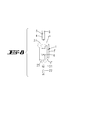
- the curtain lock 10 is shown pivoted release position, wherein the locking member 8 is immersed in a free space 28 of the second housing part 2, the curtain lock reaches its release position in which the locking end 5 can be pulled out of the locking opening 7.
- the two housing parts 1, 2 must be moved against each other, the springs 13 slide into the grooves 12.
- an end face 2 '' 'of the second housing part 2 facing the lock bracket 3 rests against a housing wall 27 of the first housing part 1.
- the housing 27 forms with one of its two broad sides an end face 1 '' ', which points to the lock bracket 3.
- the first housing part 1 has a longitudinal slot in the form of a groove 17.
- the width of the groove 17 corresponds almost with running clearance the diameter of the screw head of a fastening screw 15, with the profile lock cylinder 11 can be tied in the profile opening 10.
- the thread of the fastening screw 15 is screwed into the forend screw of the profile closing cylinder 11.
- the head of the fastening screw 15 protrudes slightly beyond the broad side of the insertion strip 26 and thus into the groove 17.
- One end 16 of the groove 17 forms a stop against which the head of the fastening screw 15 enters the position in which the two housing parts 1, 2 maximally far apart are pushed.
- the fastening screw 15 thus forms together with the end 16 of the groove 17 a Aufillerschiebbegrenzungsanschlag. If the screw 15 is unscrewed, for which purpose an opening 24 is provided in the region of the end of the groove 17, the two housing parts 1, 2 can be separated from one another. When unscrewed fastening screw 15 and the profile cylinder 11 can be pulled out of its associated opening 10 and, for example, be replaced by another. In the closed position of the lock is the fixing screw 15 inaccessible because it lies in the other end portion of the groove 17.
- the displacement movement of the two housing parts 1, 2 is also stop limit in the opposite direction.
- the end face 2 '' 'of the housing 2 occurs against the housing wall 27th
- Both the groove 17 of the housing part 1 and a niche 29 adjacent to the groove 17 of the housing part 2 extend parallel to the springs 13, ie in the direction of displacement of the two lock housing parts 1, 2, which corresponds to the extension direction of the U-legs of the lock bracket 3.
- a leaf spring 30 is arranged in the niche. It is fastened there by means of a screw 23, as shown in FIG. 23.
- An alternative attachment shows the Fig. 14 , There, the leaf spring is held with a umbörtelten pin 32 which passes through an opening of the leaf spring.
- the leaf spring 30 has a protruding into the insertion channel 25 section in the form of a tongue 14.
- This tongue 14 is spring-loaded on the wall of the second housing part 2 at. It forms a frictional shear resistance.
- the latching tongue 14 can engage in a recess 29 which lies at the level of the latch member 8. According to the spring 30 and its locking action, the two housing parts 1, 2 can be pulled apart only after deliberately twisting the lock cylinder in the release position, wherein when pulling the two housing parts 1, 2, the locking end 5 is pulled out of the locking hole 7 of the second housing part.
- the Fig. 14 shows the only partially nested lock housing parts 1, 2, wherein the end face 2 '''of the lock housing 2 in front of the tongue 14 is located. If the two housing parts 1, 2 are pushed further into one another, an obliquely running section of the tongue 14 runs on the edge of the end face 2 '", so that the spring 30 bends and tensions. In the in Fig. 11 shown fully inserted position is the tongue 14 with spring preload on the wall of the second housing part 2.
- the lock cylinder 11 has the property that its closing member 8, although rotatably connected to the cylinder core. However, the rotational strength can be canceled by releasing a lock to change the angular position of the closing member 8 relative to the cylinder core in the key withdrawal position.
- the closing member 8 can thus be brought into a twelve o'clock position, so that the closing member 8 in the key withdrawal position the profile section 18 of the profile closing cylinder 11 is opposite.
Landscapes
- Control Of Vending Devices And Auxiliary Devices For Vending Devices (AREA)
- Lock And Its Accessories (AREA)
Applications Claiming Priority (1)
| Application Number | Priority Date | Filing Date | Title |
|---|---|---|---|
| DE102011054705A DE102011054705A1 (de) | 2011-10-21 | 2011-10-21 | Vorhangschloss |
Publications (2)
| Publication Number | Publication Date |
|---|---|
| EP2584125A2 true EP2584125A2 (fr) | 2013-04-24 |
| EP2584125A3 EP2584125A3 (fr) | 2018-04-11 |
Family
ID=47002744
Family Applications (1)
| Application Number | Title | Priority Date | Filing Date |
|---|---|---|---|
| EP12187872.2A Withdrawn EP2584125A3 (fr) | 2011-10-21 | 2012-10-10 | Cadenas |
Country Status (2)
| Country | Link |
|---|---|
| EP (1) | EP2584125A3 (fr) |
| DE (1) | DE102011054705A1 (fr) |
Cited By (1)
| Publication number | Priority date | Publication date | Assignee | Title |
|---|---|---|---|---|
| CN116427794A (zh) * | 2023-04-10 | 2023-07-14 | 浙江中立集团有限公司 | 一种伸缩u形锁 |
Citations (5)
| Publication number | Priority date | Publication date | Assignee | Title |
|---|---|---|---|---|
| DE1035008B (de) | 1952-01-10 | 1958-07-24 | Willi Rojan | Sicherheitsschloss |
| WO1997001012A1 (fr) | 1995-06-23 | 1997-01-09 | Total Security (Aust) Pty. Ltd. | Cadenas |
| DE29722017U1 (de) | 1997-12-11 | 1998-02-19 | Shieh, Jin-Ren, Taichung | Schloß für eine Scheibenbremse eines Motorrades |
| EP1460212B1 (fr) | 2003-03-05 | 2010-05-05 | ISEO Deutschland GmbH | Cadenas |
| EP2267256A2 (fr) | 2009-06-23 | 2010-12-29 | ABUS August Bremicker Söhne KG | Cadenas |
Family Cites Families (4)
| Publication number | Priority date | Publication date | Assignee | Title |
|---|---|---|---|---|
| US2185899A (en) * | 1937-05-01 | 1940-01-02 | Charles H Nehls | Padlock |
| US7021092B2 (en) * | 2003-05-16 | 2006-04-04 | Stanton Concepts Inc. | Multiple function lock |
| US7434426B2 (en) * | 2003-05-16 | 2008-10-14 | Stanton Concepts Inc. | Multiple function lock |
| FR2920806B1 (fr) * | 2007-09-06 | 2010-11-12 | Vachette Sa | Cadenas. |
-
2011
- 2011-10-21 DE DE102011054705A patent/DE102011054705A1/de not_active Withdrawn
-
2012
- 2012-10-10 EP EP12187872.2A patent/EP2584125A3/fr not_active Withdrawn
Patent Citations (5)
| Publication number | Priority date | Publication date | Assignee | Title |
|---|---|---|---|---|
| DE1035008B (de) | 1952-01-10 | 1958-07-24 | Willi Rojan | Sicherheitsschloss |
| WO1997001012A1 (fr) | 1995-06-23 | 1997-01-09 | Total Security (Aust) Pty. Ltd. | Cadenas |
| DE29722017U1 (de) | 1997-12-11 | 1998-02-19 | Shieh, Jin-Ren, Taichung | Schloß für eine Scheibenbremse eines Motorrades |
| EP1460212B1 (fr) | 2003-03-05 | 2010-05-05 | ISEO Deutschland GmbH | Cadenas |
| EP2267256A2 (fr) | 2009-06-23 | 2010-12-29 | ABUS August Bremicker Söhne KG | Cadenas |
Cited By (1)
| Publication number | Priority date | Publication date | Assignee | Title |
|---|---|---|---|---|
| CN116427794A (zh) * | 2023-04-10 | 2023-07-14 | 浙江中立集团有限公司 | 一种伸缩u形锁 |
Also Published As
| Publication number | Publication date |
|---|---|
| DE102011054705A1 (de) | 2013-04-25 |
| EP2584125A3 (fr) | 2018-04-11 |
Similar Documents
| Publication | Publication Date | Title |
|---|---|---|
| DE69806907T2 (de) | Verschlussvorrichtung für eine tür | |
| EP2862991B1 (fr) | Dispositif de verrouillage | |
| EP2055867A1 (fr) | Poignée dotée d'une garniture de fermeture | |
| EP2112304B1 (fr) | Insert de serrure pour une serrure de porte en verre | |
| EP1817983A1 (fr) | Dispositif pour influencer le mouvement des parties de meuble l'une par rapport à l'autre et une glissière pour tiroirs, ainsi qu'un procédé de fabrication d'un tel dispositif | |
| DE202015105127U1 (de) | Fenster- und/oder Türsicherung | |
| EP1297232B1 (fr) | Fermeture de portiere de vehicule automobile | |
| EP2172606B2 (fr) | Dispositif de poignée | |
| EP2584125A2 (fr) | Cadenas | |
| DE102009026093A1 (de) | Einsteckschloss mit variablem Dornmaß und variabler Entfernung | |
| EP3194690B1 (fr) | Ferrure pour fenêtres, portes ou similaires | |
| EP4045744B1 (fr) | Ensemble ferrure | |
| EP2503080A2 (fr) | Abattant à borne à ressort | |
| DE10329414B4 (de) | Schließvorrichtung | |
| DE102022120478A1 (de) | Betätigungshandhabe | |
| EP2532816B1 (fr) | Dispositif d'entraînement pour une armature de bielle | |
| EP3670800B1 (fr) | Serrure pourvue de dispositif de crémone et procédé d'ajustement d'une tige de crémone | |
| EP4074931A1 (fr) | Ferrure dotée d'un crochet d'encliquetage pouvant être bloqué par coulissement longitudinal | |
| DE102004060477B4 (de) | Schließzylinder | |
| EP1577465B1 (fr) | Élément de verrouillage avec fixation pour élément d'actionnement | |
| EP3266960A1 (fr) | Système comprenant un châssis dormant destiné à loger un cadre de vantail | |
| EP3741935B1 (fr) | Verrou d'aiguille à articulation | |
| EP1455041B1 (fr) | Serrure à plusieurs pênes avec une tringle et un dispositif de retenue. | |
| DE202011005241U1 (de) | Stangenführung | |
| DE202010010675U1 (de) | Mitnahmevorrichtung für Arretierelement eines Schlosses |
Legal Events
| Date | Code | Title | Description |
|---|---|---|---|
| PUAI | Public reference made under article 153(3) epc to a published international application that has entered the european phase |
Free format text: ORIGINAL CODE: 0009012 |
|
| AK | Designated contracting states |
Kind code of ref document: A2 Designated state(s): AL AT BE BG CH CY CZ DE DK EE ES FI FR GB GR HR HU IE IS IT LI LT LU LV MC MK MT NL NO PL PT RO RS SE SI SK SM TR |
|
| AX | Request for extension of the european patent |
Extension state: BA ME |
|
| RIC1 | Information provided on ipc code assigned before grant |
Ipc: E05B 67/02 20060101ALI20171201BHEP Ipc: E05B 67/24 20060101AFI20171201BHEP |
|
| RAP1 | Party data changed (applicant data changed or rights of an application transferred) |
Owner name: STEEL & STYLE LIMITED |
|
| PUAL | Search report despatched |
Free format text: ORIGINAL CODE: 0009013 |
|
| AK | Designated contracting states |
Kind code of ref document: A3 Designated state(s): AL AT BE BG CH CY CZ DE DK EE ES FI FR GB GR HR HU IE IS IT LI LT LU LV MC MK MT NL NO PL PT RO RS SE SI SK SM TR |
|
| AX | Request for extension of the european patent |
Extension state: BA ME |
|
| RIC1 | Information provided on ipc code assigned before grant |
Ipc: E05B 67/24 20060101AFI20180307BHEP Ipc: E05B 67/02 20060101ALI20180307BHEP |
|
| STAA | Information on the status of an ep patent application or granted ep patent |
Free format text: STATUS: THE APPLICATION IS DEEMED TO BE WITHDRAWN |
|
| 18D | Application deemed to be withdrawn |
Effective date: 20181012 |