EP2584143B1 - Komponente eines Gasturbinenantriebs - Google Patents
Komponente eines Gasturbinenantriebs Download PDFInfo
- Publication number
- EP2584143B1 EP2584143B1 EP13151206.3A EP13151206A EP2584143B1 EP 2584143 B1 EP2584143 B1 EP 2584143B1 EP 13151206 A EP13151206 A EP 13151206A EP 2584143 B1 EP2584143 B1 EP 2584143B1
- Authority
- EP
- European Patent Office
- Prior art keywords
- exemplary
- trailing edge
- stacked
- casting
- component
- Prior art date
- Legal status (The legal status is an assumption and is not a legal conclusion. Google has not performed a legal analysis and makes no representation as to the accuracy of the status listed.)
- Not-in-force
Links
Images


Classifications
-
- F—MECHANICAL ENGINEERING; LIGHTING; HEATING; WEAPONS; BLASTING
- F01—MACHINES OR ENGINES IN GENERAL; ENGINE PLANTS IN GENERAL; STEAM ENGINES
- F01D—NON-POSITIVE DISPLACEMENT MACHINES OR ENGINES, e.g. STEAM TURBINES
- F01D5/00—Blades; Blade-carrying members; Heating, heat-insulating, cooling or antivibration means on the blades or the members
- F01D5/12—Blades
- F01D5/14—Form or construction
- F01D5/18—Hollow blades, i.e. blades with cooling or heating channels or cavities; Heating, heat-insulating or cooling means on blades
- F01D5/187—Convection cooling
-
- B—PERFORMING OPERATIONS; TRANSPORTING
- B22—CASTING; POWDER METALLURGY
- B22C—FOUNDRY MOULDING
- B22C7/00—Patterns; Manufacture thereof so far as not provided for in other classes
- B22C7/02—Lost patterns
-
- B—PERFORMING OPERATIONS; TRANSPORTING
- B22—CASTING; POWDER METALLURGY
- B22C—FOUNDRY MOULDING
- B22C9/00—Moulds or cores; Moulding processes
- B22C9/02—Sand moulds or like moulds for shaped castings
- B22C9/04—Use of lost patterns
- B22C9/043—Removing the consumable pattern
-
- B—PERFORMING OPERATIONS; TRANSPORTING
- B22—CASTING; POWDER METALLURGY
- B22C—FOUNDRY MOULDING
- B22C9/00—Moulds or cores; Moulding processes
- B22C9/10—Cores; Manufacture or installation of cores
- B22C9/103—Multipart cores
-
- F—MECHANICAL ENGINEERING; LIGHTING; HEATING; WEAPONS; BLASTING
- F01—MACHINES OR ENGINES IN GENERAL; ENGINE PLANTS IN GENERAL; STEAM ENGINES
- F01D—NON-POSITIVE DISPLACEMENT MACHINES OR ENGINES, e.g. STEAM TURBINES
- F01D5/00—Blades; Blade-carrying members; Heating, heat-insulating, cooling or antivibration means on the blades or the members
- F01D5/02—Blade-carrying members, e.g. rotors
- F01D5/08—Heating, heat-insulating or cooling means
- F01D5/081—Cooling fluid being directed on the side of the rotor disc or at the roots of the blades
-
- F—MECHANICAL ENGINEERING; LIGHTING; HEATING; WEAPONS; BLASTING
- F01—MACHINES OR ENGINES IN GENERAL; ENGINE PLANTS IN GENERAL; STEAM ENGINES
- F01D—NON-POSITIVE DISPLACEMENT MACHINES OR ENGINES, e.g. STEAM TURBINES
- F01D9/00—Stators
- F01D9/02—Nozzles; Nozzle boxes; Stator blades; Guide conduits, e.g. individual nozzles
- F01D9/04—Nozzles; Nozzle boxes; Stator blades; Guide conduits, e.g. individual nozzles forming ring or sector
- F01D9/041—Nozzles; Nozzle boxes; Stator blades; Guide conduits, e.g. individual nozzles forming ring or sector using blades
-
- F—MECHANICAL ENGINEERING; LIGHTING; HEATING; WEAPONS; BLASTING
- F05—INDEXING SCHEMES RELATING TO ENGINES OR PUMPS IN VARIOUS SUBCLASSES OF CLASSES F01-F04
- F05D—INDEXING SCHEME FOR ASPECTS RELATING TO NON-POSITIVE-DISPLACEMENT MACHINES OR ENGINES, GAS-TURBINES OR JET-PROPULSION PLANTS
- F05D2230/00—Manufacture
- F05D2230/20—Manufacture essentially without removing material
- F05D2230/21—Manufacture essentially without removing material by casting
- F05D2230/211—Manufacture essentially without removing material by casting by precision casting, e.g. microfusing or investment casting
-
- F—MECHANICAL ENGINEERING; LIGHTING; HEATING; WEAPONS; BLASTING
- F05—INDEXING SCHEMES RELATING TO ENGINES OR PUMPS IN VARIOUS SUBCLASSES OF CLASSES F01-F04
- F05D—INDEXING SCHEME FOR ASPECTS RELATING TO NON-POSITIVE-DISPLACEMENT MACHINES OR ENGINES, GAS-TURBINES OR JET-PROPULSION PLANTS
- F05D2240/00—Components
- F05D2240/10—Stators
- F05D2240/12—Fluid guiding means, e.g. vanes
- F05D2240/122—Fluid guiding means, e.g. vanes related to the trailing edge of a stator vane
-
- F—MECHANICAL ENGINEERING; LIGHTING; HEATING; WEAPONS; BLASTING
- F05—INDEXING SCHEMES RELATING TO ENGINES OR PUMPS IN VARIOUS SUBCLASSES OF CLASSES F01-F04
- F05D—INDEXING SCHEME FOR ASPECTS RELATING TO NON-POSITIVE-DISPLACEMENT MACHINES OR ENGINES, GAS-TURBINES OR JET-PROPULSION PLANTS
- F05D2240/00—Components
- F05D2240/20—Rotors
- F05D2240/30—Characteristics of rotor blades, i.e. of any element transforming dynamic fluid energy to or from rotational energy and being attached to a rotor
- F05D2240/304—Characteristics of rotor blades, i.e. of any element transforming dynamic fluid energy to or from rotational energy and being attached to a rotor related to the trailing edge of a rotor blade
-
- F—MECHANICAL ENGINEERING; LIGHTING; HEATING; WEAPONS; BLASTING
- F05—INDEXING SCHEMES RELATING TO ENGINES OR PUMPS IN VARIOUS SUBCLASSES OF CLASSES F01-F04
- F05D—INDEXING SCHEME FOR ASPECTS RELATING TO NON-POSITIVE-DISPLACEMENT MACHINES OR ENGINES, GAS-TURBINES OR JET-PROPULSION PLANTS
- F05D2260/00—Function
- F05D2260/20—Heat transfer, e.g. cooling
- F05D2260/221—Improvement of heat transfer
- F05D2260/2212—Improvement of heat transfer by creating turbulence
-
- F—MECHANICAL ENGINEERING; LIGHTING; HEATING; WEAPONS; BLASTING
- F05—INDEXING SCHEMES RELATING TO ENGINES OR PUMPS IN VARIOUS SUBCLASSES OF CLASSES F01-F04
- F05D—INDEXING SCHEME FOR ASPECTS RELATING TO NON-POSITIVE-DISPLACEMENT MACHINES OR ENGINES, GAS-TURBINES OR JET-PROPULSION PLANTS
- F05D2260/00—Function
- F05D2260/20—Heat transfer, e.g. cooling
- F05D2260/221—Improvement of heat transfer
- F05D2260/2214—Improvement of heat transfer by increasing the heat transfer surface
- F05D2260/22141—Improvement of heat transfer by increasing the heat transfer surface using fins or ribs
-
- F—MECHANICAL ENGINEERING; LIGHTING; HEATING; WEAPONS; BLASTING
- F05—INDEXING SCHEMES RELATING TO ENGINES OR PUMPS IN VARIOUS SUBCLASSES OF CLASSES F01-F04
- F05D—INDEXING SCHEME FOR ASPECTS RELATING TO NON-POSITIVE-DISPLACEMENT MACHINES OR ENGINES, GAS-TURBINES OR JET-PROPULSION PLANTS
- F05D2300/00—Materials; Properties thereof
- F05D2300/20—Oxide or non-oxide ceramics
- F05D2300/21—Oxide ceramics
-
- Y—GENERAL TAGGING OF NEW TECHNOLOGICAL DEVELOPMENTS; GENERAL TAGGING OF CROSS-SECTIONAL TECHNOLOGIES SPANNING OVER SEVERAL SECTIONS OF THE IPC; TECHNICAL SUBJECTS COVERED BY FORMER USPC CROSS-REFERENCE ART COLLECTIONS [XRACs] AND DIGESTS
- Y02—TECHNOLOGIES OR APPLICATIONS FOR MITIGATION OR ADAPTATION AGAINST CLIMATE CHANGE
- Y02T—CLIMATE CHANGE MITIGATION TECHNOLOGIES RELATED TO TRANSPORTATION
- Y02T50/00—Aeronautics or air transport
- Y02T50/60—Efficient propulsion technologies, e.g. for aircraft
Definitions
- the disclosure relates to investment casting. More particularly, it relates to the investment casting of superalloy turbine engine components.
- Investment casting is a commonly used technique for forming metallic components having complex geometries, especially hollow components, and is used in the fabrication of superalloy gas turbine engine components.
- the disclosure is described in respect to the production of particular superalloy castings, however it is understood that the disclosure is not so limited.
- Gas turbine engines are widely used in aircraft propulsion, electric power generation, and ship propulsion. In gas turbine engine applications, efficiency is a prime objective. Improved gas turbine engine efficiency can be obtained by operating at higher temperatures, however current operating temperatures in the turbine section exceed the melting points of the superalloy materials used in turbine components. Consequently, it is a general practice to provide air cooling. Cooling is provided by flowing relatively cool air from the compressor section of the engine through passages in the turbine components to be cooled. Such cooling comes with an associated cost in engine efficiency. Consequently, there is a strong desire to provide enhanced specific cooling, maximizing the amount of cooling benefit obtained from a given amount of cooling air. This may be obtained by the use of fine, precisely located, cooling passageway sections.
- the cooling passageway sections may be cast over casting cores.
- Ceramic casting cores may be formed by molding a mixture of ceramic powder and binder material by injecting the mixture into hardened steel dies. After removal from the dies, the green cores are thermally post-processed to remove the binder and fired to sinter the ceramic powder together.
- the trend toward finer cooling features has taxed core manufacturing techniques. The fine features may be difficult to manufacture and/or, once manufactured, may prove fragile.
- Commonly-assigned U.S. Patent Nos. 6,637,500 of Shah et al. , 6,929,054 of Beals et al. , 7,014,424 of Cunha et al. , 7,134,475 of Snyder et al. and U.S. Patent Publication No. 20060239819 of Albert et al.
- WO 03/042503 A1 discloses a prior art gas turbine component as set forth in the preamble of claim 1.
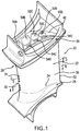
- FIG. 1 shows a gas turbine engine vane 20.
- the vane 20 has an airfoil 22 extending from an inboard end 24 at the outboard surface of a platform (or inner diameter (ID) shroud) 26 to an outboard end 28 at the inboard surface of an outboard (outer diameter or OD) shroud 29.
- the airfoil has a leading edge 30 and a trailing edge 32.
- the airfoil has a suction side/surface 34 and a pressure side/surface 36 extending between the leading edge 30 and the trailing edge 32.
- the exemplary vane 20 is cast from an alloy (e.g., a nickel-based superalloy) and has an internal cooling passageway system.
- the exemplary cooling passageway system has a plurality of inlets.
- the exemplary inlets are along the OD shroud 29, more particularly along the outboard end/surface 42 of the OD shroud 29.
- the exemplary vane has inlets 50A-50D, 52C&52D, and 54B-54D ( FIG. 1 ), discussed further below.
- the exemplary cooling passageway system has a plurality of outlets.
- the exemplary outlets include an outlet 56 ( FIG. 3 ) along the ID surface 57 of the ID shroud 26 and outlets along the airfoil 22.
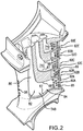
- Exemplary outlets along the airfoil include leading edge outlets 58 and trailing edge outlets 60A-60E ( FIG. 2 ).
- the exemplary trailing edge outlets 60 are formed by respective segments 62A-62E of a trailing edge discharge slot.
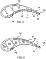
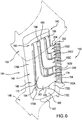
- Each slot segment 62A-62E has a suction side surface 63 and a pressure side surface 64 ( FIGS. 4 &5).
- a plurality of posts 65 may extend between the surfaces 63 and 64. Additionally or alternatively, pedestals (not shown) may extend from either of the surfaces 63 or 64, terminating short of the other.
- Wall sections 66 FIG. 2 ) may separate the respective segments 62A-62E from each other at edges 67 and 68. As is discussed below, the surfaces 63 and 64 and edges 67 and 68 continue upstream along passageways feeding the associated slot segments.
- segments 62A-62E may be differently fed relative to each other (e.g., fed from different inlets or via at least partially separated passageways passing through different portions of the airfoil). In the exemplary embodiment, several differences exist in the feeding of the respective segments 62A-62E.
- the exemplary segments 62A, 62C, and 62E are fed via passageways passing mostly relatively near the pressure side 36 of the airfoil; whereas the segments 62B and 62D are fed by passageways passing relatively closer to the suction side 34.
- the exemplary inlets 50A-50D, 52C&52D, and 54B-54D of FIG. 1 each feed a respective passageway 70A-70D ( FIG. 3 ), 72C&72D, and 74B-74D ( FIG. 2 ).
- the segments 62A, 62C, and 62E are respectively formed as terminal portions of the passageways 74B, 74C, and 74D, respectively, with 60A, 60C, and 60E being the outlets of such passageways.
- the segments 62B and 62D are respectively formed as terminal portions of the passageways 72C and 72D, respectively, with 60B and 60D being the outlets thereof.
- the exemplary passageways 70A-70D merge in an outlet plenum 73 ( FIG. 3 ) in the ID shroud 26 along which the outlet 56 is located.
- Each of the exemplary passageways 72C and 72D and 74B-74D is approximately L-shaped in planform, having an upstream leg 80 extending spanwise inboard from the associated inlet to a junction 82 with a foot 84.
- the foot 84 extends streamwise to the associated outlet and includes the associated slot segment.
- the exemplary passageways 70A-70D are sequentially staggered streamwise relative to each other from upstream to downstream (leading edge toward trailing edge). These passageways 70A-70D are generally centrally positioned between the suction side 34 and pressure side 36.
- the passageways 72C and 72D are shifted relatively toward the suction side 34 (well away from the median of the airfoil section) at least along their legs 80 and upstream portions of their feet 84.
- the passageways 74B-74D are shifted toward the pressure side 36 along their legs 80 and the upstream portions of their feet 84. Upstream of the segments 62A-62E, therefore, the groups of the passageways are staggered/offset from each other between the suction side 34 and pressure side 36.
- This stagger may be overall and may be local.
- An example of the local stagger is: at the OD shroud 29, the passageway 72C is immediately to the suction side of the passageway 70C and the passageway 74C is immediately to the pressure side of the passageway 70C.
- the exemplary passageways 72C&72D and 74B-74D have bends ( FIGS. 4 and 5 ) 86, 87 along the legs 84 upstream of the segments 62A-62E.
- FIG. 6 shows a pattern 140 for casting the vane 20.
- the exemplary pattern comprises a combination 142 of casting cores (core combination) and a pattern material 144 (e.g., wax) in which the core combination is at least partially embedded.
- the pattern material has an external surface generally corresponding to the external surface of the vane 20 (i.e., having an airfoil 146, an ID shroud 148, and an OD shroud 150).
- the core combination 142 has an external surface (complementary to the mating internal surface of the pattern material) generally corresponding to portions of the passageway system (e.g., excluding drilled outlets).
- FIG. 6 shows the combination 142 in solid lines and the pattern material 144 in broken lines.
- the exemplary core combination 142 is formed as the assembly of one or more ceramic cores 160 and one or more metallic cores 162A-162E.
- the metallic casting cores 162A-162E are refractory metal cores (RMCs).
- RMCs are refractory metal based (i.e., having substrates of at least fifty weight percent one or more refractory metals such as molybdenum, tungsten, niobium, or the like, optionally coated).
- Exemplary RMCs are formed of sheet stock and have opposite surfaces/faces 163 and 164 and an edge/perimeter 165.
- the core combination 142 has surfaces overall complementary to at least main surfaces of the passageway network.
- the exemplary ceramic core 160 includes respective trunk portions 170A-170D for casting the passageways, 70A-70D.
- the ceramic core 160 further includes an ID junction 166 for casting the plenum 73 and an ID neck 167 for casting the port 56.
- the RMCs 162A-162E are positioned to cast the passageways respectively associated with the segments 62A-62E.
- the exemplary RMCs thus each include a corresponding leg portion 172 and foot portion 174.
- the RMCs further include first end portions 180 for mating with an OD portion 182 of the ceramic core 160.
- the exemplary RMC foot portions include terminal portions 184 protruding from the pattern material to embed in a shell (not shown) discussed below.
- the exemplary first end portions 180 are bent (e.g., at bends 186) away from adjacent portions of the legs 172 and captured in associated slots 188 in the OD portion 182.
- the exemplary joint/junction between the RMCs and the ceramic core (at the slot(s) 188 in the OD portion 182) is outside the overmolded pattern material and thus outside the final cast part.
- locating the junction outside the cast part also reduces formation of crystalline irregularities (e.g., separate crystalline regions formed at the junction when attempting to cast a single-crystal casting).
- the RMCs may include features corresponding to the various features of the associated passageways. This may include apertures 200 for forming associated posts 65, recesses (not shown) for forming associated pedestals (not shown), and bends 202 and 204 for forming the bends 86 and 87.
- the RMC faces end up casting the passageway surfaces 63 and 64 and associated portions of the RMC edge/perimeter 165 end up casting the passageway edges 67 and 68.
- Steps in the manufacture 900 of the core assembly and casting are broadly identified in the flowchart of FIG. 7 .
- a cutting operation 902 e.g., laser cutting, electro-discharge machining (EDM), liquid jet machining, or stamping
- one or more cuttings are cut from a blank for forming the RMCs.
- the exemplary blank is of a refractory metal-based sheet stock (e.g., molybdenum or niobium) having a thickness in the vicinity of 0.01-0.10 inch (0.2-2.5mm) between parallel first and second faces and transverse dimensions much greater than that.
- Each exemplary cutting has the cut features of the associated RMC including the separations between the trunk portions and any holes (e.g., for forming posts or other features in the metallic core).
- each cutting is bent to form the associated bends as well as any other contouring (e.g., to more slightly bend a portion of the metallic core to more closely follow the associated pressure side or suction side of the airfoil). More complex forming procedures are also possible.
- the RMC may be coated 906 with a protective coating.
- exemplary coating materials include silica, alumina, zirconia, chromia, mullite and hafnia. Coatings may be applied by any appropriate line-of sight or non-line-of sight technique (e.g., chemical or physical vapor deposition (CVD, PVD) methods, plasma spray methods, electrophoresis, and sol gel methods). Individual layers may typically be 0.1 to 1 mil (2.5-25 micrometer) thick. Layers of Pt, other noble metals, Cr, Si, W, and/or Al, or other non-metallic materials may be applied to the metallic core elements for oxidation protection in combination with a ceramic coating for protection from molten metal erosion and dissolution.
- the RMCs may then be mated/assembled 908 to the feedcore.
- the feedcore may be pre-molded 910 and, optionally, pre-fired.
- a ceramic adhesive or other securing means may be used.
- An exemplary ceramic adhesive is a colloid which may be dried by a microwave process.
- the feedcore may be overmolded to the RMCs.
- the RMCs may be placed in a die and the feedcore (e.g., silica-, zircon-, or alumina-based) molded thereover.
- An exemplary overmolding is a freeze casting process. Although a conventional molding of a green ceramic followed by a de-bind/fire process may be used, the freeze casting process may have advantages regarding limiting degradation of the RMCs and limiting ceramic core shrinkage.
- FIG. 7 also shows an exemplary method 920 for investment casting using the composite core assembly.
- Other methods are possible, including a variety of prior art methods and yet-developed methods.
- the core assembly is then overmolded 930 with an easily sacrificed material such as a natural or synthetic wax (e.g., via placing the assembly in a mold and molding the wax around it). There may be multiple such assemblies involved in a given mold.
- the overmolded core assembly (or group of assemblies) forms a casting pattern with an exterior shape largely corresponding to the exterior shape of the part to be cast.
- the pattern may then be assembled 932 to a shelling fixture (e.g., via wax welding between end plates of the fixture).
- the pattern may then be shelled 934 (e.g., via one or more stages of slurry dipping, slurry spraying, or the like).
- the drying provides the shell with at least sufficient strength or other physical integrity properties to permit subsequent processing.
- the shell containing the invested core assembly may be disassembled 938 fully or partially from the shelling fixture and then transferred 940 to a dewaxer (e.g., a steam autoclave).
- a dewaxer e.g., a steam autoclave
- a steam dewax process 942 removes a major portion of the wax leaving the core assembly secured within the shell.
- the shell and core assembly will largely form the ultimate mold.
- the dewax process typically leaves a wax or byproduct hydrocarbon residue on the shell interior and core assembly.
- the shell is transferred 944 to a furnace (e.g., containing air or other oxidizing atmosphere) in which it is heated 946 to strengthen the shell and remove any remaining wax residue (e.g., by vaporization) and/or converting hydrocarbon residue to carbon.
- Oxygen in the atmosphere reacts with the carbon to form carbon dioxide. Removal of the carbon is advantageous to reduce or eliminate the formation of detrimental carbides in the metal casting. Removing carbon offers the additional advantage of reducing the potential for clogging the vacuum pumps used in subsequent stages of operation.
- the mold may be removed from the atmospheric furnace, allowed to cool, and inspected 948.
- the mold may be seeded 950 by placing a metallic seed in the mold to establish the ultimate crystal structure of a directionally solidified (DS) casting or a single-crystal (SX) casting. Nevertheless the present teachings may be applied to other DS and SX casting techniques (e.g., wherein the shell geometry defines a grain selector) or to casting of other microstructures.
- the mold may be transferred 952 to a casting furnace (e.g., placed atop a chill plate in the furnace).
- the casting furnace may be pumped down to vacuum 954 or charged with a non-oxidizing atmosphere (e.g., inert gas) to prevent oxidation of the casting alloy.
- the casting furnace is heated 956 to preheat the mold. This preheating serves two purposes: to further harden and strengthen the shell; and to preheat the shell for the introduction of molten alloy to prevent thermal shock and premature solidification of the alloy.
- the molten alloy is poured 958 into the mold and the mold is allowed to cool to solidify 960 the alloy (e.g., after withdrawal from the furnace hot zone).
- the vacuum may be broken 962 and the chilled mold removed 964 from the casting furnace.
- the shell may be removed in a deshelling process 966 (e.g., mechanical breaking of the shell).
- the core assembly is removed in a decoring process 968 to leave a cast article (e.g., a metallic precursor of the ultimate part).
- the cast article may be machined 970, chemically and/or thermally treated 972 and coated 974 to form the ultimate part. Some or all of any machining or chemical or thermal treatment may be performed before the decoring.
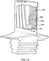
- FIG. 8 shows a gas turbine engine blade 220.
- the blade 220 has an airfoil 222 extending from an inboard end 224 at the outboard surface of a platform 226 to an outboard end or tip 228.
- the airfoil has a leading edge 230 and a trailing edge 232.
- the airfoil has a suction side/surface 234 and a pressure side/surface 236 extending between the leading edge 230 and the trailing edge 232.
- a convoluted attachment root (a so-called "fir-tree" root) 240 depends from an underside (or inboard surface) of the platform 226 and has an inboard (inner diameter or ID) end/surface 242.
- the exemplary blade 220 is cast from an alloy (e.g., a nickel-based superalloy) and has an internal cooling passageway system.
- the exemplary cooling passageway system has a plurality of inlets.
- the exemplary inlets are along the root 240, more particularly along the inboard end/surface 242.
- the exemplary blade has inlets 250A, 250B1-250B4, 250C1-250C3, 252A-252C, and 254A-254C ( FIG. 9 ), discussed further below.
- the exemplary cooling passageway system has a plurality of outlets.
- the exemplary outlets are along the airfoil 222.
- the exemplary outlets include outlets 255A-256C ( FIG. 8 ) along the tip and outlets along the airfoil perimeter.
- Exemplary outlets along the airfoil perimeter include: outlets 256A-256C along the pressure side 236 near the tip 228; outlets 257A and 257B along the pressure side 236 near the platform 226 (e.g., in a trailing inboard quadrant of the pressure side 236); leading edge outlets 258, and trailing edge outlets 260A-260C ( FIG. 8 ).
- Exemplary leading edge outlets are drilled holes.
- the exemplary trailing edge outlets 260A-260C are formed by a trailing edge discharge slot having segments 262A-262C ( FIG. 10 ).
- the exemplary inlets 250A-250C, 252A-252C, and 254A-254C of FIG. 9 each feed a respective passageway trunk extending radially outward within the root.
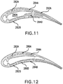
- the exemplary inlet 250A feeds a passageway 280A ( FIG. 11 ) which includes a main portion and a leading edge impingement cavity portion.
- the exemplary passageway 280A generally spans a median of the airfoil cross-section centrally between the pressure side and suction side.
- the exemplary inlets 252A, 252B, and 252C feed respective trunks which merge in the platform to feed a spanwise passageway 282A extending to the outlet 255A.
- the exemplary inlet 254A feeds passageway 282B which extends to the outlet 256A.
- the inlets 250B1 and 250B4 respectively feed passageways 284A and 284B extending to the outlets 255C and 256C, respectively.
- the inlets 250B2 and 250B3 respectively feed passageways 286A and 286B extending to the outlets 255B and 256B.
- the inlet 254B and 254C feed respective trunks of a common passageway 290 ( FIG. 10 ) which, in turn, bifurcates again to feed the respective outlets 257A and 257B.
- the inlet 250C1 feeds a passageway 292A ( FIG. 11 ) of which the segment 262B is an outlet/terminal/downstream portion.
- the inlet 252C2 feeds a passageway 292B ( FIG. 10 ) of which the segment 262C is the outlet/terminal/downstream portion.
- the inlet 250C3 feeds a passageway 292C of which the segment 262A is the outlet/terminal/downstream portion.
- the segments 262A, 262B, and 262C are separately and differently fed via passageways/offset/staggered from each other between pressure and suction sides and normal to the median over at least portions of the extent of those passageways. Similar bends may be provided in the passageways to transition from that stagger to the more aligned condition along the trailing edge.
- FIGS. 13 and 14 show a pattern 320 for casting the blade 220.
- the relationship of the pattern 320 to the blade 220 is the same as the relationship of the pattern 140 to the vane 20.
- the pattern includes a core assembly 322 and a sacrificial pattern material 324 (e.g., wax) molded thereover.
- the core assembly 322 includes a ceramic core 324 which forms the passageway 280A.
- the core assembly 322 further includes refractory metal cores for casting the remaining passageways.
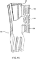
- FIG. 15 shows an alternative core assembly 520 for forming a blade having another segmented trailing edge slot.
- An outboard segment of the slot is cast by an RMC 522 embedded in a trailing leg 524 of a ceramic feedcore.
- An intermediate segment of the slot is cast by a corresponding portion of a pressure side RMC 526.
- An inboard segment is cast by a corresponding portion of a suction side RMC 528.
- the suction side RMC and pressure side RMC trifurcate to each form an exemplary three inlet trunks in the associated blade root adjacent respective trunks of the ceramic core.
- FIG. 16 shows a core assembly 620 for forming yet another blade.
- an outboard segment and an inboard segment of the trailing edge slot are respectively formed by RMCs 622 and 624 having leading portions embedded/mounted in a slot in a trailing ceramic feedcore 626 to secure the RMCs to the feedcore.
- An intermediate segment is cast by a corresponding portion of an RMC 630 extending to the pressure side of the feedcore 626 and having a leading portion embedded in a slot in a leading feedcore 640.
- An upstream portion of the resulting passageway feeding the intermediate segment thus extends to the suction side of the trailing edge feed passageway cast by the core 626 to provide the offset/stagger such as described above.
Landscapes
- Engineering & Computer Science (AREA)
- Mechanical Engineering (AREA)
- General Engineering & Computer Science (AREA)
- Molds, Cores, And Manufacturing Methods Thereof (AREA)
- Turbine Rotor Nozzle Sealing (AREA)
Claims (6)
- Komponente eines Gasturbinenantriebs (20), umfassend:ein Schaufelblatt (22), das Folgendes aufweist:eine Vorderkante (30);eine Hinterkante (32);eine Druckseite (36), die zwischen der Vorderkante (30) und der Hinterkante (32) verläuft;eine Saugseite (34), die zwischen der Vorderkante (30) und der Hinterkante (32) verläuft; undein Kühlkanalsystem, das durch das Schaufelblatt (22) verläuft und Folgendes umfasst:eine Vielzahl von Einlässen (50, 52, 54); undeinen segmentierten Hinterkantenaustrittsschlitz (60),wobei das Kühlkanalsystem eine Vielzahl von Abschnitten umfasst, die zwischen der Druckseite (36) und der Saugseite (34) übereinander angeordnet sind und jeweils unterschiedliche der Segmente (62A-62E) des Hinterkantenaustrittsschlitzes (60) versorgen;dadurch gekennzeichnet, dass:
die übereinander angeordneten Abschnitte, die die Segmente (62A-62E) versorgen, in Fluidverbindung mit verschiedenen der Einlässe (50, 52, 54) stehen. - Komponente nach Anspruch 1, wobei:das Kühlkanalsystem eine Vielzahl von Strängen (70, 72, 74) umfasst, die zwischen der Vorderkante (30) und der Hinterkante (32) übereinander angeordnet sind; undein solcher hinterer Strang eine Vielzahl von übereinander angeordneten Abschnitten (70D, 72D, 74D) aufweist, die jeweils durch zugehörige der übereinander angeordneten Abschnitte gebildet werden.
- Komponente nach Anspruch 1 oder 2, wobei:das Kühlkanalsystem eine Vielzahl von Strängen (70, 72, 74) umfasst, die zwischen der Vorderkante (30) und der Hinterkante (32) übereinander angeordnet sind; undjeder von mindestens zwei Strängen eine Vielzahl von übereinander angeordneten Abschnitten (70D, 72D, 74D, 70C, 72C, 74C) aufweist, die jeweils durch zugehörige der übereinander angeordneten Abschnitte gebildet werden.
- Komponente nach Anspruch 3, wobei: die mindestens zwei Abschnitte jeweils mindestens drei übereinander angeordnete Abschnitte umfassen, von denen zwei (72D, 74D; 72C, 74C) unterschiedliche der Segmente (62A-62E) versorgen und von denen mindestens einer (70D; 70C) dies nicht tut.
- Komponente nach einem der vorstehenden Ansprüche, wobei:
die Komponente (20) eine Leitschaufel ist und die Einlässe (50, 52, 54) sich in einer Außenseite einer Außenverkleidung befinden. - Komponente nach einem der vorstehenden Ansprüche, wobei:
es mindestens drei Segmente (62A-62E) gibt.
Applications Claiming Priority (2)
| Application Number | Priority Date | Filing Date | Title |
|---|---|---|---|
| US12/275,793 US8137068B2 (en) | 2008-11-21 | 2008-11-21 | Castings, casting cores, and methods |
| EP09252633A EP2193859A1 (de) | 2008-11-21 | 2009-11-16 | Gussform, Gusskerne und Verfahren |
Related Parent Applications (2)
| Application Number | Title | Priority Date | Filing Date |
|---|---|---|---|
| EP09252633.4 Division | 2009-11-16 | ||
| EP09252633A Division EP2193859A1 (de) | 2008-11-21 | 2009-11-16 | Gussform, Gusskerne und Verfahren |
Publications (3)
| Publication Number | Publication Date |
|---|---|
| EP2584143A2 EP2584143A2 (de) | 2013-04-24 |
| EP2584143A3 EP2584143A3 (de) | 2017-05-10 |
| EP2584143B1 true EP2584143B1 (de) | 2019-02-20 |
Family
ID=41719358
Family Applications (2)
| Application Number | Title | Priority Date | Filing Date |
|---|---|---|---|
| EP13151206.3A Not-in-force EP2584143B1 (de) | 2008-11-21 | 2009-11-16 | Komponente eines Gasturbinenantriebs |
| EP09252633A Withdrawn EP2193859A1 (de) | 2008-11-21 | 2009-11-16 | Gussform, Gusskerne und Verfahren |
Family Applications After (1)
| Application Number | Title | Priority Date | Filing Date |
|---|---|---|---|
| EP09252633A Withdrawn EP2193859A1 (de) | 2008-11-21 | 2009-11-16 | Gussform, Gusskerne und Verfahren |
Country Status (2)
| Country | Link |
|---|---|
| US (1) | US8137068B2 (de) |
| EP (2) | EP2584143B1 (de) |
Families Citing this family (40)
| Publication number | Priority date | Publication date | Assignee | Title |
|---|---|---|---|---|
| US8171978B2 (en) | 2008-11-21 | 2012-05-08 | United Technologies Corporation | Castings, casting cores, and methods |
| US9403208B2 (en) | 2010-12-30 | 2016-08-02 | United Technologies Corporation | Method and casting core for forming a landing for welding a baffle inserted in an airfoil |
| EP2489836A1 (de) * | 2011-02-21 | 2012-08-22 | Karlsruher Institut für Technologie | Kühlbares Bauteil |
| US8714927B1 (en) * | 2011-07-12 | 2014-05-06 | United Technologies Corporation | Microcircuit skin core cut back to reduce microcircuit trailing edge stresses |
| US9422817B2 (en) * | 2012-05-31 | 2016-08-23 | United Technologies Corporation | Turbine blade root with microcircuit cooling passages |
| US10100646B2 (en) | 2012-08-03 | 2018-10-16 | United Technologies Corporation | Gas turbine engine component cooling circuit |
| US9486854B2 (en) | 2012-09-10 | 2016-11-08 | United Technologies Corporation | Ceramic and refractory metal core assembly |
| US9486853B2 (en) * | 2012-09-14 | 2016-11-08 | United Technologies Corporation | Casting of thin wall hollow airfoil sections |
| US9314838B2 (en) * | 2012-09-28 | 2016-04-19 | Solar Turbines Incorporated | Method of manufacturing a cooled turbine blade with dense cooling fin array |
| SG11201505736UA (en) | 2013-02-14 | 2015-08-28 | United Technologies Corp | Gas turbine engine component having surface indicator |
| EP2821592A1 (de) * | 2013-07-02 | 2015-01-07 | Siemens Aktiengesellschaft | Strömungsleitelement, Kühlmittelüberbrückungsleitung, sowie zugehörige Verfahren zur Montage dieser Kühlmittelüberbrückungsleitung und Gussvorrichtung für die Herstellung eines Strömungsleitelements |
| US10427213B2 (en) | 2013-07-31 | 2019-10-01 | General Electric Company | Turbine blade with sectioned pins and method of making same |
| US9695696B2 (en) | 2013-07-31 | 2017-07-04 | General Electric Company | Turbine blade with sectioned pins |
| EP3060760B1 (de) * | 2013-10-24 | 2018-12-05 | United Technologies Corporation | Schaufel mit aussenkernkühlung |
| US10125614B2 (en) * | 2014-04-17 | 2018-11-13 | United Technologies Corporation | Cooling hole arrangement for engine component |
| FR3021697B1 (fr) * | 2014-05-28 | 2021-09-17 | Snecma | Aube de turbine a refroidissement optimise |
| US20160177732A1 (en) * | 2014-07-22 | 2016-06-23 | United Technologies Corporation | Hollow fan blade for a gas turbine engine |
| US9879554B2 (en) * | 2015-01-09 | 2018-01-30 | Solar Turbines Incorporated | Crimped insert for improved turbine vane internal cooling |
| US10323524B2 (en) | 2015-05-08 | 2019-06-18 | United Technologies Corporation | Axial skin core cooling passage for a turbine engine component |
| US10502066B2 (en) * | 2015-05-08 | 2019-12-10 | United Technologies Corporation | Turbine engine component including an axially aligned skin core passage interrupted by a pedestal |
| US20170002662A1 (en) * | 2015-07-01 | 2017-01-05 | United Technologies Corporation | Gas turbine engine airfoil with bi-axial skin core |
| FR3041989B1 (fr) * | 2015-10-06 | 2020-04-17 | Safran Aircraft Engines | Aube comportant un bord de fuite comprenant trois regions de refroidissement distinctes |
| US9987677B2 (en) | 2015-12-17 | 2018-06-05 | General Electric Company | Method and assembly for forming components having internal passages using a jacketed core |
| US9968991B2 (en) | 2015-12-17 | 2018-05-15 | General Electric Company | Method and assembly for forming components having internal passages using a lattice structure |
| US9579714B1 (en) | 2015-12-17 | 2017-02-28 | General Electric Company | Method and assembly for forming components having internal passages using a lattice structure |
| US10150158B2 (en) | 2015-12-17 | 2018-12-11 | General Electric Company | Method and assembly for forming components having internal passages using a jacketed core |
| US10118217B2 (en) | 2015-12-17 | 2018-11-06 | General Electric Company | Method and assembly for forming components having internal passages using a jacketed core |
| US10099283B2 (en) | 2015-12-17 | 2018-10-16 | General Electric Company | Method and assembly for forming components having an internal passage defined therein |
| US10099276B2 (en) | 2015-12-17 | 2018-10-16 | General Electric Company | Method and assembly for forming components having an internal passage defined therein |
| US10137499B2 (en) | 2015-12-17 | 2018-11-27 | General Electric Company | Method and assembly for forming components having an internal passage defined therein |
| US10046389B2 (en) | 2015-12-17 | 2018-08-14 | General Electric Company | Method and assembly for forming components having internal passages using a jacketed core |
| US10099284B2 (en) | 2015-12-17 | 2018-10-16 | General Electric Company | Method and assembly for forming components having a catalyzed internal passage defined therein |
| US10286450B2 (en) | 2016-04-27 | 2019-05-14 | General Electric Company | Method and assembly for forming components using a jacketed core |
| US10335853B2 (en) | 2016-04-27 | 2019-07-02 | General Electric Company | Method and assembly for forming components using a jacketed core |
| US10605090B2 (en) * | 2016-05-12 | 2020-03-31 | General Electric Company | Intermediate central passage spanning outer walls aft of airfoil leading edge passage |
| US10494930B2 (en) * | 2016-06-16 | 2019-12-03 | General Electric Company | Ceramic matrix composite component cooling |
| FR3079869B1 (fr) * | 2018-04-05 | 2022-05-13 | Safran Aircraft Engines | Aube de turbine haute pression comportant une cavite morte presentant une reduction de section |
| US10753210B2 (en) * | 2018-05-02 | 2020-08-25 | Raytheon Technologies Corporation | Airfoil having improved cooling scheme |
| US10975710B2 (en) * | 2018-12-05 | 2021-04-13 | Raytheon Technologies Corporation | Cooling circuit for gas turbine engine component |
| FR3099523B1 (fr) * | 2019-08-01 | 2021-10-29 | Safran Aircraft Engines | Aube munie d’un circuit de refroidissement |
Family Cites Families (15)
| Publication number | Priority date | Publication date | Assignee | Title |
|---|---|---|---|---|
| US5720431A (en) * | 1988-08-24 | 1998-02-24 | United Technologies Corporation | Cooled blades for a gas turbine engine |
| US5700131A (en) * | 1988-08-24 | 1997-12-23 | United Technologies Corporation | Cooled blades for a gas turbine engine |
| US5931638A (en) * | 1997-08-07 | 1999-08-03 | United Technologies Corporation | Turbomachinery airfoil with optimized heat transfer |
| US6637500B2 (en) * | 2001-10-24 | 2003-10-28 | United Technologies Corporation | Cores for use in precision investment casting |
| US6974308B2 (en) * | 2001-11-14 | 2005-12-13 | Honeywell International, Inc. | High effectiveness cooled turbine vane or blade |
| US7014424B2 (en) * | 2003-04-08 | 2006-03-21 | United Technologies Corporation | Turbine element |
| US6929054B2 (en) * | 2003-12-19 | 2005-08-16 | United Technologies Corporation | Investment casting cores |
| US7134475B2 (en) * | 2004-10-29 | 2006-11-14 | United Technologies Corporation | Investment casting cores and methods |
| US7255535B2 (en) * | 2004-12-02 | 2007-08-14 | Albrecht Harry A | Cooling systems for stacked laminate CMC vane |
| US7377746B2 (en) * | 2005-02-21 | 2008-05-27 | General Electric Company | Airfoil cooling circuits and method |
| US7438527B2 (en) * | 2005-04-22 | 2008-10-21 | United Technologies Corporation | Airfoil trailing edge cooling |
| US7270515B2 (en) * | 2005-05-26 | 2007-09-18 | Siemens Power Generation, Inc. | Turbine airfoil trailing edge cooling system with segmented impingement ribs |
| US7303375B2 (en) * | 2005-11-23 | 2007-12-04 | United Technologies Corporation | Refractory metal core cooling technologies for curved leading edge slots |
| US7731481B2 (en) | 2006-12-18 | 2010-06-08 | United Technologies Corporation | Airfoil cooling with staggered refractory metal core microcircuits |
| US9163518B2 (en) * | 2008-03-18 | 2015-10-20 | United Technologies Corporation | Full coverage trailing edge microcircuit with alternating converging exits |
-
2008
- 2008-11-21 US US12/275,793 patent/US8137068B2/en not_active Expired - Fee Related
-
2009
- 2009-11-16 EP EP13151206.3A patent/EP2584143B1/de not_active Not-in-force
- 2009-11-16 EP EP09252633A patent/EP2193859A1/de not_active Withdrawn
Non-Patent Citations (1)
| Title |
|---|
| None * |
Also Published As
| Publication number | Publication date |
|---|---|
| US8137068B2 (en) | 2012-03-20 |
| EP2193859A1 (de) | 2010-06-09 |
| US20100129195A1 (en) | 2010-05-27 |
| EP2584143A2 (de) | 2013-04-24 |
| EP2584143A3 (de) | 2017-05-10 |
Similar Documents
| Publication | Publication Date | Title |
|---|---|---|
| EP2584143B1 (de) | Komponente eines Gasturbinenantriebs | |
| US8171978B2 (en) | Castings, casting cores, and methods | |
| EP2191910B1 (de) | Gussteilen, Gusskerne und Verfahren | |
| US8100165B2 (en) | Investment casting cores and methods | |
| EP2298469B1 (de) | Feingusskerne und deren Anwendung beim Feingiessen | |
| EP1854567B1 (de) | Profilierter metallener Gusskern | |
| EP1992431B1 (de) | Präzisionsgusskerne und Verfahren | |
| US8251123B2 (en) | Casting core assembly methods | |
| EP2335845B1 (de) | Verfahren zur Herstellung eines Gussteils | |
| US10821501B2 (en) | Coated casting core and manufacture methods | |
| EP2399693B1 (de) | Profilierter metallener Gusskern |
Legal Events
| Date | Code | Title | Description |
|---|---|---|---|
| PUAI | Public reference made under article 153(3) epc to a published international application that has entered the european phase |
Free format text: ORIGINAL CODE: 0009012 |
|
| AC | Divisional application: reference to earlier application |
Ref document number: 2193859 Country of ref document: EP Kind code of ref document: P |
|
| AK | Designated contracting states |
Kind code of ref document: A2 Designated state(s): AT BE BG CH CY CZ DE DK EE ES FI FR GB GR HR HU IE IS IT LI LT LU LV MC MK MT NL NO PL PT RO SE SI SK SM TR |
|
| RIN1 | Information on inventor provided before grant (corrected) |
Inventor name: SURACE, RAYMOND Inventor name: RAMLOGAN, AMARNATH Inventor name: CHEROLIS, ANTHONY P. Inventor name: LETIZIA, ERIC P. Inventor name: PROPHETER-HINCKLEY, TRACY A. Inventor name: PIGGUISH, JUSTIN D. Inventor name: DEVORE, MATTHEW A. Inventor name: XUE, YONGXIANG D. |
|
| RAP1 | Party data changed (applicant data changed or rights of an application transferred) |
Owner name: UNITED TECHNOLOGIES CORPORATION |
|
| REG | Reference to a national code |
Ref country code: DE Ref legal event code: R079 Ref document number: 602009057139 Country of ref document: DE Free format text: PREVIOUS MAIN CLASS: F01D0005080000 Ipc: B22C0007020000 |
|
| PUAL | Search report despatched |
Free format text: ORIGINAL CODE: 0009013 |
|
| AK | Designated contracting states |
Kind code of ref document: A3 Designated state(s): AT BE BG CH CY CZ DE DK EE ES FI FR GB GR HR HU IE IS IT LI LT LU LV MC MK MT NL NO PL PT RO SE SI SK SM TR |
|
| RIC1 | Information provided on ipc code assigned before grant |
Ipc: B22C 7/02 20060101AFI20170406BHEP Ipc: B22C 9/04 20060101ALI20170406BHEP Ipc: F01D 5/18 20060101ALI20170406BHEP Ipc: F01D 5/14 20060101ALI20170406BHEP Ipc: B22C 9/10 20060101ALI20170406BHEP |
|
| STAA | Information on the status of an ep patent application or granted ep patent |
Free format text: STATUS: REQUEST FOR EXAMINATION WAS MADE |
|
| 17P | Request for examination filed |
Effective date: 20171108 |
|
| RBV | Designated contracting states (corrected) |
Designated state(s): AT BE BG CH CY CZ DE DK EE ES FI FR GB GR HR HU IE IS IT LI LT LU LV MC MK MT NL NO PL PT RO SE SI SK SM TR |
|
| GRAP | Despatch of communication of intention to grant a patent |
Free format text: ORIGINAL CODE: EPIDOSNIGR1 |
|
| STAA | Information on the status of an ep patent application or granted ep patent |
Free format text: STATUS: GRANT OF PATENT IS INTENDED |
|
| INTG | Intention to grant announced |
Effective date: 20180817 |
|
| GRAS | Grant fee paid |
Free format text: ORIGINAL CODE: EPIDOSNIGR3 |
|
| GRAA | (expected) grant |
Free format text: ORIGINAL CODE: 0009210 |
|
| STAA | Information on the status of an ep patent application or granted ep patent |
Free format text: STATUS: THE PATENT HAS BEEN GRANTED |
|
| AC | Divisional application: reference to earlier application |
Ref document number: 2193859 Country of ref document: EP Kind code of ref document: P |
|
| AK | Designated contracting states |
Kind code of ref document: B1 Designated state(s): AT BE BG CH CY CZ DE DK EE ES FI FR GB GR HR HU IE IS IT LI LT LU LV MC MK MT NL NO PL PT RO SE SI SK SM TR |
|
| REG | Reference to a national code |
Ref country code: GB Ref legal event code: FG4D |
|
| REG | Reference to a national code |
Ref country code: CH Ref legal event code: EP |
|
| REG | Reference to a national code |
Ref country code: AT Ref legal event code: REF Ref document number: 1097518 Country of ref document: AT Kind code of ref document: T Effective date: 20190315 |
|
| REG | Reference to a national code |
Ref country code: IE Ref legal event code: FG4D |
|
| REG | Reference to a national code |
Ref country code: DE Ref legal event code: R096 Ref document number: 602009057139 Country of ref document: DE |
|
| REG | Reference to a national code |
Ref country code: NL Ref legal event code: MP Effective date: 20190220 |
|
| REG | Reference to a national code |
Ref country code: LT Ref legal event code: MG4D |
|
| PG25 | Lapsed in a contracting state [announced via postgrant information from national office to epo] |
Ref country code: NL Free format text: LAPSE BECAUSE OF FAILURE TO SUBMIT A TRANSLATION OF THE DESCRIPTION OR TO PAY THE FEE WITHIN THE PRESCRIBED TIME-LIMIT Effective date: 20190220 Ref country code: LT Free format text: LAPSE BECAUSE OF FAILURE TO SUBMIT A TRANSLATION OF THE DESCRIPTION OR TO PAY THE FEE WITHIN THE PRESCRIBED TIME-LIMIT Effective date: 20190220 Ref country code: FI Free format text: LAPSE BECAUSE OF FAILURE TO SUBMIT A TRANSLATION OF THE DESCRIPTION OR TO PAY THE FEE WITHIN THE PRESCRIBED TIME-LIMIT Effective date: 20190220 Ref country code: PT Free format text: LAPSE BECAUSE OF FAILURE TO SUBMIT A TRANSLATION OF THE DESCRIPTION OR TO PAY THE FEE WITHIN THE PRESCRIBED TIME-LIMIT Effective date: 20190620 Ref country code: NO Free format text: LAPSE BECAUSE OF FAILURE TO SUBMIT A TRANSLATION OF THE DESCRIPTION OR TO PAY THE FEE WITHIN THE PRESCRIBED TIME-LIMIT Effective date: 20190520 Ref country code: SE Free format text: LAPSE BECAUSE OF FAILURE TO SUBMIT A TRANSLATION OF THE DESCRIPTION OR TO PAY THE FEE WITHIN THE PRESCRIBED TIME-LIMIT Effective date: 20190220 |
|
| PG25 | Lapsed in a contracting state [announced via postgrant information from national office to epo] |
Ref country code: HR Free format text: LAPSE BECAUSE OF FAILURE TO SUBMIT A TRANSLATION OF THE DESCRIPTION OR TO PAY THE FEE WITHIN THE PRESCRIBED TIME-LIMIT Effective date: 20190220 Ref country code: GR Free format text: LAPSE BECAUSE OF FAILURE TO SUBMIT A TRANSLATION OF THE DESCRIPTION OR TO PAY THE FEE WITHIN THE PRESCRIBED TIME-LIMIT Effective date: 20190521 Ref country code: LV Free format text: LAPSE BECAUSE OF FAILURE TO SUBMIT A TRANSLATION OF THE DESCRIPTION OR TO PAY THE FEE WITHIN THE PRESCRIBED TIME-LIMIT Effective date: 20190220 Ref country code: IS Free format text: LAPSE BECAUSE OF FAILURE TO SUBMIT A TRANSLATION OF THE DESCRIPTION OR TO PAY THE FEE WITHIN THE PRESCRIBED TIME-LIMIT Effective date: 20190620 Ref country code: BG Free format text: LAPSE BECAUSE OF FAILURE TO SUBMIT A TRANSLATION OF THE DESCRIPTION OR TO PAY THE FEE WITHIN THE PRESCRIBED TIME-LIMIT Effective date: 20190520 |
|
| REG | Reference to a national code |
Ref country code: AT Ref legal event code: MK05 Ref document number: 1097518 Country of ref document: AT Kind code of ref document: T Effective date: 20190220 |
|
| PG25 | Lapsed in a contracting state [announced via postgrant information from national office to epo] |
Ref country code: EE Free format text: LAPSE BECAUSE OF FAILURE TO SUBMIT A TRANSLATION OF THE DESCRIPTION OR TO PAY THE FEE WITHIN THE PRESCRIBED TIME-LIMIT Effective date: 20190220 Ref country code: SK Free format text: LAPSE BECAUSE OF FAILURE TO SUBMIT A TRANSLATION OF THE DESCRIPTION OR TO PAY THE FEE WITHIN THE PRESCRIBED TIME-LIMIT Effective date: 20190220 Ref country code: RO Free format text: LAPSE BECAUSE OF FAILURE TO SUBMIT A TRANSLATION OF THE DESCRIPTION OR TO PAY THE FEE WITHIN THE PRESCRIBED TIME-LIMIT Effective date: 20190220 Ref country code: ES Free format text: LAPSE BECAUSE OF FAILURE TO SUBMIT A TRANSLATION OF THE DESCRIPTION OR TO PAY THE FEE WITHIN THE PRESCRIBED TIME-LIMIT Effective date: 20190220 Ref country code: CZ Free format text: LAPSE BECAUSE OF FAILURE TO SUBMIT A TRANSLATION OF THE DESCRIPTION OR TO PAY THE FEE WITHIN THE PRESCRIBED TIME-LIMIT Effective date: 20190220 Ref country code: IT Free format text: LAPSE BECAUSE OF FAILURE TO SUBMIT A TRANSLATION OF THE DESCRIPTION OR TO PAY THE FEE WITHIN THE PRESCRIBED TIME-LIMIT Effective date: 20190220 Ref country code: DK Free format text: LAPSE BECAUSE OF FAILURE TO SUBMIT A TRANSLATION OF THE DESCRIPTION OR TO PAY THE FEE WITHIN THE PRESCRIBED TIME-LIMIT Effective date: 20190220 |
|
| REG | Reference to a national code |
Ref country code: DE Ref legal event code: R097 Ref document number: 602009057139 Country of ref document: DE |
|
| PG25 | Lapsed in a contracting state [announced via postgrant information from national office to epo] |
Ref country code: PL Free format text: LAPSE BECAUSE OF FAILURE TO SUBMIT A TRANSLATION OF THE DESCRIPTION OR TO PAY THE FEE WITHIN THE PRESCRIBED TIME-LIMIT Effective date: 20190220 Ref country code: SM Free format text: LAPSE BECAUSE OF FAILURE TO SUBMIT A TRANSLATION OF THE DESCRIPTION OR TO PAY THE FEE WITHIN THE PRESCRIBED TIME-LIMIT Effective date: 20190220 |
|
| PLBE | No opposition filed within time limit |
Free format text: ORIGINAL CODE: 0009261 |
|
| STAA | Information on the status of an ep patent application or granted ep patent |
Free format text: STATUS: NO OPPOSITION FILED WITHIN TIME LIMIT |
|
| PG25 | Lapsed in a contracting state [announced via postgrant information from national office to epo] |
Ref country code: AT Free format text: LAPSE BECAUSE OF FAILURE TO SUBMIT A TRANSLATION OF THE DESCRIPTION OR TO PAY THE FEE WITHIN THE PRESCRIBED TIME-LIMIT Effective date: 20190220 |
|
| 26N | No opposition filed |
Effective date: 20191121 |
|
| PGFP | Annual fee paid to national office [announced via postgrant information from national office to epo] |
Ref country code: DE Payment date: 20191021 Year of fee payment: 11 |
|
| PG25 | Lapsed in a contracting state [announced via postgrant information from national office to epo] |
Ref country code: SI Free format text: LAPSE BECAUSE OF FAILURE TO SUBMIT A TRANSLATION OF THE DESCRIPTION OR TO PAY THE FEE WITHIN THE PRESCRIBED TIME-LIMIT Effective date: 20190220 |
|
| PGFP | Annual fee paid to national office [announced via postgrant information from national office to epo] |
Ref country code: FR Payment date: 20191022 Year of fee payment: 11 |
|
| PG25 | Lapsed in a contracting state [announced via postgrant information from national office to epo] |
Ref country code: TR Free format text: LAPSE BECAUSE OF FAILURE TO SUBMIT A TRANSLATION OF THE DESCRIPTION OR TO PAY THE FEE WITHIN THE PRESCRIBED TIME-LIMIT Effective date: 20190220 |
|
| PGFP | Annual fee paid to national office [announced via postgrant information from national office to epo] |
Ref country code: GB Payment date: 20191022 Year of fee payment: 11 |
|
| REG | Reference to a national code |
Ref country code: CH Ref legal event code: PL |
|
| PG25 | Lapsed in a contracting state [announced via postgrant information from national office to epo] |
Ref country code: LI Free format text: LAPSE BECAUSE OF NON-PAYMENT OF DUE FEES Effective date: 20191130 Ref country code: CH Free format text: LAPSE BECAUSE OF NON-PAYMENT OF DUE FEES Effective date: 20191130 Ref country code: MC Free format text: LAPSE BECAUSE OF FAILURE TO SUBMIT A TRANSLATION OF THE DESCRIPTION OR TO PAY THE FEE WITHIN THE PRESCRIBED TIME-LIMIT Effective date: 20190220 Ref country code: LU Free format text: LAPSE BECAUSE OF NON-PAYMENT OF DUE FEES Effective date: 20191116 |
|
| REG | Reference to a national code |
Ref country code: BE Ref legal event code: MM Effective date: 20191130 |
|
| PG25 | Lapsed in a contracting state [announced via postgrant information from national office to epo] |
Ref country code: IE Free format text: LAPSE BECAUSE OF NON-PAYMENT OF DUE FEES Effective date: 20191116 |
|
| PG25 | Lapsed in a contracting state [announced via postgrant information from national office to epo] |
Ref country code: BE Free format text: LAPSE BECAUSE OF NON-PAYMENT OF DUE FEES Effective date: 20191130 |
|
| PG25 | Lapsed in a contracting state [announced via postgrant information from national office to epo] |
Ref country code: CY Free format text: LAPSE BECAUSE OF FAILURE TO SUBMIT A TRANSLATION OF THE DESCRIPTION OR TO PAY THE FEE WITHIN THE PRESCRIBED TIME-LIMIT Effective date: 20190220 |
|
| REG | Reference to a national code |
Ref country code: DE Ref legal event code: R119 Ref document number: 602009057139 Country of ref document: DE |
|
| GBPC | Gb: european patent ceased through non-payment of renewal fee |
Effective date: 20201116 |
|
| PG25 | Lapsed in a contracting state [announced via postgrant information from national office to epo] |
Ref country code: MT Free format text: LAPSE BECAUSE OF FAILURE TO SUBMIT A TRANSLATION OF THE DESCRIPTION OR TO PAY THE FEE WITHIN THE PRESCRIBED TIME-LIMIT Effective date: 20190220 Ref country code: HU Free format text: LAPSE BECAUSE OF FAILURE TO SUBMIT A TRANSLATION OF THE DESCRIPTION OR TO PAY THE FEE WITHIN THE PRESCRIBED TIME-LIMIT; INVALID AB INITIO Effective date: 20091116 |
|
| PG25 | Lapsed in a contracting state [announced via postgrant information from national office to epo] |
Ref country code: FR Free format text: LAPSE BECAUSE OF NON-PAYMENT OF DUE FEES Effective date: 20201130 |
|
| PG25 | Lapsed in a contracting state [announced via postgrant information from national office to epo] |
Ref country code: GB Free format text: LAPSE BECAUSE OF NON-PAYMENT OF DUE FEES Effective date: 20201116 Ref country code: DE Free format text: LAPSE BECAUSE OF NON-PAYMENT OF DUE FEES Effective date: 20210601 |
|
| PG25 | Lapsed in a contracting state [announced via postgrant information from national office to epo] |
Ref country code: MK Free format text: LAPSE BECAUSE OF FAILURE TO SUBMIT A TRANSLATION OF THE DESCRIPTION OR TO PAY THE FEE WITHIN THE PRESCRIBED TIME-LIMIT Effective date: 20190220 |