EP2584145A1 - Gekühlte Turbinenleitschaufel oder gekühltes Turbinenleitblatt für eine Turbomaschine - Google Patents
Gekühlte Turbinenleitschaufel oder gekühltes Turbinenleitblatt für eine Turbomaschine Download PDFInfo
- Publication number
- EP2584145A1 EP2584145A1 EP11185955.9A EP11185955A EP2584145A1 EP 2584145 A1 EP2584145 A1 EP 2584145A1 EP 11185955 A EP11185955 A EP 11185955A EP 2584145 A1 EP2584145 A1 EP 2584145A1
- Authority
- EP
- European Patent Office
- Prior art keywords
- side wall
- airfoil
- turbine
- suction side
- turbine airfoil
- Prior art date
- Legal status (The legal status is an assumption and is not a legal conclusion. Google has not performed a legal analysis and makes no representation as to the accuracy of the status listed.)
- Withdrawn
Links
- 238000001816 cooling Methods 0.000 claims abstract description 38
- 239000012809 cooling fluid Substances 0.000 claims abstract description 36
- NJPPVKZQTLUDBO-UHFFFAOYSA-N novaluron Chemical compound C1=C(Cl)C(OC(F)(F)C(OC(F)(F)F)F)=CC=C1NC(=O)NC(=O)C1=C(F)C=CC=C1F NJPPVKZQTLUDBO-UHFFFAOYSA-N 0.000 description 7
- 238000000926 separation method Methods 0.000 description 3
- 230000015572 biosynthetic process Effects 0.000 description 2
- 230000000694 effects Effects 0.000 description 2
- 239000000463 material Substances 0.000 description 2
- 230000004888 barrier function Effects 0.000 description 1
- 238000005524 ceramic coating Methods 0.000 description 1
- 238000002485 combustion reaction Methods 0.000 description 1
- 238000007599 discharging Methods 0.000 description 1
- 239000011796 hollow space material Substances 0.000 description 1
- 239000012720 thermal barrier coating Substances 0.000 description 1
Images
Classifications
-
- F—MECHANICAL ENGINEERING; LIGHTING; HEATING; WEAPONS; BLASTING
- F01—MACHINES OR ENGINES IN GENERAL; ENGINE PLANTS IN GENERAL; STEAM ENGINES
- F01D—NON-POSITIVE DISPLACEMENT MACHINES OR ENGINES, e.g. STEAM TURBINES
- F01D5/00—Blades; Blade-carrying members; Heating, heat-insulating, cooling or antivibration means on the blades or the members
- F01D5/12—Blades
- F01D5/14—Form or construction
- F01D5/18—Hollow blades, i.e. blades with cooling or heating channels or cavities; Heating, heat-insulating or cooling means on blades
- F01D5/187—Convection cooling
-
- F—MECHANICAL ENGINEERING; LIGHTING; HEATING; WEAPONS; BLASTING
- F01—MACHINES OR ENGINES IN GENERAL; ENGINE PLANTS IN GENERAL; STEAM ENGINES
- F01D—NON-POSITIVE DISPLACEMENT MACHINES OR ENGINES, e.g. STEAM TURBINES
- F01D5/00—Blades; Blade-carrying members; Heating, heat-insulating, cooling or antivibration means on the blades or the members
- F01D5/12—Blades
- F01D5/14—Form or construction
- F01D5/18—Hollow blades, i.e. blades with cooling or heating channels or cavities; Heating, heat-insulating or cooling means on blades
- F01D5/186—Film cooling
-
- F—MECHANICAL ENGINEERING; LIGHTING; HEATING; WEAPONS; BLASTING
- F01—MACHINES OR ENGINES IN GENERAL; ENGINE PLANTS IN GENERAL; STEAM ENGINES
- F01D—NON-POSITIVE DISPLACEMENT MACHINES OR ENGINES, e.g. STEAM TURBINES
- F01D9/00—Stators
- F01D9/06—Fluid supply conduits to nozzles or the like
- F01D9/065—Fluid supply or removal conduits traversing the working fluid flow, e.g. for lubrication-, cooling-, or sealing fluids
-
- F—MECHANICAL ENGINEERING; LIGHTING; HEATING; WEAPONS; BLASTING
- F05—INDEXING SCHEMES RELATING TO ENGINES OR PUMPS IN VARIOUS SUBCLASSES OF CLASSES F01-F04
- F05D—INDEXING SCHEME FOR ASPECTS RELATING TO NON-POSITIVE-DISPLACEMENT MACHINES OR ENGINES, GAS-TURBINES OR JET-PROPULSION PLANTS
- F05D2260/00—Function
- F05D2260/20—Heat transfer, e.g. cooling
- F05D2260/203—Heat transfer, e.g. cooling by transpiration cooling
Definitions
- the invention relates to a cooled blading of a turbine.
- a turbomachine in particular a gas turbine, comprises a turbine in which a hot gas is expanded for attaining a mechanical work, after the hot gas had been compressed in a compressor and heated up in a combustion chamber.
- the latter is designed as an axial gas turbine, wherein the turbine comprises a plurality of consecutive blade rings.
- the blade rings comprise alternately guide vanes attached to the housing of the gas turbine and rotor blades attached to a rotor of the gas turbine.
- Guide vanes and/or rotor blades can be referred to as blading.
- a single vane or guide vane or a single blade or rotor blade is also called airfoil as a more general term.
- the maximal acceptable inlet temperature is limited because of the limited thermal resilience of the turbine blading. It is desirable to design a turbine blading which can cope with a high thermal load but it must have a sufficient mechanical stability.
- Conventional turbine bladings comprise materials or combinations of materials which allow only part of the potential for raising the thermal efficiency of the gas turbine. For a further rise of the inlet temperature it is known to cool the turbine blading, so that it is subjected to a lower thermal load due to the hot gas than it would be without the cooling.
- the inventive turbine airfoil particularly a blade or a vane for a turbomachine, comprises a suction side wall and a pressure side wall bordering a airfoil cavity, which is adapted to be flowed through by a cooling fluid for cooling of the side walls and therefore of the turbine airfoil, wherein the suction side wall comprises at least one protrusion extending therefrom inside the cavity, wherein the number, the distribution, the location and/or the shape of the at least one protrusion are such that the heat transfer from the suction side wall to the cooling fluid is higher compared to the heat transfer from the pressure side wall to the cooling fluid during the operation of the turbomachine such that an excess of the heat transfer from the suction side wall is generated.
- the airfoil may particularly be a film cooled airfoil.
- film cooling is provided via film cooling holes in the side walls of the airfoil.
- the inventive turbine airfoil or turbine blading can be a rotating blade or a stationary guide vane.
- the inventive turbine blading comprises one protrusion or a plurality of protrusions.
- the walls of the turbine blade or guide vane are heated up due to hot gas flowing along the external walls. Heat is transported by heat conduction to the protrusion of the suction side wall.
- the protrusion has the effect of increasing the inner surface of the suction side wall, whereby convective cooling by the cooling fluid flowing through the cavity is increased.
- the cooling may particularly be film cooling and/or convective cooling.
- the overall cooling of the suction side wall comprises a contribution from the convective cooling from inside the turbine airfoil and may have an additional contribution from the film cooling from outside the blade or guide vane. Because of the increased heat transfer of the convective cooling, a reduced amount of the cooling fluid overall for the blading or specifically for the external film cooling can be used for the suction side wall.
- the velocity of hot gas during the operation of the turbomachine is higher compared to that of the pressure side wall. Therefore, mixing losses in areas with high velocity gradients between the hot gas and the cooling fluid are reduced and consequently the efficiency of the turbomachine is advantageously increased.
- the extension of the protrusion should be specified such that a compromise is found between the large inner surface for an effective cooling and a small blockage for the cooling fluid flow inside the cavity.
- At least one of the protrusions is a turbulator for the cooling fluid flow. Downstream from the turbulator a turbulent boundary layer is developing, which advantageously cools the suction side wall efficiently by the convective cooling.
- At least one of the protrusions is preferably a cylinder, a cone, a pyramid or a tetrahedron.
- at least one of the protrusions is preferably an elongated rib, in particular with a triangular cross section. The elongated rib can advantageously increase the mechanical stability of the turbine blading. It is preferred that on the downstream side of the protrusion a flow separation, which would lead to a formation of a recirculation zone, is prevented. The cooling fluid can be trapped in the recirculation zone, whereby the convective cooling would be affected. With the preferred shapes of the protrusion a large surface inside the turbine airfoil with a small blockage for the cooling fluid flow can advantageously be achieved.
- At least one of the protrusions extends from the suction side wall to the pressure side wall.
- the turbine airfoil has consequently a high mechanical stability.
- the thickness of the protrusion portion attached to the suction side wall is preferably larger than the thickness of the protrusion portion attached to the pressure side wall.
- At least one of the protrusions is preferably a truncated cone and/or a cylinder. Further, it is preferred that at least one of the protrusions is located adjacent to the trailing edge of the turbine blade or guide vane.
- Cooling is in particular important near the trailing edge and the protrusion adjacent to the trailing edge increases advantageously the convective cooling in this area.
- the turbine blade or vane comprises at least one passage in the trailing edge connecting the cavity with the outside of the blade or vane, wherein the passage is provided for the outflow of the cooling fluid from the cavity. Therefore, the flow of the cooling fluid around the protrusion adjacent to the trailing edge is high and the convective cooling of this protrusion is advantageously high.
- the suction side wall comprises a plurality of film cooling holes. Via the film cooling holes the cooling fluid is transported from the cavity to the surface of the blade or vane in order to form a cooling film on the turbine blade or vane surface, i.e. the outside surface of the airfoil along which the hot gas will pass during operation.
- the suction side wall can advantageously be cooled both from inside and outside of the blade or vane, i.e. the airfoil or the blading.
- the cooling film not only cools the airfoil by convection but it also functions as a barrier against the hot gas to prevent the hot gas from flowing at the turbine airfoil wall.
- the number and/or the diameter of the film cooling holes are preferably minimised subject to a compensation of the excess of the heat transfer caused by the protrusions. Due to the minimised number and/or diameter of the film cooling holes the amount of cooling fluid transported on the turbine airfoil surface of the suction side wall is minimised as well. Consequently, the mixing losses of the cooling fluid and the hot gas are advantageously lower while the heat transfer from the suction side wall to the cooling fluid is unchanged.
- the turbine blade or vane comprises on its outer surface a thermal barrier coating, e.g. a ceramic coating, to increase the thermal resilience of the turbine blading and therefore increase the lifetime of the turbine blading.
- a thermal barrier coating e.g. a ceramic coating
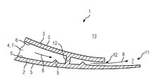
- FIG. 1 an embodiment of a turbine airfoil 1 of a turbomachine is shown.
- the turbine airfoil 1 can be a rotor blade as well as a guide vane.
- the turbine airfoil 1 comprises a suction side wall 2 and a pressure side wall 3 which border a cavity 4 - an airfoil cavity, a hollow space inside the airfoil 1 - inside the turbine airfoil 1.
- the trailing edge 11 of the turbine airfoil 1 and the area adjacent to the trailing edge 11 are shown.
- the width of the cavity 4 reduces towards the trailing edge 11.
- Each of the walls 2, 3 comprises an inner face 6 and an outer face 5.
- a hot gas (not shown) flows in the flow channel 13 between two adjacent turbine airfoils along the walls 2, 3 with a main flow direction directed from the leading edge (not shown) to the trailing edge 11.
- a cooling fluid 7 flows with a cooling fluid main flow direction 8 which is substantially parallel to the walls 2, 3 and oriented towards the trailing edge 11.
- the turbine airfoil 1 comprises a passage 12 via which the cooling fluid 7 discharges the cavity 4.
- the suction side wall 2 is more elongated than the pressure side wall 3, so that after discharging the cavity 4 the cooling fluid 7 flows along the inner face 6 of the suction side wall, providing a flow or film of cooling fluid. It is also possible that the suction side wall 2 and the pressure side wall 3 are the same length.
- the suction side wall 2 comprises two protrusions 9 extending therefrom inside the cavity 4. Possible is also that the suction side wall 2 comprises one protrusion 9 or a plurality of protrusions 9.
- the protrusions 9 have a conical shape with the base of the cone arranged on the inner face 6 of the suction side wall 2. With the protrusions 9 a large surface inside the turbine airfoil 1 with a small blockage for the cooling fluid 7 flow can be achieved.
- the shape of the cone is preferably such that the edge of the cone has such a large angle that a flow separation downstream of the cone, which would result in the formation of a recirculation zone, is avoided.
- Other shapes of the protrusions 9 are also possible, for example a truncated cone, with the larger base arranged on the suction side wall, a shape that would particularly prevent the flow separation.
- the protrusions 9 have such a shape that they function as turbulators.
- the turbulators have the effect that downstream of the cooling fluid 7 main flow direction 8, the cooling fluid 7 flow originating from the turbulators has increased turbulence.
- a cooling fluid 7 flow with enhanced turbulence cools the suction side wall 2 more efficiently by convective cooling than a cooling flow 7 along a smooth surface which may substantially form a film on the surface.
- a pedestal 10 with a cylindrical shape which is arranged between both protrusions 9 and extends from the suction side wall 2 to the pressure side wall 3.
- the pedestal can also have an e.g. rectangular cross section.
- the pedestal 10 in order to have a higher heat transfer from the suction side wall 2 can be a truncated cone, with the larger base of the truncated cone arranged on the suction side wall 2 and the smaller base arranged on the pressure side wall 3.
- the pedestal 10 comprises a truncated cone, which is arranged with its larger base at the suction side wall 2 and at its smaller base a cylinder is arranged, which extends to the pressure side wall 3.
- the diameter of the pedestal 10 is chosen such that sufficient cooling fluid 7 for the convective cooling can be flown around the pedestal. It is preferred that the protrusions 9 and the pedestal 10 are arranged at gap, so that they are not in the flow shadow zone of each other. It is also preferred that the protrusions 9 and the pedestals 10 are arranged in a distance from the tip or hub, leading edge and trailing edge 11 of the airfoil 1, so that sufficient cooling air 7 can be provided for these areas.
- the turbine airfoil 1 comprises a plurality of film cooling holes in the walls 2, 3. Due to the protrusions 9 on the suction side wall 2 the distance between film cooling holes can be increased and the total flow of air reduced, compared to an airfoil 1 with the protrusions 9, whereby the contribution of the film cooling is smaller on the suction side wall 2. Hence, losses due to mixing of the hot gas and the cooling fluid 7 on the suction side wall 2 are reduced. Also possible is that sufficient cooling from inside the airfoil 1 is achieved due to the protrusions so that the film cooling can be completely eliminated.
Landscapes
- Engineering & Computer Science (AREA)
- Mechanical Engineering (AREA)
- General Engineering & Computer Science (AREA)
- Physics & Mathematics (AREA)
- Fluid Mechanics (AREA)
- Turbine Rotor Nozzle Sealing (AREA)
Priority Applications (4)
| Application Number | Priority Date | Filing Date | Title |
|---|---|---|---|
| EP11185955.9A EP2584145A1 (de) | 2011-10-20 | 2011-10-20 | Gekühlte Turbinenleitschaufel oder gekühltes Turbinenleitblatt für eine Turbomaschine |
| US14/352,106 US9896942B2 (en) | 2011-10-20 | 2012-10-02 | Cooled turbine guide vane or blade for a turbomachine |
| EP12769090.7A EP2785979B1 (de) | 2011-10-20 | 2012-10-02 | Gekühlte turbinenleitschaufel oder gekühltes turbinenleitblatt für eine turbomaschine |
| PCT/EP2012/069396 WO2013056975A1 (en) | 2011-10-20 | 2012-10-02 | A cooled turbine guide vane or blade for a turbomachine |
Applications Claiming Priority (1)
| Application Number | Priority Date | Filing Date | Title |
|---|---|---|---|
| EP11185955.9A EP2584145A1 (de) | 2011-10-20 | 2011-10-20 | Gekühlte Turbinenleitschaufel oder gekühltes Turbinenleitblatt für eine Turbomaschine |
Publications (1)
| Publication Number | Publication Date |
|---|---|
| EP2584145A1 true EP2584145A1 (de) | 2013-04-24 |
Family
ID=46980950
Family Applications (2)
| Application Number | Title | Priority Date | Filing Date |
|---|---|---|---|
| EP11185955.9A Withdrawn EP2584145A1 (de) | 2011-10-20 | 2011-10-20 | Gekühlte Turbinenleitschaufel oder gekühltes Turbinenleitblatt für eine Turbomaschine |
| EP12769090.7A Not-in-force EP2785979B1 (de) | 2011-10-20 | 2012-10-02 | Gekühlte turbinenleitschaufel oder gekühltes turbinenleitblatt für eine turbomaschine |
Family Applications After (1)
| Application Number | Title | Priority Date | Filing Date |
|---|---|---|---|
| EP12769090.7A Not-in-force EP2785979B1 (de) | 2011-10-20 | 2012-10-02 | Gekühlte turbinenleitschaufel oder gekühltes turbinenleitblatt für eine turbomaschine |
Country Status (3)
| Country | Link |
|---|---|
| US (1) | US9896942B2 (de) |
| EP (2) | EP2584145A1 (de) |
| WO (1) | WO2013056975A1 (de) |
Cited By (2)
| Publication number | Priority date | Publication date | Assignee | Title |
|---|---|---|---|---|
| WO2015073092A3 (en) * | 2013-09-05 | 2015-08-06 | United Technologies Corporation | Gas turbine engine airfoil turbulator for airfoil creep resistance |
| EP3323978A1 (de) * | 2016-11-16 | 2018-05-23 | General Electric Company | Turbinenanordnung |
Families Citing this family (12)
| Publication number | Priority date | Publication date | Assignee | Title |
|---|---|---|---|---|
| US20150152738A1 (en) * | 2013-12-02 | 2015-06-04 | George Liang | Turbine airfoil cooling passage with diamond turbulator |
| CA2935398A1 (en) | 2015-07-31 | 2017-01-31 | Rolls-Royce Corporation | Turbine airfoils with micro cooling features |
| US10344598B2 (en) * | 2015-12-03 | 2019-07-09 | General Electric Company | Trailing edge cooling for a turbine blade |
| US11149555B2 (en) | 2017-06-14 | 2021-10-19 | General Electric Company | Turbine engine component with deflector |
| US11499433B2 (en) | 2018-12-18 | 2022-11-15 | General Electric Company | Turbine engine component and method of cooling |
| US11174736B2 (en) | 2018-12-18 | 2021-11-16 | General Electric Company | Method of forming an additively manufactured component |
| US11566527B2 (en) | 2018-12-18 | 2023-01-31 | General Electric Company | Turbine engine airfoil and method of cooling |
| US11352889B2 (en) | 2018-12-18 | 2022-06-07 | General Electric Company | Airfoil tip rail and method of cooling |
| US10767492B2 (en) | 2018-12-18 | 2020-09-08 | General Electric Company | Turbine engine airfoil |
| US10844728B2 (en) | 2019-04-17 | 2020-11-24 | General Electric Company | Turbine engine airfoil with a trailing edge |
| CN112523810B (zh) * | 2020-12-14 | 2021-08-20 | 北京航空航天大学 | 一种应用于涡轮叶片尾缘半劈缝的三角柱型导流结构 |
| KR102925417B1 (ko) * | 2024-01-16 | 2026-02-11 | 연세대학교 산학협력단 | 터빈 블레이드 및 이를 포함하는 가스 터빈 |
Citations (6)
| Publication number | Priority date | Publication date | Assignee | Title |
|---|---|---|---|---|
| FR2725474A1 (fr) * | 1984-03-14 | 1996-04-12 | Snecma | Aube de distributeur de turbine refroidie |
| US5738493A (en) * | 1997-01-03 | 1998-04-14 | General Electric Company | Turbulator configuration for cooling passages of an airfoil in a gas turbine engine |
| US5752801A (en) * | 1997-02-20 | 1998-05-19 | Westinghouse Electric Corporation | Apparatus for cooling a gas turbine airfoil and method of making same |
| EP1035302A2 (de) * | 1999-03-05 | 2000-09-13 | General Electric Company | Strömungsmaschinenschaufel mit mehrfacher Prallkühlung |
| EP1113145A1 (de) * | 1999-12-27 | 2001-07-04 | ALSTOM POWER (Schweiz) AG | Schaufel für Gasturbinen mit Drosselquerschnitt an Hinterkante |
| EP1327747A2 (de) * | 2002-01-11 | 2003-07-16 | General Electric Company | Prallkühlung für Hinterkanten einer Turbinenschaufel |
Family Cites Families (19)
| Publication number | Priority date | Publication date | Assignee | Title |
|---|---|---|---|---|
| BE755567A (fr) | 1969-12-01 | 1971-02-15 | Gen Electric | Structure d'aube fixe, pour moteur a turbines a gaz et arrangement de reglage de temperature associe |
| CH584347A5 (de) | 1974-11-08 | 1977-01-31 | Bbc Sulzer Turbomaschinen | |
| SE395934B (sv) | 1976-01-19 | 1977-08-29 | Stal Laval Turbin Ab | Kyld-ihalig ledskovel for gasturbin |
| US4515523A (en) | 1983-10-28 | 1985-05-07 | Westinghouse Electric Corp. | Cooling arrangement for airfoil stator vane trailing edge |
| JPS61187501A (ja) | 1985-02-15 | 1986-08-21 | Hitachi Ltd | 流体冷却構造 |
| US5700132A (en) * | 1991-12-17 | 1997-12-23 | General Electric Company | Turbine blade having opposing wall turbulators |
| US5361828A (en) * | 1993-02-17 | 1994-11-08 | General Electric Company | Scaled heat transfer surface with protruding ramp surface turbulators |
| US5468125A (en) | 1994-12-20 | 1995-11-21 | Alliedsignal Inc. | Turbine blade with improved heat transfer surface |
| EP0945595A3 (de) | 1998-03-26 | 2001-10-10 | Mitsubishi Heavy Industries, Ltd. | Gekühlte Gasturbinenschaufel |
| US6468669B1 (en) * | 1999-05-03 | 2002-10-22 | General Electric Company | Article having turbulation and method of providing turbulation on an article |
| US6644921B2 (en) * | 2001-11-08 | 2003-11-11 | General Electric Company | Cooling passages and methods of fabrication |
| US6610385B2 (en) | 2001-12-20 | 2003-08-26 | General Electric Company | Integral surface features for CMC components and method therefor |
| US7575414B2 (en) * | 2005-04-01 | 2009-08-18 | General Electric Company | Turbine nozzle with trailing edge convection and film cooling |
| US20070201980A1 (en) * | 2005-10-11 | 2007-08-30 | Honeywell International, Inc. | Method to augment heat transfer using chamfered cylindrical depressions in cast internal cooling passages |
| US20100221121A1 (en) | 2006-08-17 | 2010-09-02 | Siemens Power Generation, Inc. | Turbine airfoil cooling system with near wall pin fin cooling chambers |
| EP1921268A1 (de) * | 2006-11-08 | 2008-05-14 | Siemens Aktiengesellschaft | Turbinenschaufel |
| JP2009162119A (ja) | 2008-01-08 | 2009-07-23 | Ihi Corp | タービン翼の冷却構造 |
| US8043058B1 (en) * | 2008-08-21 | 2011-10-25 | Florida Turbine Technologies, Inc. | Turbine blade with curved tip cooling holes |
| US8628293B2 (en) * | 2010-06-17 | 2014-01-14 | Honeywell International Inc. | Gas turbine engine components with cooling hole trenches |
-
2011
- 2011-10-20 EP EP11185955.9A patent/EP2584145A1/de not_active Withdrawn
-
2012
- 2012-10-02 WO PCT/EP2012/069396 patent/WO2013056975A1/en not_active Ceased
- 2012-10-02 US US14/352,106 patent/US9896942B2/en not_active Expired - Fee Related
- 2012-10-02 EP EP12769090.7A patent/EP2785979B1/de not_active Not-in-force
Patent Citations (6)
| Publication number | Priority date | Publication date | Assignee | Title |
|---|---|---|---|---|
| FR2725474A1 (fr) * | 1984-03-14 | 1996-04-12 | Snecma | Aube de distributeur de turbine refroidie |
| US5738493A (en) * | 1997-01-03 | 1998-04-14 | General Electric Company | Turbulator configuration for cooling passages of an airfoil in a gas turbine engine |
| US5752801A (en) * | 1997-02-20 | 1998-05-19 | Westinghouse Electric Corporation | Apparatus for cooling a gas turbine airfoil and method of making same |
| EP1035302A2 (de) * | 1999-03-05 | 2000-09-13 | General Electric Company | Strömungsmaschinenschaufel mit mehrfacher Prallkühlung |
| EP1113145A1 (de) * | 1999-12-27 | 2001-07-04 | ALSTOM POWER (Schweiz) AG | Schaufel für Gasturbinen mit Drosselquerschnitt an Hinterkante |
| EP1327747A2 (de) * | 2002-01-11 | 2003-07-16 | General Electric Company | Prallkühlung für Hinterkanten einer Turbinenschaufel |
Cited By (3)
| Publication number | Priority date | Publication date | Assignee | Title |
|---|---|---|---|---|
| WO2015073092A3 (en) * | 2013-09-05 | 2015-08-06 | United Technologies Corporation | Gas turbine engine airfoil turbulator for airfoil creep resistance |
| EP3323978A1 (de) * | 2016-11-16 | 2018-05-23 | General Electric Company | Turbinenanordnung |
| US10738700B2 (en) | 2016-11-16 | 2020-08-11 | General Electric Company | Turbine assembly |
Also Published As
| Publication number | Publication date |
|---|---|
| WO2013056975A1 (en) | 2013-04-25 |
| US20150016961A1 (en) | 2015-01-15 |
| EP2785979B1 (de) | 2017-08-02 |
| US9896942B2 (en) | 2018-02-20 |
| EP2785979A1 (de) | 2014-10-08 |
Similar Documents
| Publication | Publication Date | Title |
|---|---|---|
| EP2785979B1 (de) | Gekühlte turbinenleitschaufel oder gekühltes turbinenleitblatt für eine turbomaschine | |
| JP4063937B2 (ja) | ガスタービンエンジン内の翼の冷却通路の乱流促進構造 | |
| EP2825748B1 (de) | Kühlkanal für ein gasturbinentriebwerk und gasturbinentriebwerk | |
| CN103061824B (zh) | 用于调节部件的温度的方法和系统 | |
| US9206697B2 (en) | Aerofoil cooling | |
| JP5595847B2 (ja) | ファーストバックタービュレータ構造及びこれを組み込んだタービンノズル | |
| US8444386B1 (en) | Turbine blade with multiple near wall serpentine flow cooling | |
| US9328616B2 (en) | Film-cooled turbine blade for a turbomachine | |
| US10830051B2 (en) | Engine component with film cooling | |
| US10392950B2 (en) | Turbine band anti-chording flanges | |
| EP2746536A1 (de) | Rotorstufe einer Turbine | |
| JP6405102B2 (ja) | タービン翼型アセンブリ | |
| CN101235728A (zh) | 冲击冷却的轮叶罩,合并其的涡轮机转子及冷却方法 | |
| WO2013077761A1 (en) | Airfoil with cooling passages | |
| JP4689720B2 (ja) | ガスタービンにおける冷却形タービン翼およびそのタービン翼の利用 | |
| US11339669B2 (en) | Turbine blade and gas turbine | |
| US20170211393A1 (en) | Gas turbine aerofoil trailing edge | |
| US12286901B2 (en) | Turbine engine component with deflector | |
| US8757961B1 (en) | Industrial turbine stator vane | |
| CN107762566A (zh) | 带有多孔末梢的用于涡轮发动机的翼型件 | |
| US10830060B2 (en) | Engine component with flow enhancer | |
| JP2014148938A (ja) | ターボ機械のためのフィルム冷却されるタービンブレード | |
| CN107762564A (zh) | 带有多孔肋部的用于涡轮发动机的翼型件 | |
| US8506241B1 (en) | Turbine blade with cooling and tip sealing | |
| US20130236329A1 (en) | Rotor blade with one or more side wall cooling circuits |
Legal Events
| Date | Code | Title | Description |
|---|---|---|---|
| PUAI | Public reference made under article 153(3) epc to a published international application that has entered the european phase |
Free format text: ORIGINAL CODE: 0009012 |
|
| AK | Designated contracting states |
Kind code of ref document: A1 Designated state(s): AL AT BE BG CH CY CZ DE DK EE ES FI FR GB GR HR HU IE IS IT LI LT LU LV MC MK MT NL NO PL PT RO RS SE SI SK SM TR |
|
| AX | Request for extension of the european patent |
Extension state: BA ME |
|
| STAA | Information on the status of an ep patent application or granted ep patent |
Free format text: STATUS: THE APPLICATION IS DEEMED TO BE WITHDRAWN |
|
| 18D | Application deemed to be withdrawn |
Effective date: 20131025 |