EP2584155A2 - Abgasdiffusor - Google Patents
Abgasdiffusor Download PDFInfo
- Publication number
- EP2584155A2 EP2584155A2 EP12188727.7A EP12188727A EP2584155A2 EP 2584155 A2 EP2584155 A2 EP 2584155A2 EP 12188727 A EP12188727 A EP 12188727A EP 2584155 A2 EP2584155 A2 EP 2584155A2
- Authority
- EP
- European Patent Office
- Prior art keywords
- members
- exhaust gas
- gas diffuser
- center body
- diffuser according
- Prior art date
- Legal status (The legal status is an assumption and is not a legal conclusion. Google has not performed a legal analysis and makes no representation as to the accuracy of the status listed.)
- Withdrawn
Links
- 230000002093 peripheral effect Effects 0.000 claims abstract description 31
- 239000012530 fluid Substances 0.000 claims abstract description 22
- 239000000446 fuel Substances 0.000 claims description 3
- 238000011144 upstream manufacturing Methods 0.000 claims description 3
- 230000003993 interaction Effects 0.000 description 2
- 230000004075 alteration Effects 0.000 description 1
- 238000002485 combustion reaction Methods 0.000 description 1
- 230000037361 pathway Effects 0.000 description 1
- 238000006467 substitution reaction Methods 0.000 description 1
Images


Classifications
-
- F—MECHANICAL ENGINEERING; LIGHTING; HEATING; WEAPONS; BLASTING
- F01—MACHINES OR ENGINES IN GENERAL; ENGINE PLANTS IN GENERAL; STEAM ENGINES
- F01D—NON-POSITIVE DISPLACEMENT MACHINES OR ENGINES, e.g. STEAM TURBINES
- F01D25/00—Component parts, details, or accessories, not provided for in, or of interest apart from, other groups
- F01D25/30—Exhaust heads, chambers, or the like
-
- F—MECHANICAL ENGINEERING; LIGHTING; HEATING; WEAPONS; BLASTING
- F01—MACHINES OR ENGINES IN GENERAL; ENGINE PLANTS IN GENERAL; STEAM ENGINES
- F01D—NON-POSITIVE DISPLACEMENT MACHINES OR ENGINES, e.g. STEAM TURBINES
- F01D9/00—Stators
- F01D9/06—Fluid supply conduits to nozzles or the like
- F01D9/065—Fluid supply or removal conduits traversing the working fluid flow, e.g. for lubrication-, cooling-, or sealing fluids
Definitions
- the subject matter disclosed herein relates to a turbomachine and, more particularly, to a turbomachine including an exhaust gas diffuser.
- the wake generated by the trailing edge of each of the struts is a low momentum, weak flow that hits each of the manways and continues to diffuse further. Since the manways typically have relatively large diameters, the manways tend to generate a substantially larger wake. This substantially larger wake tends to reduce the diffuser effective area and thereby tends to reduce overall performance and diffuser life.
- an exhaust gas diffuser includes a peripheral body, a center body, formed to define an interior and disposed within the peripheral body to define an annulus between the peripheral body and the center body through which a first fluid flows along a main flow direction, a plurality of first members, each of which is respectively coupled to the peripheral body and the center body, to support the center body within the peripheral body and a plurality of second members, each of which extends across the annulus from the peripheral body to the center body downstream from the plurality of the first members relative to the main flow direction, to transport a second fluid to the center body interior.
- the plurality of the second members is circumferentially clocked relative to the plurality of the first members.
- a turbomachine includes a compressor to compress inlet gas, a combustor, fluidly coupled to the compressor and thereby receptive of the compressed gas from the compressor, in which the compressed gas is mixed with fuel and combusted to produce high temperature fluids and a turbine section fluidly coupled to the combustor and thereby receptive of the high temperature fluids, which is configured to generate mechanical energy from the high temperature fluids and comprises an exhaust gas diffuser as described above.
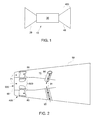
- a turbomachine 10 such as a gas turbine engine
- the turbomachine 10 includes a compressor 20, which is configured to compress inlet gas, a combustor 30 and a turbine section 40.
- the combustor 30 is fluidly coupled to the compressor 20 and thereby receptive of the compressed gas from the compressor 20.
- the compressed gas is mixed with fuel and combusted to produce high temperature fluids.
- the turbine section 40 is fluidly coupled to the combustor 30 and is configured to thereby receive the high temperature fluids produced in the combustor 30.
- the turbine section 40 is configured to generate mechanical energy from the received high temperature fluids produced by the combustion and includes an exhaust gas diffuser 400.
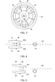
- the exhaust gas diffuser 400 includes a peripheral body 50, which may be annular and/or divergent in shape, and a center body 60.
- the center body 60 may also be annular in shape and is formed to define an interior 600 therein.
- the center body 60 is disposed within the peripheral body 50 to define an annulus 70 between an interior surface of the peripheral body 50 and an exterior surface of the center body 60. This annulus 70 is formed to define a pathway along which a first fluid 71 may be directed to flow along a main flow direction.
- the exhaust gas diffuser 400 further includes a plurality of first members 80 and a plurality of second members 90.
- the plurality of the first members 80 are provided as, for example, struts extending from the peripheral body 50 to the center body 60.
- the plurality of the first members 80 are each respectively coupled to the peripheral body 50 and to the center body 60 to support the center body 60 within the peripheral body 50.
- the plurality of the first members 80 may be arranged in a circumferential array about the center body 60, with each first member 80 being angularly distant from adjacent first members 80 at uniform and/or non-uniform angular distances.
- the plurality of the second members 90 are provided as, for example, manways extending from the peripheral body 50 to the center body 60.
- the plurality of the second members 90 are each configured to extend across the annulus 70 from the peripheral body 50 to the center body 60 and may be disposed at respective axial locations that are downstream from the plurality of the first members 80 relative to the flow of the first fluid 71 along the main flow direction.
- the plurality of the second members 90 may be configured to transport a second fluid 91 from an exterior of the peripheral body 50 to the interior 600 of the center body 60.
- the plurality of the second members 90 may also be coupled to the peripheral body 50 and to center body 60 to support the center body 60 within the peripheral body 50.
- the plurality of the second members 90 may also be arranged in a circumferential array about the center body 60, with each second member 90 being angularly distant from adjacent second members 90 at uniform and/or non-uniform angular distances.
- each one of the plurality of the first members 80 includes a trailing edge 800 that generates a wake due to interference thereof with the flow of the first fluid 71.
- This wake is a low momentum, weak flow that continuously diffuses along a length of the exhaust gas diffuser 400 toward the plurality of the second members 90. Since each of the plurality of the second members 90 is normally relatively wide as compared to the first members 80, interactions between the wake and the plurality of the second members 90 can lead to wakes generated by the plurality of the second members 90 of significantly increased size that lead to further disturbances in the flow of the first fluid 71.
- the plurality of the second members 90 may be circumferentially clocked relative to the plurality of the first members 80 such that the wake generated by the respective trailing edges 800 of the first members 80 can be directed to avoid hitting the plurality of the second members 90 at least in part.
- the plurality of the first members 80 may be provided as eight (8) first members 80 with substantially uniform angular distance between adjacent first members 80 while the plurality of the second members 90 may be provided as three (3) second members 90. Of these three second members 90, each one is circumferentially clocked at about a circumferential midway (or 50%) between adjacent first members 80 with an angular tolerance of about ⁇ 5 degrees.
- the wake generated by the trailing edges 800 will tend to avoid hitting the plurality of the second members 90 at least in part.
- the plurality of the second members 90 will therefore see high momentum, strong flow and will, therefore, tend to generate relatively smaller wakes then they otherwise would. This may aid in overall flow mixing and improved performance of the exhaust gas diffuser 400.
- first and second members 80 and 90 are described above as having eight first members 80 and three second members 90, it is to be understood that this configuration is merely exemplary and that more or less first members 80 or second members 90 may be provided. In any case, the circumferential clocking of the second members 90 may be maintained to the degree made possible by the numbers of the first and second members 80 and 90.
- each of the plurality of the first members 80 may include symmetrically disposed struts 81 that direct the flow of the first fluid 71 downstream in alignment with a centerline 100 of the turbomachine 10 (see FIG. 4 ).
- each of the plurality of the first members 80 may include cambered struts 82 that direct the flow of the first fluid 71 downstream at an angle relative to the centerline 100.
- the circumferential clocking of the corresponding one of the plurality of the second members 90 may be adjusted such that the second member 90 is circumferentially clocked at about a circumferential midway (or 50%) between adjacent first members 80 with an angular tolerance of about ⁇ 5 degrees.
- each one or more of the plurality of the second members 90 may have an oval-shaped cross-section 901 (see FIG. 6 ), a circular cross-section 902 (see FIG. 7 ) or an airfoil-shaped cross-section 903 (see FIG. 8 ).
- Each one of the various shapes of the plurality of the second members 90 may be provided to each of the second members 90 or in combination with one or more of the other various shapes.
- the plurality of the first members 80 is symmetric
- the plurality of the second members 90 may be symmetric or cambered.
- the plurality of the first members 80 is cambered
- the plurality of the second members 90 may be symmetric or cambered.
- each one of the plurality of the second members 90 may include at least one or both of an upstream vortex breaker 910 and a downstream vortex breaker 911.
- the upstream and downstream vortex breakers 910 and 911 are disposed forward and aft of the one of the second members 90 to which they are associated, respectively, may be circumferentially clocked in correspondence with the one of the second members 90 to which they are associated.
- the peripheral body 50 may be formed to include a Carnot section 501.
- the Carnot section 501 is characterized as a narrowing of the diffuser flow area from a first axial location to a second axial location downstream from the first axial location.
- the Carnot section 501 in this case may be substantially axially aligned with the plurality of the second members 90.
Landscapes
- Engineering & Computer Science (AREA)
- Mechanical Engineering (AREA)
- General Engineering & Computer Science (AREA)
- Physics & Mathematics (AREA)
- Fluid Mechanics (AREA)
- Structures Of Non-Positive Displacement Pumps (AREA)
Applications Claiming Priority (1)
| Application Number | Priority Date | Filing Date | Title |
|---|---|---|---|
| US13/275,040 US20130091865A1 (en) | 2011-10-17 | 2011-10-17 | Exhaust gas diffuser |
Publications (1)
| Publication Number | Publication Date |
|---|---|
| EP2584155A2 true EP2584155A2 (de) | 2013-04-24 |
Family
ID=47115375
Family Applications (1)
| Application Number | Title | Priority Date | Filing Date |
|---|---|---|---|
| EP12188727.7A Withdrawn EP2584155A2 (de) | 2011-10-17 | 2012-10-16 | Abgasdiffusor |
Country Status (3)
| Country | Link |
|---|---|
| US (1) | US20130091865A1 (de) |
| EP (1) | EP2584155A2 (de) |
| CN (1) | CN103046975A (de) |
Cited By (2)
| Publication number | Priority date | Publication date | Assignee | Title |
|---|---|---|---|---|
| WO2015142200A1 (en) * | 2014-03-18 | 2015-09-24 | General Electric Company | Exhaust gas diffuser with main struts and small struts |
| DE102023205775A1 (de) * | 2023-06-21 | 2024-12-24 | Siemens Energy Global GmbH & Co. KG | Gasturbine und Verfahren zur Verbesserung einer Gasturbine |
Families Citing this family (7)
| Publication number | Priority date | Publication date | Assignee | Title |
|---|---|---|---|---|
| DE102011118735A1 (de) * | 2011-11-17 | 2013-05-23 | Alstom Technology Ltd. | Diffusor, insbesondere für eine axiale strömungsmaschine |
| PL221113B1 (pl) * | 2012-01-25 | 2016-02-29 | Gen Electric | Układy dyfuzora wydechowego turbiny |
| US10151325B2 (en) * | 2015-04-08 | 2018-12-11 | General Electric Company | Gas turbine diffuser strut including a trailing edge flap and methods of assembling the same |
| US10563543B2 (en) | 2016-05-31 | 2020-02-18 | General Electric Company | Exhaust diffuser |
| CN210599175U (zh) * | 2018-07-13 | 2020-05-22 | 博格华纳公司 | 涡轮机扩散器 |
| KR102403823B1 (ko) * | 2019-12-13 | 2022-05-30 | 두산에너빌리티 주식회사 | 스트립이 형성된 배기 디퓨져의 스트롯 구조 및 가스터빈 |
| CN114687817B (zh) * | 2020-12-29 | 2024-09-06 | 上海电气燃气轮机有限公司 | 一种中心体、排气扩散器、燃气轮机和联合循环电站 |
Family Cites Families (11)
| Publication number | Priority date | Publication date | Assignee | Title |
|---|---|---|---|---|
| US3734639A (en) * | 1968-01-25 | 1973-05-22 | Gen Motors Corp | Turbine cooling |
| EP0035838B1 (de) * | 1980-03-10 | 1985-02-06 | Rolls-Royce Plc | Diffusor |
| CH672004A5 (de) * | 1986-09-26 | 1989-10-13 | Bbc Brown Boveri & Cie | |
| DE59204947D1 (de) * | 1992-08-03 | 1996-02-15 | Asea Brown Boveri | Mehrzoniger Diffusor für Turbomaschine |
| US5813828A (en) * | 1997-03-18 | 1998-09-29 | Norris; Thomas R. | Method and apparatus for enhancing gas turbo machinery flow |
| DE19805115A1 (de) * | 1998-02-09 | 1999-08-19 | Siemens Ag | Abgasdiffusor |
| FR2835019B1 (fr) * | 2002-01-22 | 2004-12-31 | Snecma Moteurs | Diffuseur pour moteur a turbine a gaz terrestre ou aeronautique |
| US6866479B2 (en) * | 2003-05-16 | 2005-03-15 | Mitsubishi Heavy Industries, Ltd. | Exhaust diffuser for axial-flow turbine |
| JP4040556B2 (ja) * | 2003-09-04 | 2008-01-30 | 株式会社日立製作所 | ガスタービン設備及び冷却空気供給方法 |
| KR101245084B1 (ko) * | 2008-02-27 | 2013-03-18 | 미츠비시 쥬고교 가부시키가이샤 | 배기실의 연결 구조 및 터빈의 지지 구조 그리고 가스 터빈 |
| US9115602B2 (en) * | 2011-10-19 | 2015-08-25 | Siemens Aktiengesellschaft | Exhaust diffuser including flow mixing ramp for a gas turbine engine |
-
2011
- 2011-10-17 US US13/275,040 patent/US20130091865A1/en not_active Abandoned
-
2012
- 2012-10-16 EP EP12188727.7A patent/EP2584155A2/de not_active Withdrawn
- 2012-10-17 CN CN2012103938861A patent/CN103046975A/zh active Pending
Non-Patent Citations (1)
| Title |
|---|
| None |
Cited By (3)
| Publication number | Priority date | Publication date | Assignee | Title |
|---|---|---|---|---|
| WO2015142200A1 (en) * | 2014-03-18 | 2015-09-24 | General Electric Company | Exhaust gas diffuser with main struts and small struts |
| US10392975B2 (en) | 2014-03-18 | 2019-08-27 | General Electric Company | Exhaust gas diffuser with main struts and small struts |
| DE102023205775A1 (de) * | 2023-06-21 | 2024-12-24 | Siemens Energy Global GmbH & Co. KG | Gasturbine und Verfahren zur Verbesserung einer Gasturbine |
Also Published As
| Publication number | Publication date |
|---|---|
| US20130091865A1 (en) | 2013-04-18 |
| CN103046975A (zh) | 2013-04-17 |
Similar Documents
| Publication | Publication Date | Title |
|---|---|---|
| EP2584155A2 (de) | Abgasdiffusor | |
| US20140260283A1 (en) | Gas turbine engine exhaust mixer with aerodynamic struts | |
| US8967959B2 (en) | Turbine of a turbomachine | |
| US20120034064A1 (en) | Contoured axial-radial exhaust diffuser | |
| US8757969B2 (en) | Turbine exhaust plenum | |
| US9689312B2 (en) | Gas turbine engine component | |
| US9528440B2 (en) | Gas turbine exhaust diffuser strut fairing having flow manifold and suction side openings | |
| US20100239418A1 (en) | Compressor diffuser | |
| US20150098812A1 (en) | Integrated strut and turbine vane nozzle arrangement | |
| US20150345301A1 (en) | Rotor blade cooling flow | |
| US20120304652A1 (en) | Injector apparatus | |
| JP6386716B2 (ja) | ターボ機械における関節式トランジションダクト | |
| US11415079B2 (en) | Turbo-shaft ejector with flow guide ring | |
| US10550729B2 (en) | Asymmetric gas turbine exhaust diffuser | |
| EP2581664A1 (de) | Ringförmiges Strömungsbedingungselement für eine Gasturbomaschine-Brenneranordnung | |
| EP2543850A1 (de) | Anordnung zur Halterung einer Turbinenbaugruppe und zugehörige Turbinenbaugruppe | |
| JP5816264B2 (ja) | フロースプリッタを備える圧縮器排出ケーシングを有するガスタービンエンジン | |
| EP2578809A3 (de) | Turbomaschine mit einem aeromechanischen System zur Strömungsbeeinflussung und Verfahren zum Betrieb | |
| US20190353054A1 (en) | Exhaust system for a gas turbine engine | |
| WO2016068862A1 (en) | Gas turbine engine | |
| KR20170010044A (ko) | 공기유도부재가 마련된 배기 후드를 포함하는 가스 터빈 | |
| US20180258778A1 (en) | Non-axially symmetric transition ducts for combustors | |
| KR20170007871A (ko) | 공기유도부재가 마련된 배기 후드를 포함하는 가스 터빈 |
Legal Events
| Date | Code | Title | Description |
|---|---|---|---|
| PUAI | Public reference made under article 153(3) epc to a published international application that has entered the european phase |
Free format text: ORIGINAL CODE: 0009012 |
|
| AK | Designated contracting states |
Kind code of ref document: A2 Designated state(s): AL AT BE BG CH CY CZ DE DK EE ES FI FR GB GR HR HU IE IS IT LI LT LU LV MC MK MT NL NO PL PT RO RS SE SI SK SM TR |
|
| AX | Request for extension of the european patent |
Extension state: BA ME |
|
| STAA | Information on the status of an ep patent application or granted ep patent |
Free format text: STATUS: THE APPLICATION IS DEEMED TO BE WITHDRAWN |
|
| 18D | Application deemed to be withdrawn |
Effective date: 20160503 |