EP2584200B1 - Valve d'entrée de gaz pour un compresseur, compresseur équipé d'une telle valve d'entrée de gaz et procédé de fonctionnement d'un compresseur équipé d'une telle valve d'entrée de gaz - Google Patents
Valve d'entrée de gaz pour un compresseur, compresseur équipé d'une telle valve d'entrée de gaz et procédé de fonctionnement d'un compresseur équipé d'une telle valve d'entrée de gaz Download PDFInfo
- Publication number
- EP2584200B1 EP2584200B1 EP12189089.1A EP12189089A EP2584200B1 EP 2584200 B1 EP2584200 B1 EP 2584200B1 EP 12189089 A EP12189089 A EP 12189089A EP 2584200 B1 EP2584200 B1 EP 2584200B1
- Authority
- EP
- European Patent Office
- Prior art keywords
- valve
- piston
- gas inlet
- compressor
- section
- Prior art date
- Legal status (The legal status is an assumption and is not a legal conclusion. Google has not performed a legal analysis and makes no representation as to the accuracy of the status listed.)
- Active
Links
Images


Classifications
-
- F—MECHANICAL ENGINEERING; LIGHTING; HEATING; WEAPONS; BLASTING
- F04—POSITIVE - DISPLACEMENT MACHINES FOR LIQUIDS; PUMPS FOR LIQUIDS OR ELASTIC FLUIDS
- F04C—ROTARY-PISTON, OR OSCILLATING-PISTON, POSITIVE-DISPLACEMENT MACHINES FOR LIQUIDS; ROTARY-PISTON, OR OSCILLATING-PISTON, POSITIVE-DISPLACEMENT PUMPS
- F04C29/00—Component parts, details or accessories of pumps or pumping installations, not provided for in groups F04C18/00 - F04C28/00
- F04C29/12—Arrangements for admission or discharge of the working fluid, e.g. constructional features of the inlet or outlet
- F04C29/124—Arrangements for admission or discharge of the working fluid, e.g. constructional features of the inlet or outlet with inlet and outlet valves specially adapted for rotary or oscillating piston pumps
- F04C29/126—Arrangements for admission or discharge of the working fluid, e.g. constructional features of the inlet or outlet with inlet and outlet valves specially adapted for rotary or oscillating piston pumps of the non-return type
-
- F—MECHANICAL ENGINEERING; LIGHTING; HEATING; WEAPONS; BLASTING
- F04—POSITIVE - DISPLACEMENT MACHINES FOR LIQUIDS; PUMPS FOR LIQUIDS OR ELASTIC FLUIDS
- F04C—ROTARY-PISTON, OR OSCILLATING-PISTON, POSITIVE-DISPLACEMENT MACHINES FOR LIQUIDS; ROTARY-PISTON, OR OSCILLATING-PISTON, POSITIVE-DISPLACEMENT PUMPS
- F04C28/00—Control of, monitoring of, or safety arrangements for, pumps or pumping installations specially adapted for elastic fluids
- F04C28/06—Control of, monitoring of, or safety arrangements for, pumps or pumping installations specially adapted for elastic fluids specially adapted for stopping, starting, idling or no-load operation
-
- F—MECHANICAL ENGINEERING; LIGHTING; HEATING; WEAPONS; BLASTING
- F04—POSITIVE - DISPLACEMENT MACHINES FOR LIQUIDS; PUMPS FOR LIQUIDS OR ELASTIC FLUIDS
- F04C—ROTARY-PISTON, OR OSCILLATING-PISTON, POSITIVE-DISPLACEMENT MACHINES FOR LIQUIDS; ROTARY-PISTON, OR OSCILLATING-PISTON, POSITIVE-DISPLACEMENT PUMPS
- F04C28/00—Control of, monitoring of, or safety arrangements for, pumps or pumping installations specially adapted for elastic fluids
- F04C28/24—Control of, monitoring of, or safety arrangements for, pumps or pumping installations specially adapted for elastic fluids characterised by using valves controlling pressure or flow rate, e.g. discharge valves or unloading valves
-
- F—MECHANICAL ENGINEERING; LIGHTING; HEATING; WEAPONS; BLASTING
- F04—POSITIVE - DISPLACEMENT MACHINES FOR LIQUIDS; PUMPS FOR LIQUIDS OR ELASTIC FLUIDS
- F04C—ROTARY-PISTON, OR OSCILLATING-PISTON, POSITIVE-DISPLACEMENT MACHINES FOR LIQUIDS; ROTARY-PISTON, OR OSCILLATING-PISTON, POSITIVE-DISPLACEMENT PUMPS
- F04C28/00—Control of, monitoring of, or safety arrangements for, pumps or pumping installations specially adapted for elastic fluids
- F04C28/24—Control of, monitoring of, or safety arrangements for, pumps or pumping installations specially adapted for elastic fluids characterised by using valves controlling pressure or flow rate, e.g. discharge valves or unloading valves
- F04C28/26—Control of, monitoring of, or safety arrangements for, pumps or pumping installations specially adapted for elastic fluids characterised by using valves controlling pressure or flow rate, e.g. discharge valves or unloading valves using bypass channels
-
- F—MECHANICAL ENGINEERING; LIGHTING; HEATING; WEAPONS; BLASTING
- F04—POSITIVE - DISPLACEMENT MACHINES FOR LIQUIDS; PUMPS FOR LIQUIDS OR ELASTIC FLUIDS
- F04C—ROTARY-PISTON, OR OSCILLATING-PISTON, POSITIVE-DISPLACEMENT MACHINES FOR LIQUIDS; ROTARY-PISTON, OR OSCILLATING-PISTON, POSITIVE-DISPLACEMENT PUMPS
- F04C29/00—Component parts, details or accessories of pumps or pumping installations, not provided for in groups F04C18/00 - F04C28/00
- F04C29/12—Arrangements for admission or discharge of the working fluid, e.g. constructional features of the inlet or outlet
- F04C29/124—Arrangements for admission or discharge of the working fluid, e.g. constructional features of the inlet or outlet with inlet and outlet valves specially adapted for rotary or oscillating piston pumps
-
- F—MECHANICAL ENGINEERING; LIGHTING; HEATING; WEAPONS; BLASTING
- F04—POSITIVE - DISPLACEMENT MACHINES FOR LIQUIDS; PUMPS FOR LIQUIDS OR ELASTIC FLUIDS
- F04C—ROTARY-PISTON, OR OSCILLATING-PISTON, POSITIVE-DISPLACEMENT MACHINES FOR LIQUIDS; ROTARY-PISTON, OR OSCILLATING-PISTON, POSITIVE-DISPLACEMENT PUMPS
- F04C18/00—Rotary-piston pumps specially adapted for elastic fluids
- F04C18/08—Rotary-piston pumps specially adapted for elastic fluids of intermeshing-engagement type, i.e. with engagement of co-operating members similar to that of toothed gearing
- F04C18/12—Rotary-piston pumps specially adapted for elastic fluids of intermeshing-engagement type, i.e. with engagement of co-operating members similar to that of toothed gearing of other than internal-axis type
- F04C18/14—Rotary-piston pumps specially adapted for elastic fluids of intermeshing-engagement type, i.e. with engagement of co-operating members similar to that of toothed gearing of other than internal-axis type with toothed rotary pistons
- F04C18/16—Rotary-piston pumps specially adapted for elastic fluids of intermeshing-engagement type, i.e. with engagement of co-operating members similar to that of toothed gearing of other than internal-axis type with toothed rotary pistons with helical teeth, e.g. chevron-shaped, screw type
-
- F—MECHANICAL ENGINEERING; LIGHTING; HEATING; WEAPONS; BLASTING
- F04—POSITIVE - DISPLACEMENT MACHINES FOR LIQUIDS; PUMPS FOR LIQUIDS OR ELASTIC FLUIDS
- F04C—ROTARY-PISTON, OR OSCILLATING-PISTON, POSITIVE-DISPLACEMENT MACHINES FOR LIQUIDS; ROTARY-PISTON, OR OSCILLATING-PISTON, POSITIVE-DISPLACEMENT PUMPS
- F04C2270/00—Control; Monitoring or safety arrangements
- F04C2270/58—Valve parameters
Definitions
- the present invention relates to a gas inlet valve for a compressor, in particular for a rotary compressor, to a compressor, in particular a rotary compressor, with such a gas inlet valve and to a method for operating a compressor, in particular a rotary compressor, with such a gas inlet valve.
- a compressor is usually directly coupled or driven by a force converter via a gear and compresses a medium, in particular a gas, preferably air, as soon as the compressor is set in motion.
- a medium in particular a gas, preferably air
- this function has some disadvantages for the installation of a compressed air network.
- compressed air is used for a wide variety of applications. Depending on the number of consumers connected to the compressed air network, the compressed air requirement increases or decreases. In order to maintain the required pressure level, the compressor would therefore be constantly alternating between full load and standstill. Such a regulation would be at the expense of the service life of all driven and driving components.
- there is the increased power consumption in the start-up phase which also has an impact on the operating costs.
- a control unit in a so-called screw compressor can be a so-called gas inlet valve. This is connected upstream of the compressor block.
- the gas inlet valve should enable a check function, which prevents gas and/or fluid from flowing back from the compressor into the compressor's surroundings, idle control, full load control and/or proportional control.
- the gas inlet valve may only let a certain amount of air or process gas into the compressor. This measure can be explained as follows: Due to the inertia of the moving components, the start-up of the compressor requires an increased amount of energy compared to full-load operation. In order to minimize these load peaks, it helps to minimize the work that is done when compressing the medium by reducing the supply air flow to a minimum amount.
- the gas inlet valve has a spring-loaded valve body. To switch from idle operation to full-load operation, this is lifted off the valve seat by means of a pressurized piston against the spring force of a spring that presses the valve body against its valve seat.
- the DE 603 07 662 T2 a gas inlet valve in which such a large-dimensioned valve spring is dispensable.
- a double piston that can be pressurized on both sides is pressurized on the side facing away from the gas outlet of the gas inlet valve with the negative pressure at the gas outlet of the gas inlet valve and on the opposite side with a control pressure in order to press the valve body against its valve seat.
- this requires a complex and finely tuned pneumatic system that is therefore prone to errors in order to ensure that the gas inlet valve functions reliably.
- the DE 689 04 263 T2 describes a screw-type vacuum pump comprising a pump housing having suction and discharge ports on opposite sides thereof; intermeshing outer and inner rotors comprising means for pumping a gas from the suction port when the rotors are rotated; power transmission means for rotating the rotors comprising a gear box having an oil reservoir; oil circulation means comprising an oil pump and an oil cooler for circulating lubricating oil to the pump housing for lubricating the rotors; and a shut-off valve fluidly connected to the suction port and comprising a valve housing defining a gas flow space and a cylinder space, the gas flow space being fluidly separated from the cylinder space insulated and having a valve seat, and a valve body which is normally pressed into the closed position to close the valve seat and seal the suction opening, the valve body enclosing a piston fitted into the cylinder space to separate the cylinder space into an oil chamber and an air chamber at atmospheric pressure, a three-way changeover valve being provided which
- the DE 603 07 662 T2 describes a compressor comprising a compressor element provided with a rotor chamber to which an inlet pipe and an outlet pipe are connected, a container in the outlet pipe and a pressure control system comprising an inlet valve arranged in the inlet pipe, a piston connected to the inlet pipe and movable in a cylinder, a bypass bypassing said inlet valve and wherein, between the inlet pipe and the rotor chamber, a gas flow restrictor and a non-return valve are arranged in succession, allowing only gas into the rotor chamber, and a gas pipe connecting the container to the part of the bypass arranged between the gas flow restrictor and the non-return valve, and a relief valve arranged in said gas pipe.
- the EN 602 10 088 T2 describes a volumetric compressor comprising a compressor element with a compression chamber to which an inlet line which can be closed off by means of an inlet valve, and a pressure line in which a pressure vessel is installed, the inlet valve comprising a valve element which cooperates with a valve seat, said element being connected to a piston which can be displaced in a cavity in a cylinder-forming housing, and a resilient element which presses this valve element towards the valve seat, while a control line connects the interior of the pressure vessel with a cylinder chamber formed between the effective side of the piston and the housing.
- the US 6 431 210 B1 describes an inlet valve for a gas compressor, wherein the inlet valve has a piston movable in a housing chamber, which can be moved towards and away from a housing inlet.
- a valve disc can be moved with the piston, wherein the valve disc has an opening for controlling an air flow from the housing inlet into the housing chamber.
- the inlet valve has a flexible component which cooperates with the valve disc to close the opening.
- the GB385801A describes an arrangement for automatically starting up a compressor, especially for starting up without a load.
- a start valve leaves the suction line in a closed state.
- the start valve is kept in its closed operating state by a spring.
- the valve opens when the compressor is in operation because the resulting negative pressure acts directly on the valve.
- the US 5 848 608 A describes an exhaust valve in which a secondary valve seat and a secondary valve body, which form a secondary valve mechanism for restrictively opening a channel, are incorporated into a primary valve body in a primary valve mechanism.
- the US 2011/220214 A1 describes a valve actuation assembly consisting of a valve and a pneumatic or hydraulic actuator, in which a connection which transmits the pressure of a working fluid acting on the valve surface to a counter-bias chamber in an actuator housing is defined axially through the valve and the actuator.
- the object of the present invention is to eliminate the above-mentioned disadvantages and to provide a gas inlet valve which is improved compared to the prior art.
- a gas inlet valve for a compressor, in particular for a rotary compressor, comprising: a housing which has a gas inlet section for sucking in a gas and a gas outlet section for guiding the sucked-in gas to a compressor block of the compressor, which can be fluidically connected to the gas inlet section as required; a valve device arranged between the gas inlet section and the gas outlet section with a valve body and with a valve seat, wherein the valve body is in a closed Operating state of the valve device rests sealingly on the valve seat, and wherein the valve body is lifted off the valve seat in an open operating state of the valve device; a piston device which has a first piston section and a second piston section which differs from the first piston section, wherein the first piston section is displaceably guided in a first cylinder section of the housing and the second piston section is displaceably guided in a second cylinder section of the housing which differs from the first cylinder section, wherein the first cylinder section has a diameter DZ1, the second
- a compressor in particular a rotary compressor, with such a gas inlet valve is provided.
- a method for operating a compressor, in particular a rotary compressor, with a gas inlet valve comprising the following method steps: starting a drive motor of the compressor and generating a negative pressure in the gas outlet section of the gas inlet valve, the valve device being closed; pressure-controlled opening of the bridging device by means of the negative pressure prevailing in the gas outlet section for guiding the sucked-in gas via the bridging device from the gas inlet section to the gas outlet section; compressing the sucked-in gas in the compressor block; releasing a working pressure supply line between a pressure chamber of the compressor and a second cylinder chamber of the gas inlet valve; and opening the valve device by means of the pressurized second cylinder chamber.
- the idea underlying the present invention is to design the piston device with a first piston section and with a second piston section that differs from the first piston section.
- the first cylinder chamber is always subjected to the gas pressure present in the gas outlet section via the fluid line.
- the valve body is coupled to the piston device via the piston rod, the valve body is pressed against its valve seat in the idle operating state in which a negative pressure prevails in the gas outlet section.
- a powerfully dimensioned valve spring for implementing the idle operating state is therefore Furthermore, only the second cylinder chamber needs to be subjected to working pressure to open the valve device. A complex and finely tuned pneumatic system is therefore not necessary for the gas inlet valve to function reliably.
- the piston rod has the fluid line, wherein the fluid line is designed in particular as a fluid channel running in the piston rod.
- the fluid line is preferably designed as a through-hole running centrally in the piston rod.
- the fluid line is designed as a fluid channel running in the housing, in particular in a wall of the housing.
- the latter has a spring device which pre-tensions the piston device in the direction of a housing cover of the housing.
- the spring device is arranged between the piston device and a counter surface of the housing (valve dome), wherein the spring device presses the valve body via the mechanical Coupling of the piston device and the valve body by means of the piston rod spring-loaded against its valve seat. This ensures that the valve device is completely closed when the compressor is at a standstill. This makes it possible to position the movable components of the gas inlet valve vertically, thereby reducing wear on the bearing points.
- the spring device is designed to bear at least a dead weight of the piston device and the piston rod.
- the spring device can be designed to additionally bear a dead weight of the valve body and/or a spring of the valve device.
- a spring device with a low spring stiffness can be selected and mounted with a low spring preload. This simplifies the assembly of the spring device.
- the gas inlet valve has a bridging device which, as required, in particular in an idle operating state of the gas inlet valve, fluidically connects the gas inlet section to the gas outlet section by bridging the closed valve device, wherein the bridging device is preferably designed to work according to the principle of a check valve.
- the bridging device In the idle operating state, a required (small) idle air quantity is sucked in via the bridging device. This enables the supply of a reduced supply air flow when the compressor is idling with a simple technical measure. This simplifies the structure of the gas inlet valve.
- an effective area of the first piston section is larger than an effective area of the second piston section.
- the effective area of the first piston section is preferably at least 15 times larger than the effective area of the second piston section.
- the effective area of the first piston section is 30 times larger than the effective area of the second piston section.
- the effective area of the first piston section corresponds to 0.7 to 1.5 times, in particular 1 to 1.1 times, an effective area of the valve body.
- the effective area of the first piston section preferably corresponds to 1.05 times the effective area of the valve body.
- an effective surface of the first piston section and an effective surface of the valve body are dimensioned such that the valve device, when the second cylinder chamber is vented, remains in its closed operating state regardless of the operating state of the compressor as a result of forces acting on the first piston section and the valve body and as a result of a spring force of the spring device acting on the valve body.
- the compressor can, for example, be in a load, idle or standstill operating state.
- the valve device can be opened only by applying a control pressure to the second cylinder chamber. As a result, the Valve device in a vented state of the second cylinder chamber always in its closed operating state.
- the valve body is slidably mounted on the piston rod.
- a pressure builds up below the valve body with a time delay (backflow).
- the valve body is slidably mounted on the piston rod, it is raised in the direction of the valve seat over its entire stroke in fractions of a second due to the prevailing pressure in the gas outlet section and pressed against the valve seat of the valve device. This creates a check function that reliably prevents gas and/or oil from flowing back from the gas outlet section into the gas inlet section.
- the valve device has a spring which is arranged between a limiting element of the piston rod and the valve body.
- the spring is designed to bear the weight of the valve body.
- the piston device is moved against a spring force of the spring device when the valve device is opened.
- an effective surface of the first piston section and an effective surface of the valve body are dimensioned such that the valve device remains in its closed operating state when the second cylinder chamber is vented, regardless of an operating state of the compressor, as a result of forces acting on the first piston section and the valve body and as a result of a spring force of the spring device acting on the valve body, and that the valve device is only opened by applying a control pressure to the second cylinder chamber.
- the valve device is always brought into its closed operating state when the second cylinder chamber is vented.
- the Figure 1 illustrates a preferred embodiment of a gas inlet valve 1 for a compressor, in particular for a rotary compressor.
- the compressor is designed as a screw compressor, multi-cell compressor, scroll compressor or the like, which is preferably driven by an electric or internal combustion engine.
- the compressor can, for example, be designed to be fluid-lubricated or dry-running.
- the compressor preferably has a pressure chamber which is connected downstream of a compressor block of the compressor.
- the pressure chamber can be Fluid separation tank, in particular as an oil separation tank or as a water separation tank.
- the pressure chamber can be designed, for example, as a section of a pipeline downstream of the first compressor stage.
- the preferred embodiment of the gas inlet valve 1 is explained here with reference to an oil-injected screw compressor.
- the gas inlet valve 1 described below is not limited to such compressors, however, but can be used with any type of compressor.
- the gas inlet valve 1 has a housing 2 with a gas inlet section 3 and a gas outlet section 4.
- the gas inlet section 3 is designed to suck in a gas, for example ambient air.
- the gas can be uncompressed or already pre-compressed.
- the gas outlet section 4 is designed to forward the gas sucked in by means of the gas inlet section 3 to a compressor block 5 of the compressor.
- the gas inlet section 3 and the gas outlet section 4 can be fluidically separated from one another or fluidically connected to one another as required by means of a valve device 6 arranged between the gas inlet section 3 and the gas outlet section 4.
- the housing 2 preferably has a first hollow-cylindrical housing section 7.
- the valve device 6 is preferably arranged at a first end section of the first housing section 7.
- the first housing section 7 has a block connection flange 8 with a substantially annular screw-on surface 9.
- the screw-on surface 9 preferably lies flat on the compressor block 5.
- the Block connection flange 8 is connected to the compressor block 5 in a force-locking and/or form-locking manner.
- a sealing device for example an O-ring, is preferably arranged between the screw-on surface 9 and the compressor block 5.
- the connecting elements are designed as screws, for example.
- the screw-on surface 9 forms, for example, an x/y plane of the first housing section 7 or the housing 2, to which a z-axis or vertical direction of the housing 2 is positioned perpendicularly.
- a central axis 10 of the first housing section 7 or the housing 2 preferably runs in the z-direction.
- the central axis 10 can alternatively be arranged at an angle of approximately 45° to 90° to the screw-on surface 9.
- Other installation positions of the compressor block or the screw-on surface are also conceivable.
- the screw-on surface 9 can be arranged at any position of the first housing section 7 and/or at any angle to the central axis 10 of the first housing section 7.
- the first housing section 7 further comprises an optional hollow cylindrical cast eye 11 which is formed integrally with the first housing section 7 and is preferably arranged in a lower region of the first cylinder section 7, i.e. in the region associated with the gas outlet section 4.
- the cast eye 11 can alternatively be arranged at any position on the housing 2.
- a central axis 12 of the cast eye 11 is preferably arranged substantially perpendicular to the central axis 10 of the housing 2.
- the cast eye 11 is preferably provided with a central stepped bore 13 which runs along the central axis 12 and which penetrates the first cylinder section 7 and connects the gas inlet section 3 to the surroundings 14 of the inlet valve 1.
- the stepped bore 13 preferably has a larger bore diameter in the cast eye 11 than in the first housing section 7.
- the stepped bore 13 is preferably provided with a valve seat 17 all around.
- the stepped bore 13 is fluidically connected to the gas outlet section 4 by means of a further opening, in particular a bore 18, which runs essentially in the z direction.
- the bridging device 16 preferably has a substantially cylindrical valve piston 19, which is arranged displaceably in the stepped bore 13, and a spring 20, in particular a compression spring 20.
- the valve piston 19 is preferably spring-loaded in the direction of the first housing section 7 by means of the compression spring 20 arranged between the valve piston 19 and the screw plug 15.
- a sealing section 21 of the valve piston 19 rests sealingly against the valve seat 17 of the stepped bore 13 and prevents a gas flow from the gas inlet section 3 to the gas outlet section 4 via the bridging device 16.
- the compression spring 20 is preferably arranged at least in sections in a central recess of the valve piston 19.
- a spring stiffness of the compression spring 20 is preferably designed such that the sealing section 21 is lifted off the valve seat 17 of the stepped bore 13 when a predetermined gas pressure acts against the spring force of the compression spring 20 and thus a gas flow from the Gas inlet section 3 to the gas outlet section 4 via the bridging device 16 is possible.
- the predetermined gas pressure is formed by an overpressure in the gas inlet section 3 compared to the gas outlet section 4. If a gas pressure acts which is less than the predetermined gas pressure, the compression spring 20 presses the sealing section 21 of the valve piston 19 against the valve seat 17.
- the bridging device 16 is in the closed operating state if there is an overpressure in the gas outlet section 4 compared to the gas inlet section 3 or if the gas pressure in the gas outlet section 4 and in the gas inlet section 3 is the same.
- a first cylinder section 22 is provided on a second end section of the first housing section 7 facing away from the first end section.
- the first cylinder section 22 is preferably provided as a machined surface in the hollow cylindrical first housing section 7.
- the first cylinder section 22 preferably has a diameter D Z1 and a length l 1.
- a preferably circumferential shoulder 23 delimits the first cylinder section 22, in particular downwards, i.e. in the direction of the valve device 6.
- the first cylinder section 22 is delimited upwards by a housing cover 24 of the housing 2 which closes off the first housing section 7.
- the housing cover 24 is preferably disk-shaped with a central, approximately cylindrical bulge 25, the central axis of which preferably corresponds to the central axis 10 of the first housing section 7. Alternatively, the bulge 25 can be arranged eccentrically to the central axis 10.
- the housing cover 24 is preferably located in a ring shape on a connecting flange 26 of the first Housing section 7 and is operatively connected to it preferably in a force-fitting and/or form-fitting manner by means of connecting elements, in particular screws.
- the connecting flange 26 To center the housing cover 24 on the connecting flange 26, the latter can preferably have a circumferential centering collar.
- a sealing device for example an O-ring, is preferably provided between the housing cover 24 and the connecting flange 26.
- the housing cover 24 preferably has a cylinder bore which is arranged coaxially to the central axis 10 and extends into the bulge 25, which is designed in particular as a second cylinder section 27 of the gas inlet valve 1.
- the second cylinder section 27 can be designed by means of a bushing, in particular a sliding bushing.
- the second cylinder section 27 preferably penetrates into the housing cover 24 from the side of the first housing section 7 with a depth l 2.
- the second cylinder section 27 of the gas inlet valve 1 has a diameter D Z2 .
- a working pressure supply bore 28 is provided centrally in relation to the cylinder bore, which preferably penetrates the part of the bulge 25 not penetrated by the cylinder bore.
- a second, essentially hollow-cylindrical housing section 29 of the housing 2 is preferably formed integrally with the first housing section 7 and preferably penetrates it at least in sections.
- a central axis 30 of the second housing section 29 is preferably positioned at an angle ⁇ to the central axis 10.
- the angle ⁇ has, for example, a value of approximately 90°, in particular approximately 60°.
- the second housing section 29 is preferably formed such that a first end section of the first housing section 7, which protrudes from the same, is designed as a flange section 31 for connecting a gas supply line to the gas inlet valve 1.
- the gas supply line can be mounted on the flange section 31, for example by means of a clamp.
- a second end section of the second housing section 29 preferably merges into the first end section of the first housing section 7.
- the second housing section 29 is preferably designed, at least in sections, as an intake deflector such that the gas supplied to the housing 2 from the gas inlet section 3 is guided in an arc shape and thus with optimized flow to the gas outlet section 4.
- An upper wall section 32 of the second housing section 29 separates the gas inlet section 3 from an interior space 33 of the first housing section 7.
- a valve dome 34 in particular a cylinder-shaped valve dome, is provided essentially centrally in the housing 2 with a through-hole 35 that is central in relation to the first housing section 7 and runs in the direction of the central axis 10.
- the valve dome 34 is preferably formed integrally with the upper wall section 32.
- a bushing that acts as a sliding bearing can be pressed into the through-hole 35.
- the valve dome 34 serves in particular as a contact surface for a spring device 36 or spring 36, in particular a compression spring 36.
- An opening 37 is preferably provided in the flow shadow of the valve dome 34, which fluidically connects the interior 33 to the gas inlet section 3. Alternatively or additionally, the interior 33 can be fluidically connected directly to the environment 14 by means of an opening.
- the interior 33 and the gas inlet section 3 are always essentially the same gas pressure.
- Essentially the same gas pressure means that slight pressure differences can exist between the interior 33 and the gas inlet section 3.
- the housing 2, ie the housing sections 7, 29 and the housing cover 24 are preferably designed as cast components with machined functional surfaces.
- the housing sections 7, 29 are preferably designed in one piece.
- a piston rod 38 is mounted so as to be displaceable in the z-direction, i.e. along the central axis 10.
- the piston rod 38 is preferably designed as a hollow cylinder with a central fluid line 39 which penetrates the piston rod 38, in particular over its entire length.
- the fluid line 39 is preferably designed as a fluid channel which penetrates the piston rod 38 over its entire length, in particular as a through-bore.
- a first end section 40 of the piston rod 38 is assigned to the gas outlet section 4.
- a second end section 41 of the piston rod 38 faces away from the gas outlet section 4.
- the fluid line 39 is operatively fluidically connected to the gas outlet section 4 in the region of the first end section 40.
- the fluid line 39 can alternatively be designed as a fluid channel running in the housing 2, in particular in a wall of the housing 2.
- the gas inlet valve 1 preferably has a Figure 2 illustrated piston device 42 with a first piston section 43 and with a second piston section 44 that differs from the first piston section 43.
- the first piston section 43 is preferably essentially plate-shaped and is located in particular with the first cylinder section 22 in operative connection.
- the first piston section 43 can preferably slide back and forth along the first cylinder section 22 in the z-direction.
- the maximum path of the first piston section 43 in the direction of the gas outlet section 4 is limited in particular by the shoulder 23.
- the maximum possible path of the first piston section 43 in the direction of the gas outlet section 4 is limited downwards by the valve dome 34 and/or by a shoulder provided on the piston rod 38. This shoulder can, for example, be designed such that it rests against the valve dome 34 to limit the downward path of the first piston section 43.
- the path of the first piston section 43 is limited from the gas outlet section 4 in the direction of the housing cover 24 by the fact that the piston device 42 is coupled to a valve body 57 of the valve device 6 by means of the piston rod 38 operatively connected thereto via its first end section 40.
- the spring device 36 presses the piston device 42 in the direction of the housing cover 24.
- the valve body 57 is spring-loaded against a valve seat 56. Due to the mechanical coupling of the valve body 57 to the piston device 42, it can be achieved by appropriately adjusting the length of the piston rod 42 that the first piston section 43 always has at least a minimal distance from the housing cover 24. Preferably, the first piston section 43 never touches the housing cover 24.
- the first piston section 43 can be provided circumferentially towards the first cylinder section 22 with a first labyrinth seal provided on a circumferential surface 45 of the same. in particular a see-through labyrinth seal.
- the first piston section 43 can be additionally or optionally sealed towards the housing cover 24 by means of a circumferential second labyrinth seal.
- the second labyrinth seal can be designed as a so-called full labyrinth seal, with interlocking labyrinth chambers preferably being incorporated into an end face 46 of the first piston section 43 facing the housing cover 24 and into the housing cover 24.
- the first piston section 43 can alternatively or additionally be sealed against the first cylinder section 22 with an O-ring, piston ring, grooved ring or the like.
- the first piston section 43 has a cylindrical connection section 47 extending in the direction of the valve dome 34 with a central bore 48.
- the bore 48 can alternatively be arranged eccentrically.
- the bore 48 can preferably be provided with an internal thread, which is designed in particular to be complementary to an external thread of the second end section 41 of the piston rod 38.
- the piston rod 38 is firmly connected to the piston device 43 by means of this threaded connection.
- the piston rod 38 can be designed integrally with the piston device 42.
- the essential thing about the connection of the piston rod 38 and the piston device 42 is that the fluid line 39 is fluidically connected to the bore 48.
- the bore 48 can be an integral part of the fluid line 39.
- the spring 36 which is preferably designed as Compression spring 36 is arranged.
- the spring 36 presses the piston device 42, for example with a predetermined spring force, in the direction of the housing cover 24.
- the spring device 36 preloads the valve body 57 of the sealing device 6 against its valve seat 56 via the mechanical coupling of the piston device 42 and the valve body 57 by means of the piston rod 38.
- the first piston section 43 preferably does not touch the housing cover 24.
- the first piston section 43 preferably has a diameter D K1 , which is particularly matched to the diameter D Z1 in such a way that the first piston section 43 can slide in the first cylinder section 22 preferably with little friction, little gas loss and as little play as possible.
- the first piston section 43 preferably forms a first cylinder chamber 49 ( Figure 3 ) of the first cylinder section 22.
- the second piston section 44 is preferably designed as a cylinder coaxial with the first piston section 43.
- the second piston section 44 is a so-called working piston of the gas inlet valve 1.
- the second piston section 44 is arranged in particular on the end face 46 of the first piston section 43 facing away from the connection section 47.
- the piston sections 43, 44 are preferably designed as one piece.
- the second piston section 44 is preferably guided in the second cylinder section 27 so as to be displaceable in the z-direction.
- the first piston section 43 and the second piston section 44 are preferably only displaceable back and forth together in the z-direction.
- the second piston section 44 preferably has a diameter D K2 adapted to the diameter D Z2 of the second cylinder section 27.
- the second piston section 44 is sealed circumferentially from the second cylinder section 27, preferably by means of a sealing ring 51 which is accommodated at least in sections in a circumferential annular groove 50.
- a sealing ring 51 which is accommodated at least in sections in a circumferential annular groove 50.
- a grooved ring, a piston ring or the like can be used instead of the sealing ring 51.
- the second piston section 44 can alternatively be sealed from the second cylinder section 27 using any technical measures in accordance with the first piston section 43.
- the second piston section 44 and the second cylinder section 27 form a second cylinder chamber 52 ( Figure 3 ) of the second cylinder section 27.
- the second cylinder chamber 52 is connected to the working pressure supply bore 28 by means of a working pressure supply line or control line 53 ( Figure 3 ) can be subjected to a working pressure.
- the working pressure supply line 53 is preferably fluidically connected to a pressurized pressure chamber 54 arranged downstream of the compressor block 5. Since the gas inlet valve 1 is explained here with reference to an oil-injected screw compressor, the pressure chamber 54 is preferably designed as an oil separator tank.
- the pressure chamber 54 can be designed as a water separator tank in a water-injected compressor or, in the case of a dry-running compressor, for example as a section of a pipeline downstream of the first compressor stage.
- the interior 33 can optionally be fluidically connected to the oil separator tank. Preferably, a gas pressure prevailing in the oil separator tank is blown off into the interior 33 as required.
- the diameter D K1 of the first piston section 43 is larger than the diameter D K2 of the second piston section 44.
- a pressurizable effective area of the first piston section 43 is larger than a pressurizable effective area of the second piston section 44.
- the effective area of the first piston section 43 is at least 2 times the effective area of the second piston section 44. In particular, the effective area of the first piston section 43 is approximately 6 times the effective area of the second piston section 44.
- the bore 48 of the piston device 42 preferably penetrates the first piston section 43 completely and extends at least partially into the second piston section 44.
- Transverse bores 55 penetrating the second piston section 44 are preferably provided perpendicular to the central axis 10 and in the z-direction above the end face 46, in particular two transverse bores 55 intersecting one another at an angle of approximately 90°, which fluidically connect the bore 48 to the first cylinder chamber 49.
- only one transverse bore 55 or any number, such as three or four transverse bores 55, can be provided. Because the piston rod 38 has the fluid line 39, the first cylinder chamber 49 is always fluidically connected to the gas outlet section 4 via the transverse bores 55, the bore 48 and the fluid line 39, i.e. the gas pressure in the first cylinder chamber 49 is always approximately the same as in the gas outlet section 4.
- the valve device 6 is arranged between the gas inlet section 3 and the gas outlet section 4.
- the valve device 6 has a valve seat 56 with a preferably conical sealing surface, in particular inclined in the direction of the gas inlet section 3.
- the Valve seat 56 is preferably formed integrally with the housing 2.
- a sealing surface of a valve body 57 preferably rests linearly on the valve seat 56. This line is the sealing edge of the valve device 6 and, in the closed operating state of the same, fluidically separates the gas inlet section 3 from the underlying gas outlet section 4.
- the valve body 57 preferably rests on the valve seat 56 from the side of the outlet section 4.
- the sealing device 6 preferably has a sealing diameter D D , which corresponds in particular to the sealing edge.
- the diameter D K1 of the first piston section 43 is preferably larger than the sealing diameter D D .
- a pressurizable effective area of the first piston section 43 is larger than a pressurizable effective area of the valve body 57.
- the effective area of the first piston section 43 is 0.7 to 1.5 times the effective area of the valve body 57.
- the effective area of the first piston section can be 1.05 times the effective area of the valve body 57.
- the valve body 57 is preferably plate-shaped or disk-shaped. In order to obtain a harmonious flow pattern around the valve body 57, the valve body 57 can alternatively have an approximately bell shape, which changes into a conical shape at a lower end facing the gas outlet section 4. A conical angle of the conical shape preferably corresponds to an angle of inclination of the conical sealing surface of the valve seat 56.
- the valve body 57 preferably has a central bore 58 in which an elongated hollow cylindrical bushing, in particular a bearing bush, can be pressed in.
- the valve body 57 is preferably slidably mounted on the first end section 40 of the piston rod 38 by means of a clearance fit.
- the possible mobility of the valve body 57 in the direction of the housing cover 24 is limited upwards by the valve seat 56.
- a limiting element 59 provided on the first end section 40 prevents the valve body 57 from sliding downwards on the piston rod 38 in the direction of the outlet section 4.
- the limiting element 59 can, for example, be designed as a circumferential shoulder on the first end section 40 or as a threaded nut screwed to the first end section 40.
- a spring 60 is arranged between the limiting element 59 and the valve body 57.
- the spring 60 is preferably designed as a compression spring 60.
- the valve body 57 of the valve device 6 is mechanically coupled to the piston device 42 by means of the piston rod 38.
- the piston device 42, the piston rod 38, the spring device 36 and the valve device 6 are arranged in a vertical direction, ie in the z-direction of the gas inlet valve 1.
- the gas pressure in both the gas inlet section 3 and the gas outlet section 4 is essentially the same, for example the ambient pressure.
- the spring 36 is preferably designed such that at least the dead weight of the piston rod 38, the piston device 42, the valve body 57, the spring 60, etc. as well as a spring force F F of the spring 60 acting in the direction of the housing cover 24 are balanced.
- the spring 36 can be designed such that it only balances the dead weight the piston device 42 and the piston rod 38. This means that when the compressor is at a standstill, the gas inlet valve 1 is depressurized, the valve device 6 and the bridging device 16 are closed. Ambient pressure preferably prevails in the cylinder chambers 49, 52.
- the spring 60 is preferably compressed in this operating state such that the valve body 57 rests on the limiting element 59. The force required to compress the spring 60 is provided by the spring 36.
- the Figure 1 illustrates the inlet valve 1 in an idling operating state.
- the valve device 6 is in its closed operating state.
- the valve body 57 preferably rests gas-tight against the valve seat 56.
- the second cylinder chamber 52 is vented, ie there is no gas pressure in it or only ambient pressure.
- a valve 61 ( Figure 3 ), in particular a solenoid valve, which is suitable for fluidically connecting the oil separator container to the second cylinder chamber 52 via the working pressure supply line 53, is preferably closed.
- the valve 61 can alternatively be designed as a pneumatic valve, as any electrically operated valve or the like.
- the working pressure supply line 53 is vented via the valve 61.
- the gas pressure of the gas outlet section 4 also prevails essentially in the first cylinder chamber 49.
- the fluidic connection between the gas outlet section 4 and the first cylinder chamber 49 is realized by the fluid line 39, the bore 48 and the transverse bores 55. This creates a differential pressure between the first cylinder chamber 49 and the interior 33 of the housing 2, which results in a force F O acting upwards in the direction of the housing cover 24.
- the force F O preferably has the same direction of action as the spring force F F.
- the diameter D K1 of the first piston section 43 and the sealing diameter D D or the effective areas of the first piston section 43 and the valve body 57 are preferably coordinated with one another in such a way that a force F R resulting from the forces F U , F O and F F presses the first piston section 43 in the idle operating state of the gas inlet valve 1 in the direction of the housing cover 24.
- a minimum distance between the first piston section 43 and the housing cover 24 also remains when the first piston section 43 has moved as far as possible in the direction of the housing cover 24.
- the resulting force F R is preferably at least large enough that the valve device 6 remains closed in idle. A gas flow from the gas inlet section 3 via the valve device 6 to the gas outlet section 4 is prevented.
- the size of the effective area of the first piston section 43 can be varied within a certain range. in particular by the diameter D K1 of the first piston section 43. A reduction in the effective area of the first piston section 43 can be compensated by increasing the preload of the spring 36.
- the effective area of the first piston section 43 and the effective area of the valve body 57 are dimensioned and/or coordinated with one another in such a way that the force F O acting on the first piston section 43 and the spring force F F of the spring device 36 act against the force F U acting on the valve body 57 in such a way that the valve device 6 remains in its closed operating state when the second cylinder chamber 52 is vented.
- the valve device 6 can therefore only be opened by applying a control pressure to the second cylinder chamber 52.
- the control pressure for controlling the gas inlet valve 1, i.e. for opening the valve device 6 comes from a pressure side of the compressor, i.e. from the pressure chamber 54.
- the valve piston 19 of the bridging device 16 is pressed against the spring preload of the spring 20 in the direction of the screw plug 15.
- a fluidic connection is created between the gas inlet section 3 and the gas outlet section 4 by means of the stepped bore 13 and the bore 18, whereby gas can flow from the gas inlet section 3 around the closed valve device 6 to the gas outlet section 4.
- gas can flow into the compressor block 5.
- the spring 20 is preferably designed or preloaded in such a way that the valve piston 19 is pressed against the spring preload at a predetermined idle differential pressure. Spring force of the spring 20.
- the stepped bore 13, in particular a cross-section of the stepped bore 13, is designed such that a defined amount of gas can flow into the compressor block 5 when the valve piston 19 is moved in the direction of the locking screw 15.
- the gas flowing into the compressor block 5 is compressed and continuously fed to the oil separator tank of the compressor, which is thereby subjected to a gas pressure.
- the oil separator tank is vented into the environment 14 or particularly preferably into the interior 33 by means of a vent valve if necessary in order to prevent an unwanted increase in the gas pressure in the oil separator tank.
- a silencer can be provided in the interior 33, which dampens the noise generated when the gas pressure of the oil separator tank is vented into the interior 33.
- the spring 60 is preferably preloaded by the spring force F F and the force F O , in particular such that the valve body 57 rests on the limiting element 59.
- FIG. 3 An operating state of the gas inlet valve 1 under load or full load is in Figure 3 illustrated.
- the second cylinder chamber 52 is subjected to the gas pressure or working pressure prevailing in the oil separator tank via the working pressure supply line 53.
- the valve device 6 begins to open, ie the valve body 57 is lifted off the valve seat 56.
- the valve body 57 is lifted off the valve seat 56.
- valve device 6 By opening the valve device 6, more gas flows into the compressor block 5, which increases the gas pressure in the oil separator tank and thus the working pressure in the second cylinder chamber 52. This in turn causes the piston device 42 to move further in the direction of the valve dome 34 until the valve device 6 is in its Figure 3 illustrated fully open operating state. In the fully open operating state of the valve device 6, the gas flows unhindered from the gas inlet section 3 to the gas outlet section 4.
- the spring 60 is preferably designed such that it is kept under prestress by the gas flowing through the valve device 6 such that the valve body 57 continues to rest on the limiting element 59.
- the valve 61 is designed as a proportional valve, which variably regulates the working pressure in the second cylinder chamber 52 for the movement of the piston device 42.
- An opening gap that the valve body 57 forms with the valve seat 56 when it lifts off the valve seat 56 can thus be changed as desired. This allows the amount of gas flowing into the compressor block 5 or the delivery amount of the compressor to be regulated. This enables partial load operation of the gas inlet valve 1.
- the Figure 4 illustrates the gas inlet valve 1 in a non-return position. If the compressor is shut down, for example, by an emergency shutdown or idle switch, it takes a certain amount of time until the entire system is vented. This means that the working pressure in the second cylinder chamber 52 still exists even though there is no more gas in the Compressor flows. Furthermore, if the compression process is interrupted, a pressure builds up with a time delay below the valve body 57 in the gas outlet section 4. The flow travels from the intake filter of the compressor through the gas inlet valve 1 to the compressor block 5. Before the returning gas reaches the valve body 57, the spring 60, which is now no longer subjected to gas pressure from the gas inlet section 3, has already raised the valve body almost to the valve seat 59.
- the spring 60 is preferably in a relaxed state. In this operating state, the spring 60 can also be slightly preloaded by the weight of the valve body 57.
- the check function occurs, ie when the returning gas reaches the valve body 57, the path of the valve body 57 in the z direction to the valve seat 59 is relatively small. The impact forces when the valve body 57 hits the valve seat 56 are therefore correspondingly small. This prevents excessive wear of the valve body 57, thereby increasing the service life of the gas inlet valve 1.
- the check function prevents gas from entering the gas inlet section 3 through the valve device 6. It also prevents large amounts of pressurized gas from flowing from the oil separator tank into the compressor block 5 and the compressor screws from rotating in the opposite direction to their intended direction of rotation. This could lead to an undesirable oil-gas mixture being fed into the gas inlet section 3.
- the valve piston 19 for the idle control is pressed against the valve seat 17 due to the same pressure conditions and the spring force of the spring 20 and thus reliably prevents pressure-bearing gas from escaping through the Bridging device 16.
- the bridging device 16 is implemented by means of transverse bores provided in the piston rod 38.
- transverse bores for example two transverse bores, are introduced into the piston rod 38, which in particular intersect at an angle of 90° and completely penetrate the piston rod 38 perpendicular to the central axis 10.
- the transverse bores in particular intersect the fluid line 39 of the piston rod 38.
- the transverse bores are in particular introduced into the piston rod 38 in such a way that they are in the closed operating state of the valve device 6, ie in the Figure 1 illustrated idle state of the gas inlet valve 1 directly above the valve body 57 into the gas inlet section 3.
- the gas inlet section 3 is fluidically connected to the gas outlet section 4.
- valve body 57 If the compression process is stopped unexpectedly, the previously described check function of the valve body 57 occurs. In this case, the pressure in the system must not suddenly be released via the gas inlet valve 1. The increasing pressure below the valve body 57 ensures that it is pressed against the valve seat 56 and no gas and/or fluid can enter the gas inlet section 3 via the valve device 6. Since the piston rod 38 is still in its in Figure 4 illustrated position, the cross holes are drilled in the piston rod 38 is covered by the valve body 57. Thus, even with this development of the gas inlet valve 1, it is not possible to vent the pressurized gas against the direction of compression. This design of the bridging device 16 is particularly cost-effective to manufacture and saves additional components.
- the bridging device 16 is implemented in such a way that a gap width of a gap between the outer surface 45 of the first piston section 43 and the first cylinder section 22 is dimensioned such that a defined idle gas quantity can be sucked through the gap in the idling operating state from the gas inlet section 3 around the closed valve device 6 into the gas outlet section 4.
- the gas pressure in the first cylinder chamber 49 and in the gas inlet section 3 is essentially the same, so that in this operating state no additional air is sucked in via the gap between the outer surface 45 and the first cylinder section 22.
- the spring 60 of the valve device 6 is not arranged between the limiting element 59 and the valve body 57 but in an annular groove provided in the housing 2 or in the compressor block 5.
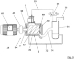
- the Figure 5 illustrates a preferred embodiment of a compressor 64, in particular a rotary compressor, with such a gas inlet valve 1.
- the compressor 64 has a drive motor 65, which is connected by means of a coupling device 66 to compressor screws 67 of the Compressor block 5 is operatively connected.
- the coupling device 66 is designed as a gear or as a force converter.
- the compressor block 5 has two compressor screws 67, which are rotatably mounted in the compressor block 5 by means of bearing devices 68, 69.
- the compressor block 5 preferably has a housing 70 which accommodates the compressor screws 67 and has two housing covers 71, 72 arranged at the ends.
- An oil injection device 73 fluidically connects the oil separator tank to the compressor block 5.
- the compressor screws 67 are lubricated by means of the oil injection device 73.
- the compressor block 5 is fluidically connected to the oil separator tank by means of a gas supply line 74.
- a mixture of compressed gas and oil is preferably supplied to the oil separator tank from the compressor block 5 by means of the gas supply line 74.
- the oil separator tank is also fluidically connected to the second cylinder chamber 52 of the gas inlet valve 1 by means of the working pressure supply line 53.
- the second cylinder chamber 52 can be switchably pressurized with the gas pressure, in particular the working pressure, prevailing in the oil separator tank via the valve 61.
- the oil separator tank 54 can be connected to a compressed air network by means of a connecting flange 75.
- the operation of the compressor 64 is explained below.
- the valve 61 which is preferably designed as a solenoid valve, is open when de-energized.
- the second cylinder chamber 52 is vented and connected to the environment 1 via the working pressure supply line 53.
- the gas inlet valve 1 is closed due to the spring force F F of the spring device 36.
- a start command is first given by a control of the compressor 64.
- the valve 61 initially remains without power.
- the drive motor 65 preferably starts in a star connection.
- the drive motor 65 drives the compressor screws 67 via the coupling device 66. Since the valve body 57 is pressed against its valve seat 56 due to the spring force F F of the spring device 36, a negative pressure is generated in the gas outlet section 4 of the gas inlet valve 1. This negative pressure also acts in the first cylinder chamber 49 due to the fluidic operative connection of the first cylinder chamber 49 with the gas outlet section 4, which is realized by means of the fluid line 39 provided in the piston rod 38.
- the valve body 57 Due to the force ratios between the effective surface of the first piston section 43, on which the force F O acts, the effective surface of the valve body 57, on which the force F U acts, and the spring device 36, which generates the force F F , the valve body 57 remains in contact with the valve seat 56 and the valve device 6 thus remains closed.
- the bridging device 16 is opened at a predetermined gas pressure. A small amount of gas can thus pass through the bridging device 16 past the closed valve device 6 from the gas inlet section 3 into the gas outlet section 4.
- the gas flowing through the bridging device 16 is compressed and fed to the oil separator tank in a mixture with Oil is supplied. This creates a slight overpressure of approximately 1 bar in the oil separator tank. This drives the oil circuit with the oil injection device 73 to lubricate the compressor screws 67.
- the drive motor 65 is switched from star to delta connection. The predetermined period of time depends on the compressor type.
- the control system issues a load command, the valve 61 is energized and opens the working pressure supply line 53 from the oil separator tank to the second cylinder chamber 52.
- the gas pressure of the oil separator tank is now present in the second cylinder chamber 52 and acts against the spring force F F of the spring device 36.
- the opening of the valve device 6, i.e. the lifting of the valve body 57 from its valve seat 56, takes place, for example, immediately, completely or successively.
- both the negative pressure in the gas outlet section 4 and in the first cylinder chamber 49 are reduced to almost zero.
- the gas inlet valve 1 is completely open and the compressor 64 is running at full load.
- the spring force F F of the spring device 36 is sufficient for the valve device 6 to close.
- the compressor 64 is controlled by a proportional controller in the range of approximately 10 to 100% of its delivery quantity.
- the proportional controller is preferably designed as a so-called "negative controller”. This means that as the inlet pressure at the proportional controller increases, its outlet pressure decreases and vice versa.
- the gas inlet valve 1 can be opened continuously by changing, in particular increasing, inlet pressure. Depending on the compressed air requirement, a constant system outlet pressure is thus established at the connection flange 75 of the compressor 64.
- the gas inlet valve 1 described here has a number of advantages. Because the piston device 42 has the first piston section 43 and the second piston section 44 which differs from the first piston section 43, the effective area of the second piston section 44 being significantly smaller than the effective area of the first piston section 43, the second piston section 44 has the advantages of smaller frictional forces, smaller stick-slip effects and a reduced seal diameter.
- the second cylinder chamber 52 of the gas inlet valve 1 described here is also significantly smaller compared to the prior art. Since this second cylinder chamber 52 has to be relieved/vented during switching operations, a smaller volume is advantageous. A small volume of the second cylinder chamber 52 means that the duration of the venting process can be kept short or smaller line cross-sections can be selected for the same venting duration.
- the control pressure of the oil separator tank supports the closing movement of the valve body, in particular when starting the compressor and when switching from full load to idle.
- the gas inlet valve according to the prior art is in the open position due to the gravity of the valve body.
- the gas inlet valve is open. It can only be closed by applying the control pressure.
- a leak or a defect in one of the control lines or a defect in one of the valves can lead to the gas inlet valve no longer closing according to the prior art and the compressor can therefore no longer switch to idle.
- One possible consequence is a pressure increase above the compressor nominal pressure.
- the gas inlet valve 1 described here is closed without pressure due to the spring force F F of the spring device 36.
- the gas pressure of the oil separator tank 54 supports the opening of the valve device 6, i.e. the actuation of the gas inlet valve 1 when switching the compressor 64 from the idle operating state to the full load operating state.
- control of the gas inlet valve 1 described here is comparatively simple compared to the prior art.
- the gas inlet valve 1 can be controlled via the valve 61, which is preferably designed as a 3/2-way valve.
- the following components are not required for controlling the gas inlet valve 1 described here: relief valve, nozzle and/or check valve.
- a single control line in the form of the working pressure supply line 53 is sufficient for controlling the gas inlet valve 1.
Landscapes
- Engineering & Computer Science (AREA)
- Mechanical Engineering (AREA)
- General Engineering & Computer Science (AREA)
- Physics & Mathematics (AREA)
- Fluid Mechanics (AREA)
- Compressor (AREA)
- Fluid-Driven Valves (AREA)
- Applications Or Details Of Rotary Compressors (AREA)
Claims (15)
- Soupape d'entrée de gaz (1) pour un compresseur (64), en particulier pour un compresseur rotatif, comportant :un boîtier (2) comportant une portion d'entrée de gaz (3) pour aspirer un gaz et une portion de sortie de gaz (4) pouvant être mise en communication fluidique opérationnelle avec la portion d'entrée de gaz (3) afin de conduire le gaz aspiré jusqu'à un bloc de compresseur (5) du compresseur (64), en fonction des besoins ;un dispositif à soupape (6) agencé entre la portion d'entrée de gaz (3) et la portion de sortie de gaz (4), comportant un corps de soupape (57) et un siège de soupape (56), dans laquelle le corps de soupape (57) repose de manière étanche contre le siège de soupape (56) lorsque le dispositif à soupape (6) est dans un état de fonctionnement fermé, et dans laquelle le corps de soupape (57) est soulevé du siège de soupape (56) lorsque le dispositif à soupape (6) est dans un état de fonctionnement ouvert ;un dispositif à piston (42) comportant une première portion de piston (43) et une seconde partie de piston (44) différente de la première portion de piston (43), dans laquelle la première portion de piston (43) est guidée de manière mobile dans une première portion de cylindre (22) du boîtier (2) et la seconde portion de piston (44) est guidée de manière mobile dans une seconde portion de cylindre (27) du boîtier (2), différente de la première portion de cylindre (22), dans laquelle la première portion de cylindre (22) a un diamètre DZ1, la seconde portion de cylindre (27) a un diamètre DZ2, la première portion de piston (43) a un diamètre DK1 adapté au diamètre DZ1 de la première portion de cylindre (22), la seconde portion de piston (44) a un diamètre DK2 correspondant au diamètre DZ2 de la seconde portion de cylindre (27) ; etune tige de piston (38) montée de manière mobile dans le boîtier (2), qui accouple mécaniquement le corps de soupape (57) du dispositif à soupape (2) et le dispositif à piston (22), dans laquelle une conduite de fluide (39) met en communication fluidique opérationnelle une première chambre de cylindre (49) de la première portion de cylindre (42) et la portion de sortie de gaz (4), dans laquelle une pression de commande peut être appliquée à une seconde chambre de cylindre (52) de la seconde portion de cylindre (27) afin de soulever le corps de soupape (57) du siège de soupape (56), caractérisée en ce quele diamètre DK1 de la première portion de piston (43) est plus grand que le diamètre DK2 de la seconde portion de piston (44), etune surface active de la première portion de piston (43) à laquelle une pression peut être appliquée est au moins égale à deux fois une surface active de la seconde portion de piston (44) à laquelle une pression peut être appliquée.
- Soupape d'entrée de gaz selon la revendication 1,
dans laquelle la tige de piston (38) comporte la conduite de fluide (39), dans laquelle la conduite de fluide (39) est en particulier réalisée sous la forme d'un canal de fluide s'étendant dans la tige de piston (38), ou la conduite de fluide (39) est réalisée sous la forme d'un canal de fluide s'étendant dans le boîtier (2), en particulier dans une paroi du boîtier (2). - Soupape d'entrée de gaz selon la revendication 1 ou 2,
dans laquelle la soupape d'entrée de gaz (1) comporte un dispositif à ressort (36) qui précontraint élastiquement le dispositif à piston (42) en direction d'un couvercle de boîtier (24) du boîtier (2). - Soupape d'entrée de gaz selon la revendication 3,
dans laquelle le dispositif à ressort (36) est agencé entre le dispositif à piston (42) et le dôme de soupape (34) du boîtier (2), dans laquelle le dispositif à ressort (36) précontraint élastiquement le corps de soupape (57) contre son siège de soupape (56) au moyen de la tige de piston (38), par l'intermédiaire de l'accouplement mécanique du dispositif à piston (42) et du corps de soupape (57). - Soupape d'entrée de gaz selon au moins l'une des revendications précédentes,
dans laquelle la soupape d'entrée de gaz (1) comporte un dispositif de pontage (16) qui met en communication fluidique opérationnelle la portion d'entrée de gaz (3) et la portion de sortie de gaz (4) en contournant le dispositif à soupape (6) fermé, en fonction des besoins, en particulier lorsque la soupape d'entrée de gaz (1) est dans un état de fonctionnement à vide, dans laquelle le dispositif de pontage (6) est de préférence conçu pour fonctionner selon le principe de fonctionnement d'un clapet anti-retour. - Soupape d'entrée de gaz selon au moins l'une des revendications précédentes,
dans laquelle une surface active de la première portion de piston (43) est plus grande qu'une surface active de la seconde portion de piston (44), la surface active de la première portion de piston (43) étant en particulier plus grande que la surface active de la seconde portion de piston (44) d'un facteur au moins égal à 15. - Soupape d'entrée de gaz selon la revendication 6,
dans laquelle la surface active de la première portion de piston (43) correspond à 0,7 à 1,5 fois, en particulier 1 à 1,1 fois, une surface active du corps de soupape (57). - Soupape d'entrée de gaz selon au moins l'une des revendications précédentes,
dans laquelle une surface active de la première portion de piston (43) et une surface active du corps de soupape (57) sont dimensionnées de telle sorte que le dispositif à soupape (6), lorsque l'air de la seconde chambre de cylindre (52) est purgé, reste dans son état de fonctionnement fermé, quel que soit un état de fonctionnement du compresseur (64), en raison de forces (FO, FU) agissant sur la première portion de piston (43) et le corps de soupape (57) et en raison d'une force élastique (FF) du dispositif à ressort (36) agissant sur le corps de soupape (57 ), et le dispositif à soupape (6) peut être uniquement ouvert en appliquant une pression de commande sur la seconde chambre de cylindre (52). - Soupape d'entrée de gaz selon au moins l'une des revendications précédentes,
dans laquelle le corps de soupape (57) est monté de manière mobile sur la tige de piston (38). - Soupape d'entrée de gaz selon au moins l'une des revendications précédentes,
dans laquelle le dispositif à soupape (6) comporte un ressort (60) qui est agencé entre un élément de limitation (59) de la tige de piston (38) et le corps de soupape (57). - Soupape d'entrée de gaz selon la revendication 10,
dans laquelle le ressort (60) est conçu pour supporter un poids propre du corps de soupape (57). - Compresseur, en particulier compresseur rotatif, comportant une soupape d'entrée de gaz (1) selon l'une des revendications précédentes.
- Procédé pour faire fonctionner un compresseur (64), en particulier un compresseur rotatif, comportant une soupape d'entrée de gaz (1), dans lequel la soupape d'entrée de gaz comporte :un boîtier (2) comportant une portion d'entrée de gaz (3) pour aspirer un gaz et une portion de sortie de gaz (4) pouvant être mise en communication fluidique opérationnelle avec la portion d'entrée de gaz (3) afin de conduire le gaz aspiré jusqu'à un bloc de compresseur (5) du compresseur (64), en fonction des besoins ;un dispositif à soupape (6) agencé entre la portion d'entrée de gaz (3) et la portion de sortie de gaz (4) comportant un corps de soupape (57) et un siège de soupape (56), dans lequel le corps de soupape (57) repose de manière étanche contre le siège de soupape (56) lorsque le dispositif à soupape (6) est dans un état de fonctionnement fermé, et dans lequel le corps de soupape (57) est soulevé du siège de soupape (56) lorsque le dispositif à soupape (6) est dans un état de fonctionnement ouvert ;un dispositif à piston (42) comportant une première portion de piston (43) et une seconde portion de piston (44) différente de la première portion de piston (43), dans lequel la première portion de piston (43) est guidée de manière mobile dans une première portion de cylindre (22) du boîtier (2) et la seconde portion de piston (44) est guidée de manière mobile dans une seconde portion de cylindre (27) du boîtier (2), différente de la première portion de cylindre (22), dans lequel la première portion de cylindre (22) a un diamètre DZ1, la seconde portion de cylindre (27) a un diamètre DZ2, la première portion de piston (43) a un diamètre DK1 adapté au diamètre DZ1 de la première portion de cylindre (22), la seconde portion de piston (44) a un diamètre DK2 correspondant au diamètre DZ2 de la seconde portion de cylindre (27), et le diamètre DK1 de la première portion de piston (43) est supérieur au diamètre DK2 de la seconde portion de piston (44) ;dans lequel une surface active de la première portion de piston (43) à laquelle une pression peut être appliquée est au moins égale à deux fois une surface active de la seconde portion de piston (44) à laquelle une pression peut être appliquée ;une tige de piston (38) montée de manière mobile dans le boîtier (2), qui accouple mécaniquement le corps de soupape (57) du dispositif à soupape (6) et le dispositif à piston (42), dans lequel une conduite de fluide (39) met en communication fluidique opérationnelle une première chambre de cylindre (49) de la première portion de cylindre (42) et la portion de sortie de gaz (4), dans lequel une pression de commande est appliquée à une seconde chambre de cylindre (52) de la seconde portion de cylindre (27) afin de soulever le corps de soupape (57) du siège de soupape (56) ; etun dispositif de pontage (16) qui met en communication fluidique opérationnelle la portion d'entrée de gaz (3) et la portion de sortie de gaz (4) en contournant le dispositif à soupape (6) fermé, en fonction des besoins ;dans lequel le procédé comporte les étapes suivantes consistant à :démarrer un moteur d'entraînement (65) du compresseur (64) et produire une dépression dans la portion de sortie de gaz (4) de la soupape d'entrée de gaz (1), le dispositif à soupape (6) étant fermé ;ouvrir, de manière commandée en pression, le dispositif de pontage (16) au moyen de la dépression régnant dans la portion de sortie de gaz (4) afin de conduire le gaz aspiré via le dispositif de pontage (16) depuis la portion d'entrée de gaz (3) jusqu'à la portion de sortie de gaz (4) ;comprimer le gaz aspiré dans le bloc de compresseur (5) ; isoler une conduite d'alimentation en pression de service (53) entre un espace de pression (54) du compresseur (64) et la seconde chambre de cylindre (52) de la soupape d'entrée de gaz (1) ; etouvrir le dispositif à soupape (6) au moyen de la seconde chambre de cylindre (52) mise sous pression.
- Procédé selon la revendication 13,
dans lequel le dispositif à piston (42) est déplacé à l'encontre d'une force élastique (FF) du dispositif à ressort (36) lors de l'ouverture du dispositif à soupape (6) . - Procédé selon la revendication 13 ou 14,dans lequel une surface active de la première portion de piston (43) et une surface active du corps de soupape (57) sont dimensionnées de telle sorte que le dispositif à soupape (6), lorsque l'air de la seconde chambre de cylindre (52) est purgé, reste dans son état de fonctionnement fermé, quel que soit un état de fonctionnement du compresseur, en raison de forces (FO, FU) agissant sur la première portion de piston (43) et le corps de soupape (57) et en raison d'une force élastique (FF) du dispositif à ressort (36) agissant sur le corps de soupape (57), eten ce que le dispositif à soupape (6) peut être uniquement ouvert en appliquant une pression de commande sur la seconde chambre de cylindre (52).
Applications Claiming Priority (1)
| Application Number | Priority Date | Filing Date | Title |
|---|---|---|---|
| DE102011084811A DE102011084811B3 (de) | 2011-10-19 | 2011-10-19 | Gaseinlassventil für einen Kompressor, Kompressor mit einem derartigen Gaseinlassventil sowie Verfahren zum Betreiben eines Kompressors mit einem derartigen Gaseinlassventil |
Publications (4)
| Publication Number | Publication Date |
|---|---|
| EP2584200A2 EP2584200A2 (fr) | 2013-04-24 |
| EP2584200A3 EP2584200A3 (fr) | 2017-07-12 |
| EP2584200B1 true EP2584200B1 (fr) | 2024-04-17 |
| EP2584200B8 EP2584200B8 (fr) | 2024-06-05 |
Family
ID=47172319
Family Applications (1)
| Application Number | Title | Priority Date | Filing Date |
|---|---|---|---|
| EP12189089.1A Active EP2584200B8 (fr) | 2011-10-19 | 2012-10-18 | Valve d'entrée de gaz pour un compresseur, compresseur équipé d'une telle valve d'entrée de gaz et procédé de fonctionnement d'un compresseur équipé d'une telle valve d'entrée de gaz |
Country Status (6)
| Country | Link |
|---|---|
| US (1) | US9651048B2 (fr) |
| EP (1) | EP2584200B8 (fr) |
| DE (1) | DE102011084811B3 (fr) |
| ES (1) | ES2980670T3 (fr) |
| FI (1) | FI2584200T3 (fr) |
| PL (1) | PL2584200T3 (fr) |
Families Citing this family (19)
| Publication number | Priority date | Publication date | Assignee | Title |
|---|---|---|---|---|
| DE102011084811B3 (de) * | 2011-10-19 | 2012-12-27 | Kaeser Kompressoren Ag | Gaseinlassventil für einen Kompressor, Kompressor mit einem derartigen Gaseinlassventil sowie Verfahren zum Betreiben eines Kompressors mit einem derartigen Gaseinlassventil |
| DE102013010780A1 (de) * | 2013-06-28 | 2014-12-31 | GEA AWP GmbH | Rückschlagventil-Filter-Baugruppe |
| JP6253278B2 (ja) * | 2013-07-03 | 2017-12-27 | 日立ジョンソンコントロールズ空調株式会社 | 冷凍サイクル |
| ITBO20130351A1 (it) * | 2013-07-05 | 2015-01-06 | Gardner Denver S R L | Valvola di avviamento di una macchina operatrice a fluido funzionante in un impianto sottovuoto |
| DE102014010534A1 (de) * | 2014-07-19 | 2016-01-21 | Gea Refrigeration Germany Gmbh | Schraubenverdichter |
| CN107208642B (zh) * | 2015-01-15 | 2019-12-31 | 阿特拉斯·科普柯空气动力股份有限公司 | 入口阀和具有这种入口阀的真空泵 |
| BE1023111B1 (nl) * | 2015-01-15 | 2016-11-23 | Atlas Copco Airpower Naamloze Vennootschap | Inlaatklep en vacuümpomp voorzien van een dergelijke inlaatklep. |
| WO2018234910A1 (fr) * | 2017-06-21 | 2018-12-27 | Atlas Copco Airpower, Naamloze Vennootschap | Soupape d'admission pour l'entrée d'un élément de compresseur et compresseur et élément de compresseur équipé d'une telle soupape d'admission |
| EP3722610B1 (fr) * | 2017-12-08 | 2024-10-09 | Hitachi Industrial Equipment Systems Co., Ltd. | Compresseur à vis pour alimentation en liquide |
| CN108433747A (zh) * | 2018-04-11 | 2018-08-24 | 中山大学中山眼科中心 | 负压式液态标本的采集装置 |
| CN108757449B (zh) * | 2018-07-24 | 2024-06-07 | 凤阳汇通压缩机制造股份有限公司 | 一种曲线旋转活塞泵 |
| US11123505B2 (en) | 2018-12-05 | 2021-09-21 | Aires Medical LLC | Breathing apparatus with breath detection software |
| US11229763B2 (en) * | 2018-12-05 | 2022-01-25 | Aires Medical LLC | Mechanical ventilator with oxygen concentrator |
| US11400250B2 (en) | 2018-12-05 | 2022-08-02 | Aires Medical LLC | Mechanical ventilator with non-invasive option |
| US11135392B2 (en) | 2018-12-05 | 2021-10-05 | Aires Medical LLC | Mechanical ventilator |
| US12589213B2 (en) | 2018-12-05 | 2026-03-31 | Goldman Sephoric Llc | Mechanical ventilator with non-invasive option |
| CN113175431A (zh) * | 2021-04-19 | 2021-07-27 | 南通贝科真空机械有限公司 | 一种气阀可调节的螺杆真空泵 |
| WO2023198315A1 (fr) * | 2022-04-15 | 2023-10-19 | Eaton Intelligent Power Limited | Refroidissement à l'air forcé d'un compresseur d'air à l'aide d'une aspiration de compresseur |
| CN119532166B (zh) * | 2024-12-02 | 2026-04-03 | 九江鸿利达复合材料制造有限公司 | 一种空压机进气装置 |
Family Cites Families (10)
| Publication number | Priority date | Publication date | Assignee | Title |
|---|---|---|---|---|
| GB385801A (en) * | 1931-04-18 | 1933-01-05 | Swiss Locomotive & Machine Works | Improvements in and relating to air or gas compressors |
| JPH0255892A (ja) * | 1988-08-19 | 1990-02-26 | Kobe Steel Ltd | スクリュ式真空ポンプ |
| AT402542B (de) * | 1992-06-02 | 1997-06-25 | Hoerbiger Ventilwerke Ag | Ansaugregelventil |
| JP3745427B2 (ja) * | 1995-11-14 | 2006-02-15 | Smc株式会社 | 真空圧制御用スロー排気バルブ |
| US6431210B1 (en) * | 2001-03-27 | 2002-08-13 | Ingersoll-Rand Company | Inlet unloader valve |
| BE1014301A3 (nl) * | 2001-07-17 | 2003-08-05 | Atlas Copco Airpower Nv | Volumetrische compressor. |
| BE1015079A4 (nl) * | 2002-08-22 | 2004-09-07 | Atlas Copco Airpower Nv | Compressor met drukontlasting. |
| DE102008031024A1 (de) * | 2008-06-30 | 2009-12-31 | Wabco Gmbh | Ventil |
| US8469333B2 (en) * | 2010-03-13 | 2013-06-25 | Synapse Engineering, Inc. | Counter-biased valve and actuator assembly |
| DE102011084811B3 (de) * | 2011-10-19 | 2012-12-27 | Kaeser Kompressoren Ag | Gaseinlassventil für einen Kompressor, Kompressor mit einem derartigen Gaseinlassventil sowie Verfahren zum Betreiben eines Kompressors mit einem derartigen Gaseinlassventil |
-
2011
- 2011-10-19 DE DE102011084811A patent/DE102011084811B3/de active Active
-
2012
- 2012-10-18 EP EP12189089.1A patent/EP2584200B8/fr active Active
- 2012-10-18 ES ES12189089T patent/ES2980670T3/es active Active
- 2012-10-18 US US13/655,259 patent/US9651048B2/en active Active
- 2012-10-18 PL PL12189089.1T patent/PL2584200T3/pl unknown
- 2012-10-18 FI FIEP12189089.1T patent/FI2584200T3/fi active
Also Published As
| Publication number | Publication date |
|---|---|
| PL2584200T3 (pl) | 2024-08-26 |
| EP2584200B8 (fr) | 2024-06-05 |
| FI2584200T3 (fi) | 2024-07-22 |
| EP2584200A2 (fr) | 2013-04-24 |
| ES2980670T3 (es) | 2024-10-02 |
| DE102011084811B3 (de) | 2012-12-27 |
| EP2584200A3 (fr) | 2017-07-12 |
| US9651048B2 (en) | 2017-05-16 |
| US20130136638A1 (en) | 2013-05-30 |
Similar Documents
| Publication | Publication Date | Title |
|---|---|---|
| EP2584200B1 (fr) | Valve d'entrée de gaz pour un compresseur, compresseur équipé d'une telle valve d'entrée de gaz et procédé de fonctionnement d'un compresseur équipé d'une telle valve d'entrée de gaz | |
| EP1941138B1 (fr) | Soupape de surpression destinee a des moteurs a combustion interne comportant un turbocompresseur | |
| DE3877980T2 (de) | Mehrstufen-vakuumpumpe. | |
| EP2739556B1 (fr) | Dispositif de commande pour un entraînement hydraulique | |
| EP2739886B1 (fr) | Soupape | |
| AT402542B (de) | Ansaugregelventil | |
| EP3063412A1 (fr) | Pompe à réfrigérant réglable | |
| DE2308265A1 (de) | Rotations- bzw. drehkolbenverdichter anlage mit oelkreislauf und ventilanordnungen | |
| EP1283971A1 (fr) | Pompe regulee | |
| DE3803187C2 (de) | Flügelzellenverdichter mit variabler Förderleistung | |
| EP0839283A1 (fr) | Pompe a vide a palettes rendue etanche a l'huile, avec alimentation en huile | |
| EP0084085B1 (fr) | Pompe à vide avec une soupape dans la tubulure d'aspiration et son procédé de mise en activité | |
| DE19621414C2 (de) | Schraubenverdichter mit eingebautem Bypaßkanal | |
| DE4006156C2 (de) | Kolbenverdichter, insbesondere für die Drucklufterzeugung in Kraftfahrzeugen | |
| DE102006016318B4 (de) | Schraubenverdichter mit Entlastungsventil | |
| DE102009060188B4 (de) | Verstellventil für die Verstellung des Fördervolumens einer Verdrängerpumpe mit Kaltstartfunktion | |
| AT502337B1 (de) | Trockenlaufender schraubenverdichter mit pneumatisch gesteuertem entlüftungsventil | |
| EP1998045A1 (fr) | Machine volumétrique avec soupapes coaxiales | |
| DE102013102661B4 (de) | Positionsausgeglichene Ventilspindel | |
| WO2015139821A1 (fr) | Compresseur de gaz et procédé pour faire fonctionner ce compresseur de gaz | |
| EP1725771A1 (fr) | Compresseur, en particulier compresseur a pistons axiaux pour une installation de climatisation de vehicule | |
| DD241454A1 (de) | Druckentlastungs-rueckschlagventil, insbesondere fuer kaeltemittel-hubkolbenverdichter | |
| EP4359672A1 (fr) | Compresseur à vis | |
| AT504911B1 (de) | Drehschieberpumpe | |
| EP1659308B1 (fr) | Dispositif d'embrayage pour l'accouplement d'un dispositif auxiliiaire |
Legal Events
| Date | Code | Title | Description |
|---|---|---|---|
| PUAI | Public reference made under article 153(3) epc to a published international application that has entered the european phase |
Free format text: ORIGINAL CODE: 0009012 |
|
| AK | Designated contracting states |
Kind code of ref document: A2 Designated state(s): AL AT BE BG CH CY CZ DE DK EE ES FI FR GB GR HR HU IE IS IT LI LT LU LV MC MK MT NL NO PL PT RO RS SE SI SK SM TR |
|
| AX | Request for extension of the european patent |
Extension state: BA ME |
|
| RAP1 | Party data changed (applicant data changed or rights of an application transferred) |
Owner name: KAESER KOMPRESSOREN SE |
|
| PUAL | Search report despatched |
Free format text: ORIGINAL CODE: 0009013 |
|
| AK | Designated contracting states |
Kind code of ref document: A3 Designated state(s): AL AT BE BG CH CY CZ DE DK EE ES FI FR GB GR HR HU IE IS IT LI LT LU LV MC MK MT NL NO PL PT RO RS SE SI SK SM TR |
|
| AX | Request for extension of the european patent |
Extension state: BA ME |
|
| RIC1 | Information provided on ipc code assigned before grant |
Ipc: F04C 28/06 20060101ALI20170607BHEP Ipc: F04C 28/24 20060101ALI20170607BHEP Ipc: F04C 28/26 20060101AFI20170607BHEP Ipc: F04C 18/16 20060101ALI20170607BHEP Ipc: F04C 29/12 20060101ALI20170607BHEP |
|
| STAA | Information on the status of an ep patent application or granted ep patent |
Free format text: STATUS: REQUEST FOR EXAMINATION WAS MADE |
|
| 17P | Request for examination filed |
Effective date: 20180112 |
|
| RBV | Designated contracting states (corrected) |
Designated state(s): AL AT BE BG CH CY CZ DE DK EE ES FI FR GB GR HR HU IE IS IT LI LT LU LV MC MK MT NL NO PL PT RO RS SE SI SK SM TR |
|
| STAA | Information on the status of an ep patent application or granted ep patent |
Free format text: STATUS: EXAMINATION IS IN PROGRESS |
|
| 17Q | First examination report despatched |
Effective date: 20200203 |
|
| P01 | Opt-out of the competence of the unified patent court (upc) registered |
Effective date: 20230412 |
|
| GRAP | Despatch of communication of intention to grant a patent |
Free format text: ORIGINAL CODE: EPIDOSNIGR1 |
|
| STAA | Information on the status of an ep patent application or granted ep patent |
Free format text: STATUS: GRANT OF PATENT IS INTENDED |
|
| INTG | Intention to grant announced |
Effective date: 20230719 |
|
| GRAJ | Information related to disapproval of communication of intention to grant by the applicant or resumption of examination proceedings by the epo deleted |
Free format text: ORIGINAL CODE: EPIDOSDIGR1 |
|
| STAA | Information on the status of an ep patent application or granted ep patent |
Free format text: STATUS: EXAMINATION IS IN PROGRESS |
|
| INTC | Intention to grant announced (deleted) | ||
| GRAP | Despatch of communication of intention to grant a patent |
Free format text: ORIGINAL CODE: EPIDOSNIGR1 |
|
| STAA | Information on the status of an ep patent application or granted ep patent |
Free format text: STATUS: GRANT OF PATENT IS INTENDED |
|
| INTG | Intention to grant announced |
Effective date: 20231115 |
|
| GRAS | Grant fee paid |
Free format text: ORIGINAL CODE: EPIDOSNIGR3 |
|
| GRAA | (expected) grant |
Free format text: ORIGINAL CODE: 0009210 |
|
| STAA | Information on the status of an ep patent application or granted ep patent |
Free format text: STATUS: THE PATENT HAS BEEN GRANTED |
|
| REG | Reference to a national code |
Ref country code: DE Ref legal event code: R108 Ref document number: 502012017254 Country of ref document: DE |
|
| AK | Designated contracting states |
Kind code of ref document: B1 Designated state(s): AL AT BE BG CH CY CZ DE DK EE ES FI FR GB GR HR HU IE IS IT LI LT LU LV MC MK MT NL NO PL PT RO RS SE SI SK SM TR |
|
| REG | Reference to a national code |
Ref country code: GB Ref legal event code: FG4D Free format text: NOT ENGLISH |
|
| REG | Reference to a national code |
Ref country code: CH Ref legal event code: EP |
|
| REG | Reference to a national code |
Ref country code: IE Ref legal event code: FG4D Free format text: LANGUAGE OF EP DOCUMENT: GERMAN Ref country code: DE Ref legal event code: R096 Ref document number: 502012017254 Country of ref document: DE |
|
| REG | Reference to a national code |
Ref country code: CH Ref legal event code: PK Free format text: BERICHTIGUNG B8 |
|
| RBV | Designated contracting states (corrected) |
Designated state(s): AL AT BE BG CH CY CZ DK EE ES FI FR GB GR HR HU IE IS IT LI LT LU LV MC MK MT NL NO PL PT RO RS SE SI SK SM TR |
|
| REG | Reference to a national code |
Ref country code: DE Ref legal event code: R107 Ref document number: 502012017254 Country of ref document: DE |
|
| REG | Reference to a national code |
Ref country code: FI Ref legal event code: FGE |
|
| REG | Reference to a national code |
Ref country code: LT Ref legal event code: MG9D |
|
| REG | Reference to a national code |
Ref country code: NL Ref legal event code: MP Effective date: 20240417 |
|
| PG25 | Lapsed in a contracting state [announced via postgrant information from national office to epo] |
Ref country code: NL Free format text: LAPSE BECAUSE OF FAILURE TO SUBMIT A TRANSLATION OF THE DESCRIPTION OR TO PAY THE FEE WITHIN THE PRESCRIBED TIME-LIMIT Effective date: 20240417 |
|
| PG25 | Lapsed in a contracting state [announced via postgrant information from national office to epo] |
Ref country code: NL Free format text: LAPSE BECAUSE OF FAILURE TO SUBMIT A TRANSLATION OF THE DESCRIPTION OR TO PAY THE FEE WITHIN THE PRESCRIBED TIME-LIMIT Effective date: 20240417 |
|
| REG | Reference to a national code |
Ref country code: ES Ref legal event code: FG2A Ref document number: 2980670 Country of ref document: ES Kind code of ref document: T3 Effective date: 20241002 |
|
| PG25 | Lapsed in a contracting state [announced via postgrant information from national office to epo] |
Ref country code: IS Free format text: LAPSE BECAUSE OF FAILURE TO SUBMIT A TRANSLATION OF THE DESCRIPTION OR TO PAY THE FEE WITHIN THE PRESCRIBED TIME-LIMIT Effective date: 20240817 |
|
| PG25 | Lapsed in a contracting state [announced via postgrant information from national office to epo] |
Ref country code: BG Free format text: LAPSE BECAUSE OF FAILURE TO SUBMIT A TRANSLATION OF THE DESCRIPTION OR TO PAY THE FEE WITHIN THE PRESCRIBED TIME-LIMIT Effective date: 20240417 |
|
| PG25 | Lapsed in a contracting state [announced via postgrant information from national office to epo] |
Ref country code: HR Free format text: LAPSE BECAUSE OF FAILURE TO SUBMIT A TRANSLATION OF THE DESCRIPTION OR TO PAY THE FEE WITHIN THE PRESCRIBED TIME-LIMIT Effective date: 20240417 |
|
| PG25 | Lapsed in a contracting state [announced via postgrant information from national office to epo] |
Ref country code: GR Free format text: LAPSE BECAUSE OF FAILURE TO SUBMIT A TRANSLATION OF THE DESCRIPTION OR TO PAY THE FEE WITHIN THE PRESCRIBED TIME-LIMIT Effective date: 20240718 |
|
| PG25 | Lapsed in a contracting state [announced via postgrant information from national office to epo] |
Ref country code: PT Free format text: LAPSE BECAUSE OF FAILURE TO SUBMIT A TRANSLATION OF THE DESCRIPTION OR TO PAY THE FEE WITHIN THE PRESCRIBED TIME-LIMIT Effective date: 20240819 |
|
| PG25 | Lapsed in a contracting state [announced via postgrant information from national office to epo] |
Ref country code: LV Free format text: LAPSE BECAUSE OF FAILURE TO SUBMIT A TRANSLATION OF THE DESCRIPTION OR TO PAY THE FEE WITHIN THE PRESCRIBED TIME-LIMIT Effective date: 20240417 |
|
| PG25 | Lapsed in a contracting state [announced via postgrant information from national office to epo] |
Ref country code: PT Free format text: LAPSE BECAUSE OF FAILURE TO SUBMIT A TRANSLATION OF THE DESCRIPTION OR TO PAY THE FEE WITHIN THE PRESCRIBED TIME-LIMIT Effective date: 20240819 Ref country code: NO Free format text: LAPSE BECAUSE OF FAILURE TO SUBMIT A TRANSLATION OF THE DESCRIPTION OR TO PAY THE FEE WITHIN THE PRESCRIBED TIME-LIMIT Effective date: 20240717 Ref country code: LV Free format text: LAPSE BECAUSE OF FAILURE TO SUBMIT A TRANSLATION OF THE DESCRIPTION OR TO PAY THE FEE WITHIN THE PRESCRIBED TIME-LIMIT Effective date: 20240417 Ref country code: IS Free format text: LAPSE BECAUSE OF FAILURE TO SUBMIT A TRANSLATION OF THE DESCRIPTION OR TO PAY THE FEE WITHIN THE PRESCRIBED TIME-LIMIT Effective date: 20240817 Ref country code: HR Free format text: LAPSE BECAUSE OF FAILURE TO SUBMIT A TRANSLATION OF THE DESCRIPTION OR TO PAY THE FEE WITHIN THE PRESCRIBED TIME-LIMIT Effective date: 20240417 Ref country code: GR Free format text: LAPSE BECAUSE OF FAILURE TO SUBMIT A TRANSLATION OF THE DESCRIPTION OR TO PAY THE FEE WITHIN THE PRESCRIBED TIME-LIMIT Effective date: 20240718 Ref country code: BG Free format text: LAPSE BECAUSE OF FAILURE TO SUBMIT A TRANSLATION OF THE DESCRIPTION OR TO PAY THE FEE WITHIN THE PRESCRIBED TIME-LIMIT Effective date: 20240417 Ref country code: RS Free format text: LAPSE BECAUSE OF FAILURE TO SUBMIT A TRANSLATION OF THE DESCRIPTION OR TO PAY THE FEE WITHIN THE PRESCRIBED TIME-LIMIT Effective date: 20240717 |
|
| PG25 | Lapsed in a contracting state [announced via postgrant information from national office to epo] |
Ref country code: DK Free format text: LAPSE BECAUSE OF FAILURE TO SUBMIT A TRANSLATION OF THE DESCRIPTION OR TO PAY THE FEE WITHIN THE PRESCRIBED TIME-LIMIT Effective date: 20240417 |
|
| PGFP | Annual fee paid to national office [announced via postgrant information from national office to epo] |
Ref country code: PL Payment date: 20241015 Year of fee payment: 13 |
|
| PG25 | Lapsed in a contracting state [announced via postgrant information from national office to epo] |
Ref country code: EE Free format text: LAPSE BECAUSE OF FAILURE TO SUBMIT A TRANSLATION OF THE DESCRIPTION OR TO PAY THE FEE WITHIN THE PRESCRIBED TIME-LIMIT Effective date: 20240417 |
|
| PGFP | Annual fee paid to national office [announced via postgrant information from national office to epo] |
Ref country code: FR Payment date: 20241021 Year of fee payment: 13 |
|
| PG25 | Lapsed in a contracting state [announced via postgrant information from national office to epo] |
Ref country code: CZ Free format text: LAPSE BECAUSE OF FAILURE TO SUBMIT A TRANSLATION OF THE DESCRIPTION OR TO PAY THE FEE WITHIN THE PRESCRIBED TIME-LIMIT Effective date: 20240417 |
|
| PG25 | Lapsed in a contracting state [announced via postgrant information from national office to epo] |
Ref country code: RO Free format text: LAPSE BECAUSE OF FAILURE TO SUBMIT A TRANSLATION OF THE DESCRIPTION OR TO PAY THE FEE WITHIN THE PRESCRIBED TIME-LIMIT Effective date: 20240417 Ref country code: SK Free format text: LAPSE BECAUSE OF FAILURE TO SUBMIT A TRANSLATION OF THE DESCRIPTION OR TO PAY THE FEE WITHIN THE PRESCRIBED TIME-LIMIT Effective date: 20240417 |
|
| PG25 | Lapsed in a contracting state [announced via postgrant information from national office to epo] |
Ref country code: SM Free format text: LAPSE BECAUSE OF FAILURE TO SUBMIT A TRANSLATION OF THE DESCRIPTION OR TO PAY THE FEE WITHIN THE PRESCRIBED TIME-LIMIT Effective date: 20240417 |
|
| PGFP | Annual fee paid to national office [announced via postgrant information from national office to epo] |
Ref country code: ES Payment date: 20241127 Year of fee payment: 13 |
|
| PG25 | Lapsed in a contracting state [announced via postgrant information from national office to epo] |
Ref country code: SM Free format text: LAPSE BECAUSE OF FAILURE TO SUBMIT A TRANSLATION OF THE DESCRIPTION OR TO PAY THE FEE WITHIN THE PRESCRIBED TIME-LIMIT Effective date: 20240417 Ref country code: SK Free format text: LAPSE BECAUSE OF FAILURE TO SUBMIT A TRANSLATION OF THE DESCRIPTION OR TO PAY THE FEE WITHIN THE PRESCRIBED TIME-LIMIT Effective date: 20240417 Ref country code: RO Free format text: LAPSE BECAUSE OF FAILURE TO SUBMIT A TRANSLATION OF THE DESCRIPTION OR TO PAY THE FEE WITHIN THE PRESCRIBED TIME-LIMIT Effective date: 20240417 Ref country code: EE Free format text: LAPSE BECAUSE OF FAILURE TO SUBMIT A TRANSLATION OF THE DESCRIPTION OR TO PAY THE FEE WITHIN THE PRESCRIBED TIME-LIMIT Effective date: 20240417 Ref country code: DK Free format text: LAPSE BECAUSE OF FAILURE TO SUBMIT A TRANSLATION OF THE DESCRIPTION OR TO PAY THE FEE WITHIN THE PRESCRIBED TIME-LIMIT Effective date: 20240417 Ref country code: CZ Free format text: LAPSE BECAUSE OF FAILURE TO SUBMIT A TRANSLATION OF THE DESCRIPTION OR TO PAY THE FEE WITHIN THE PRESCRIBED TIME-LIMIT Effective date: 20240417 |
|
| PLBE | No opposition filed within time limit |
Free format text: ORIGINAL CODE: 0009261 |
|
| STAA | Information on the status of an ep patent application or granted ep patent |
Free format text: STATUS: NO OPPOSITION FILED WITHIN TIME LIMIT |
|
| 26N | No opposition filed |
Effective date: 20250120 |
|
| PG25 | Lapsed in a contracting state [announced via postgrant information from national office to epo] |
Ref country code: SI Free format text: LAPSE BECAUSE OF FAILURE TO SUBMIT A TRANSLATION OF THE DESCRIPTION OR TO PAY THE FEE WITHIN THE PRESCRIBED TIME-LIMIT Effective date: 20240417 |
|
| REG | Reference to a national code |
Ref country code: CH Ref legal event code: PL |
|
| GBPC | Gb: european patent ceased through non-payment of renewal fee |
Effective date: 20241018 |
|
| PG25 | Lapsed in a contracting state [announced via postgrant information from national office to epo] |
Ref country code: MC Free format text: LAPSE BECAUSE OF FAILURE TO SUBMIT A TRANSLATION OF THE DESCRIPTION OR TO PAY THE FEE WITHIN THE PRESCRIBED TIME-LIMIT Effective date: 20240417 |
|
| PG25 | Lapsed in a contracting state [announced via postgrant information from national office to epo] |
Ref country code: GB Free format text: LAPSE BECAUSE OF NON-PAYMENT OF DUE FEES Effective date: 20241018 |
|
| PG25 | Lapsed in a contracting state [announced via postgrant information from national office to epo] |
Ref country code: LU Free format text: LAPSE BECAUSE OF NON-PAYMENT OF DUE FEES Effective date: 20241018 |
|
| PG25 | Lapsed in a contracting state [announced via postgrant information from national office to epo] |
Ref country code: CH Free format text: LAPSE BECAUSE OF NON-PAYMENT OF DUE FEES Effective date: 20241031 |
|
| PG25 | Lapsed in a contracting state [announced via postgrant information from national office to epo] |
Ref country code: SE Free format text: LAPSE BECAUSE OF FAILURE TO SUBMIT A TRANSLATION OF THE DESCRIPTION OR TO PAY THE FEE WITHIN THE PRESCRIBED TIME-LIMIT Effective date: 20240417 |
|
| PG25 | Lapsed in a contracting state [announced via postgrant information from national office to epo] |
Ref country code: IE Free format text: LAPSE BECAUSE OF NON-PAYMENT OF DUE FEES Effective date: 20241018 |
|
| REG | Reference to a national code |
Ref country code: AT Ref legal event code: MM01 Ref document number: 1677490 Country of ref document: AT Kind code of ref document: T Effective date: 20241018 |
|
| PG25 | Lapsed in a contracting state [announced via postgrant information from national office to epo] |
Ref country code: AT Free format text: LAPSE BECAUSE OF NON-PAYMENT OF DUE FEES Effective date: 20241018 |
|
| PGFP | Annual fee paid to national office [announced via postgrant information from national office to epo] |
Ref country code: FI Payment date: 20251028 Year of fee payment: 14 Ref country code: IT Payment date: 20251024 Year of fee payment: 14 |
|
| PGFP | Annual fee paid to national office [announced via postgrant information from national office to epo] |
Ref country code: TR Payment date: 20251015 Year of fee payment: 14 Ref country code: BE Payment date: 20251021 Year of fee payment: 14 |
|
| PG25 | Lapsed in a contracting state [announced via postgrant information from national office to epo] |
Ref country code: CY Free format text: LAPSE BECAUSE OF FAILURE TO SUBMIT A TRANSLATION OF THE DESCRIPTION OR TO PAY THE FEE WITHIN THE PRESCRIBED TIME-LIMIT; INVALID AB INITIO Effective date: 20121018 |
|
| PG25 | Lapsed in a contracting state [announced via postgrant information from national office to epo] |
Ref country code: HU Free format text: LAPSE BECAUSE OF FAILURE TO SUBMIT A TRANSLATION OF THE DESCRIPTION OR TO PAY THE FEE WITHIN THE PRESCRIBED TIME-LIMIT; INVALID AB INITIO Effective date: 20121018 |