EP2584209B1 - Linearschienenführungsanordnung - Google Patents
Linearschienenführungsanordnung Download PDFInfo
- Publication number
- EP2584209B1 EP2584209B1 EP12188755.8A EP12188755A EP2584209B1 EP 2584209 B1 EP2584209 B1 EP 2584209B1 EP 12188755 A EP12188755 A EP 12188755A EP 2584209 B1 EP2584209 B1 EP 2584209B1
- Authority
- EP
- European Patent Office
- Prior art keywords
- linear guideway
- legs
- rollers
- translation axis
- roller
- Prior art date
- Legal status (The legal status is an assumption and is not a legal conclusion. Google has not performed a legal analysis and makes no representation as to the accuracy of the status listed.)
- Active
Links
Images



Classifications
-
- F—MECHANICAL ENGINEERING; LIGHTING; HEATING; WEAPONS; BLASTING
- F16—ENGINEERING ELEMENTS AND UNITS; GENERAL MEASURES FOR PRODUCING AND MAINTAINING EFFECTIVE FUNCTIONING OF MACHINES OR INSTALLATIONS; THERMAL INSULATION IN GENERAL
- F16C—SHAFTS; FLEXIBLE SHAFTS; ELEMENTS OR CRANKSHAFT MECHANISMS; ROTARY BODIES OTHER THAN GEARING ELEMENTS; BEARINGS
- F16C29/00—Bearings for parts moving only linearly
- F16C29/12—Arrangements for adjusting play
-
- F—MECHANICAL ENGINEERING; LIGHTING; HEATING; WEAPONS; BLASTING
- F16—ENGINEERING ELEMENTS AND UNITS; GENERAL MEASURES FOR PRODUCING AND MAINTAINING EFFECTIVE FUNCTIONING OF MACHINES OR INSTALLATIONS; THERMAL INSULATION IN GENERAL
- F16C—SHAFTS; FLEXIBLE SHAFTS; ELEMENTS OR CRANKSHAFT MECHANISMS; ROTARY BODIES OTHER THAN GEARING ELEMENTS; BEARINGS
- F16C29/00—Bearings for parts moving only linearly
- F16C29/04—Ball or roller bearings
- F16C29/045—Ball or roller bearings having rolling elements journaled in one of the moving parts
Definitions
- the present invention relates to linear guide way arrangement for use e.g. in a linear module powered by a belt, a pair of cables or a drive screw.
- Prior art document US 3,998,497 discloses a linear guideway arrangement for guiding a carriage along a linear path defined by first and second horizontal parallel guide rods.
- First and second roller assemblies are fixed to the carriage and rollingly connect the carriage to the first guide rod.
- a third roller assembly fixed to the other side of the carriage rollingly connects the carriage to the second guide rod.
- the third roller assembly comprises a shaft fixed to the carriage and a roller carried by the shaft, which rollingly rides on the top of the second guide rod.
- the first and second roller assemblies each comprise a shaft fixed to the carriage carrying first and second rollers spaced from each other along the shaft. The first and second rollers straddle the top of the first guide rod and rollingly ride on the upper surface thereof.
- the apparatus further comprises a shaft fixed to the carriage and which carries a roller, the top of which rollingly engages with the lower surface of the first guide rod.
- the carriage In order to avoid undesired play between the rollers and guide rods, the carriage has to be mounted on the guide rods with some interference, which results in excessive and uncontrolled friction and wear between the rollers and the guide rods.
- US 6,648,508 discloses a linear guide comprises a travelling carriage having track rollers for support and for rolling along a guide rail, said track rollers, each of which rolls on the guide rail, being mounted in pairs for rotation on a first support that is arranged on a first carriage plate of the travelling carriage.
- the travelling carriage comprises a further carriage plate with a second support arranged thereon, and track rollers rotatably mounted on said second support for rolling on a further guide rail, the two guide rails being parallel to each other and fixed on two longitudinal sides of a central rail support.
- US 2,992,620 discloses a linear guideway arrangement comprising: two lateral tracks parallel to a translation axis of the linear guideway arrangement and spaced apart from one another in a first transverse direction perpendicular to the translation axis; and a carriage comprising a central part and at least two legs spaced apart from one another in the first transverse direction, each of the two legs corresponding to one of the lateral tracks, each of the two legs comprising at least one set of first rollers comprising at least one first roller rotating about a first rotation axis fixed relative to the carriage and perpendicular to the translation axis, wherein each of the two legs is provided with at least one rolling shoe comprising at least one set of second rollers comprising at least one second roller rotating about a second rotation axis fixed relative to the rolling shoe and perpendicular to the translation axis, the rolling shoe of each of the two legs being moveable with respect to the carriage in a protruding direction perpendicular to the translation axis between a retracted and a pro
- US 5,642,941 discloses a linear guidance device comprising: a rail defining a path of movement of a movable assembly and rollers secured to said movable assembly; the rollers being mounted in an elastically deformable block so as to apply the rollers to the rail while exerting a predetermined and substantially constant contact pressure on the guidance rail; the elastically deformable block comprising at least two rigid portions interconnected by means forming an elastic hinge, the means forming an elastic hinge comprising at least one wall of small thickness constituting a region of deformation and permitting relative pivoting between said two rigid portions; and means for adjustment of the contact pressure of the rollers on the guidance rail; said adjustment means comprising an elastic means applying the force of a spring to said elastically deformable block.
- the invention aims at solving the above-described problems.
- a linear guideway arrangement comprising: two lateral tracks parallel to a translation axis of the linear guideway arrangement and spaced apart from one another in a first transverse direction perpendicular to the translation axis; and a carriage comprising a central part and at least two legs spaced apart from one another in the first transverse direction, each of the two legs corresponding to one of the lateral tracks, each of the two legs comprising at least one set of first rollers comprising at least one first roller rotating about a first rotation axis fixed relative to the carriage and perpendicular to the translation axis, wherein each of the two legs is provided with at least one rolling shoe comprising at least one set of second rollers comprising at least one second roller rotating about a second rotation axis fixed relative to the rolling shoe and perpendicular to the translation axis, the rolling shoe of each of the two legs being moveable with respect to the carriage in a protruding direction perpendicular to the translation axis
- Each one of two lateral tracks comprises a first guide rod and a second guide rod parallel to the translation axis of the linear guideway arrangement and spaced apart from the first and second guide rods of the other one of the two lateral tracks in the first transverse direction perpendicular to the translation axis, the at least one first roller rolls on the first of guide rod of the corresponding lateral track.
- the at least one second roller rolls on the second rod of the corresponding lateral track.
- the protruding direction is a direction towards the second guide rod of the corresponding lateral track.
- the rolling shoe of each of the two legs is provided with biasing means for biasing the rolling shoe towards the second guide rod of the corresponding track in the protruding direction.
- each guide leg forms a preassembled subunit with its guide shoe retained in the cavity by the axial clamping releasable fastening means and the loaded biasing means.
- the guide shoe is pushed in its retracted position against the biasing force of the biasing means and the releasable fastening means are tightened to keep this position.
- the carriage is easy to insert into the frame. Once the legs are in place into the respective lateral tracks, the releasable fastening means are loosened.
- the biasing means automatically push the roller shoes towards the protruding position in the protruding direction, until the second rollers engage with the second rods at the appropriate contact pressure defined by the biasing means.
- the releasable fastening means are then tightened once again, to secure the position of each rolling shoe relative to the associated leg. At the end of this step, the assembly of the guideway arrangement is complete.
- the releasable fastening means include screws.
- the biasing means include springs.
- the first rotation axis is preferably parallel to the second rotation axis.
- Each of the two pairs of guide rods defines a corresponding reference plane, each reference plane containing the guide rods of the corresponding pair of guide rods.
- This reference plane is preferably perpendicular to the rotation axes of the leg rollers and of the shoe roller rolling on the guide rods of the corresponding pair of guide rods.
- the reference planes of the two pairs of guide rods are an angle relative to one another.
- the reference planes of the two pairs of guide rods can be perpendicular to one another.
- the first guide rods of the two pairs of guide rods are closer to one another than the second guide rods of the two pairs of guide rods.
- the two pairs of guide rods define a plane of symmetry parallel to the translation axis, the first rods of the two pairs of rods being on each side of and at equal distance from the plane of symmetry, the second rods of the two pairs of rods being on each side of and at equal distance from the plane of symmetry.
- the plane of symmetry is a vertical plane and the first rods of the two pairs of guide rods are above the second guide rods of the two pairs of guide rods.
- each set of first rollers comprises at least two first rollers rotating about two first rotation axes fixed relative to the carriage, perpendicular to the translation axis and spaced apart from one another along the translation axis.
- each set of second rollers comprises two second rollers rotating about two second rotation axes fixed relative to the rolling shoe, perpendicular to the translation axis and spaced apart from one another along the translation axis.
- a linear guideway arrangement 10 comprises a frame 12 made of an extruded aluminium profile.
- the frame 12 is provided with a central track 14 for receiving e.g. a drive screw or a drive belt and two lateral tracks 16 on each side of the central track 14.
- Each lateral track 16 is provided with a pair of guide rods 18, 20.
- the guide rods 18, 20 are parallel to a translation axis 22 of the linear guideway arrangement.
- Each pair of guide rods includes a first, upper guide rod 18 and a second, lower guide rod 20.
- a plane of symmetry 24 can be defined, which is at mid distance between the two pairs of guide rods 18, 20.
- the first guide rods 18 of the two tracks 16 are spaced apart from one another on each side of and at equal distance from the plane of symmetry.
- the second guide rods 20 are spaced apart from one another on each side of and at equal distance from the plane of symmetry.
- a reference plane 26 can be defined, which is parallel to the translation axis 22 and contains a centre line of the respective first and second guide rods 18, 20.
- the two planes 26 are at an angle relative to one another, preferably between 60° and 120°, e.g. a right angle.
- a carriage 28 is mounted on the guideway frame 12 for moving fore and aft parallel to the translation axis 22.
- the carriage 28 includes a central plate 30 and two legs 32 on each side of the central plate 30.
- the central plate 30 and the two legs 32 form a rigid, i.e. non-deformable structure.
- Each of the two legs 32 is received in a corresponding one of the two tracks 16 as will be explained hereinafter.
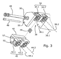
- Each leg 32 comprises a set 34 of first rollers, in the present case a set of two first rollers 34.1, 34.2, rolling on the first guide rod 18 of the corresponding track 16.
- the first rollers of each leg 32 have rotation axes 36.1, 36.2 that are fixed relative to the respective leg 32 , spaced apart from one another and perpendicular to the reference plane 26 of the respective leg 32 .
- Each leg 32 comprises a cavity 38 for receiving a guide shoe 40 provided with a set 42 of second rollers, in the present case of two second rollers 42.1, 42.2, rolling on the second guide rod 20 of the corresponding track 16.
- the second rollers 42.1, 42.2 of each leg 32 have rotation axes 44.1, 44.2 that are fixed relative to the respective leg 32, spaced apart from one another and perpendicular to the reference plane 26 of the respective leg 32.
- each leg has side walls 38.1 for guiding the guide shoe 40 in a protruding direction perpendicular to the first and second guide rods 18, 20 and to the first and second rotation axes 36.1, 36.2, 44.1, 44.2.
- a compression spring 46 is loaded in the cavity 38 for pressing the second rollers 42.1, 42.2 of the guide shoe 40 against the second guide rod 20 and away from the first rollers 34.1, 34.2 and first guide rod 18.
- a set of axial clamping screws 48 is provided for fastening each guide shoe 40 in the cavity 38 of the associated leg 32.
- Each screw 48 is received in through hole 50, 52 having a slightly larger diameter than the associated screw 48, so as to allow a limited freedom of motion of the guide shoe 40 in the cavity 38 as long as the screws 48 are not tightened.
- each of the guide shoes 40 is free to move at least in the protruding direction parallel to the reference plane 26 of the associated leg 32 and perpendicular to the rotation axes 36.1, 36.2, 44.1, 44.2 between a fully retracted position close to the first rollers 34.1, 34.2 and a protruding position away from the first rollers 34.1, 34.2.
- each guide leg 32 forms a preassembled subunit with its guide shoe 40 retained in the cavity 38 by the axial clamping screws and the loaded spring.
- the guide shoe 40 is pushed in its retracted position against the biasing force of the spring 46 and the screws 48 are tightened to keep this position.
- the carriage 28 is easy to insert into the frame. Once the legs 32 are in place into the respective lateral tracks 16, the screws 48 are loosened.
- the springs 46 automatically push the roller shoes 40 towards the protruding position in the protruding direction, until the second rollers 42., 42.2 engage with the second rods 20 at the appropriate contact pressure defined by the spring 46.
- the screws 48 are then tightened once again, to secure the position of each rolling shoe 40 relative to the associated leg 32.
- the assembly of the guideway arrangement 10 is complete.
- the guide rods illustrated in the drawings have a circular cross-section. However, other cross-sectional shapes are possible.
- the shape of the rollers, which in the drawings include a central groove, may be changed accordingly.
- the intersecting reference planes 26 of the two legs are preferred in all situations in which loads or vibrations in several directions perpendicular to the fore and aft direction of the rods is to be expected.
- the two pairs of guide rods 18 , 20 may be coplanar, i.e. on one and the same reference plane 26 . Such an embodiment will be preferred if no load is expected on the carriage perpendicular to the reference plane 26 .
- the reference planes 26 of the two legs can be parallel to one another, if no lateral load perpendicular to the reference planes is expected.
- Each set 34 , 42 of rollers may have one or more rollers.
- the screws can be replaced with other fastening means, e.g. a rotating key.
- the same principle may be used with three guide rods.
Landscapes
- Engineering & Computer Science (AREA)
- General Engineering & Computer Science (AREA)
- Mechanical Engineering (AREA)
- Bearings For Parts Moving Linearly (AREA)
Claims (11)
- Lineare Schienenführungsanordnung (10), umfassend:- zwei seitliche Gleise (16), die parallel zu einer Translationsachse (22) der linearen Schienenführungsanordnung (10) und voneinander in einer ersten Querrichtung, senkrecht zur Translationsachse, beabstandet sind;- einen Wagen (28), umfassend einen zentralen Teil (30) und mindestens zwei Füße (32), die voneinander in einer ersten Querrichtung beabstandet sind, wobei jeder der zwei Füße (32) einem der seitlichen Gleise entspricht, wobei jeder der zwei Füße (32) mindestens einen Satz (34) von ersten Rollen umfasst, umfassend mindesten eine erste Rolle (34.1, 34.2), die sich um eine erste Rotationsachse (36.1, 36.2) dreht, befestigt mit Bezug auf den Wagen (28) und senkrecht zur Translationsachse (22), wobei jeder der zwei Füße (32) mit mindestens einem rollenden Schuh (40) ausgestattet ist, umfassend mindestens einen Satz (42) von zweiten Rollen, umfassend mindestens eine zweite Rolle (42.1, 42.2), die sich um eine zweite Rotationsachse (44.1, 44.2) dreht, befestigt mit Bezug auf den rollenden Schuh (40) und senkrecht zur Translationsachse (22), wobei der rollende Schuh (40) jedes der zwei Füße (32) mit Bezug auf den Wagen (28) in einer hervorspringenden Richtung, senkrecht zur Translationsachse (22), zwischen einer zurückgezogenen und einer hervorspringenden Position beweglich ist, wobei die Anordnung weiter mit lösbaren Befestigungsmitteln (48) ausgestattet ist, um lösbar den rollenden Schuh (40) jedes der zwei Füße (32) mit Bezug auf den Wagen (28) in einer Zwischenposition zwischen der zurückgezogenen und der hervorspringenden Position zu befestigen,dadurch gekennzeichnet, dass
jedes der zwei seitlichen Gleise (16) eine erste Führungsstange (18) und eine zweite Führungsstange (20) umfasst, parallel zur Translationsachse (22) der linearen Schienenführungsanordnung (10) und beabstandet von der ersten und von der zweiten Führungsstange (18, 20) des anderen der zwei seitlichen Gleise (16) in der ersten Querrichtung, senkrecht zur Translationsachse,
die mindestens eine erste Rolle (34.1, 34.2) auf der ersten Führungsstange (18) des entsprechenden seitlichen Gleises (16) rollt,
die mindestens eine zweite Rolle (42.1, 42.2) auf der zweiten Führungsstange (20) des entsprechenden seitlichen Gleises (16) rollt,
die hervorspringende Richtung eine Richtung hin zur zweiten Führungsstange (20) des entsprechenden seitlichen Gleises (16) ist,
der rollende Schuh (40) jedes der zwei Füße (32) mit Vorspannmitteln (46) ausgestattet ist, um den rollenden Schuh (40) hin zur zweiten Führungsstange (20) des Gleises (16) in der hervorspringenden Richtung zu spannen. - Lineare Schienenführungsanordnung nach Anspruch 1, dadurch gekennzeichnet, dass die lösbaren Befestigungsmittel Schrauben (48) umfassen.
- Lineare Schienenführungsanordnung nach Anspruch 2, dadurch gekennzeichnet, dass die Vorspannungsmittel Federn (46) umfassen.
- Lineare Schienenführungsanordnung nach einem der vorhergehenden Ansprüche, dadurch gekennzeichnet, dass bei jedem der zwei Füße (32) die zweite Rotationsachse (44.1, 44.2) der zweiten Rolle (42.1, 42.2) parallel zur ersten Rotationsachse (36.1, 36.2) der ersten Rolle (34.1, 34.2) ist.
- Lineare Schienenführungsanordnung nach einem der vorhergehenden Ansprüche, dadurch gekennzeichnet, dass jedes der zwei seitlichen Gleise (16) eine entsprechende Bezugsebene (26) definiert, wobei jede Bezugsebene (26) die Führungsstangen (18, 20) des entsprechenden seitlichen Gleises (16) umfasst und senkrecht zur Rotationsachse (36.1, 36.2) der ersten Rolle (34.1, 34.2) und zur Rotationsachse (46.1, 46.2) der zweiten Rolle (44.1, 44.2) des Fußes ist, der dem Paar von Führungsstangen entspricht.
- Lineare Schienenführungsanordnung nach Anspruch 5, dadurch gekennzeichnet, dass sich die Bezugsebenen (26) der zwei seitlichen Gleise (16) in einem Winkel mit Bezug aufeinander befinden.
- Lineare Schienenführungsanordnung nach Anspruch 6, dadurch gekennzeichnet, dass die Bezugsebenen (26) der zwei seitlichen Gleise (16) senkrecht zueinander sind.
- Lineare Schienenführungsanordnung nach einem der vorhergehenden Ansprüche, dadurch gekennzeichnet, dass die ersten Führungsstangen (18) der zwei seitlichen Gleise (16) näher aneinander als die zweiten Führungsstangen (20) der zwei seitlichen Gleise (16) sind.
- Lineare Schienenführungsanordnung nach einem der vorhergehenden Ansprüche, dadurch gekennzeichnet, dass die zwei seitliche Gleise (16) eine Symmetrieebene (24) der linearen Schienenführungsanordnung parallel zur Translationsachse (22) definieren.
- Lineare Schienenführungsanordnung nach einem der vorhergehenden Ansprüche, dadurch gekennzeichnet, dass jeder Satz von ersten Rollen (34) mindestens zwei erste Rollen (34.1, 34.2) umfasst, die sich um zwei erste Rotationsachsen (36.1, 36.2) drehen, befestigt mit Bezug auf den Wagen (28), senkrecht zur Translationsachse (22) und voneinander entlang der Translationsachse (22) beabstandet.
- Lineare Schienenführungsanordnung nach einem der vorhergehenden Ansprüche, dadurch gekennzeichnet, dass jeder Satz von zweiten Rollen (42) mindestens zwei zweite Rollen (42.1, 42.2) umfasst, die sich um zwei zweite Rotationsachsen (44.1, 44.2) drehen, befestigt mit Bezug auf den rollenden Schuh (40), senkrecht zur Translationsachse (22), und voneinander entlang der Translationsachse (22) beabstandet.
Priority Applications (2)
| Application Number | Priority Date | Filing Date | Title |
|---|---|---|---|
| EP12188755.8A EP2584209B1 (de) | 2011-10-17 | 2012-10-17 | Linearschienenführungsanordnung |
| SI201230040T SI2584209T1 (sl) | 2011-10-17 | 2012-10-17 | Linearno traäśno vodilo |
Applications Claiming Priority (2)
| Application Number | Priority Date | Filing Date | Title |
|---|---|---|---|
| PCT/EP2011/068120 WO2013056728A1 (en) | 2011-10-17 | 2011-10-17 | Linear guideway arrangement |
| EP12188755.8A EP2584209B1 (de) | 2011-10-17 | 2012-10-17 | Linearschienenführungsanordnung |
Publications (2)
| Publication Number | Publication Date |
|---|---|
| EP2584209A1 EP2584209A1 (de) | 2013-04-24 |
| EP2584209B1 true EP2584209B1 (de) | 2014-05-14 |
Family
ID=47008424
Family Applications (1)
| Application Number | Title | Priority Date | Filing Date |
|---|---|---|---|
| EP12188755.8A Active EP2584209B1 (de) | 2011-10-17 | 2012-10-17 | Linearschienenführungsanordnung |
Country Status (2)
| Country | Link |
|---|---|
| EP (1) | EP2584209B1 (de) |
| SI (1) | SI2584209T1 (de) |
Families Citing this family (3)
| Publication number | Priority date | Publication date | Assignee | Title |
|---|---|---|---|---|
| US11105366B2 (en) * | 2018-06-12 | 2021-08-31 | Haydon Kerk Motion Solutions, Inc. | Long span lead screw assembly with anti-backlash nut and wear compensated load bearing element |
| US11433464B2 (en) | 2018-08-28 | 2022-09-06 | Techtronic Power Tools Technology Limited | Tile saw |
| CN116972074B (zh) * | 2023-08-23 | 2024-03-22 | 南京工艺装备制造股份有限公司 | 一种滚动导轨副 |
Family Cites Families (7)
| Publication number | Priority date | Publication date | Assignee | Title |
|---|---|---|---|---|
| US2992620A (en) * | 1954-07-12 | 1961-07-18 | Tracerlab Inc | Retractable mount |
| JPS518929A (en) | 1974-07-11 | 1976-01-24 | Ricoh Kk | Kadobuzaino seimitsuhojisochi |
| DE4416459A1 (de) * | 1994-05-10 | 1995-11-16 | Schueco Int Kg | Linearführung |
| FR2722718B1 (fr) * | 1994-07-22 | 1996-10-04 | Sepro Robotique | Dispositif de guidage lineaire a grande vitesse |
| JP4228356B2 (ja) * | 1998-04-08 | 2009-02-25 | Smc株式会社 | ガイド機構 |
| DE19942058A1 (de) | 1999-09-03 | 2001-03-08 | Schaeffler Waelzlager Ohg | Linearführung |
| US8152378B2 (en) * | 2008-04-28 | 2012-04-10 | Shu-Fu Tsai | Automatic-positioning linear guide |
-
2012
- 2012-10-17 EP EP12188755.8A patent/EP2584209B1/de active Active
- 2012-10-17 SI SI201230040T patent/SI2584209T1/sl unknown
Also Published As
| Publication number | Publication date |
|---|---|
| EP2584209A1 (de) | 2013-04-24 |
| SI2584209T1 (sl) | 2014-11-28 |
Similar Documents
| Publication | Publication Date | Title |
|---|---|---|
| CN113200450B (zh) | 一种轨距和轮压自适应的防啃轨行走装置 | |
| KR102065834B1 (ko) | 해제 가능한 슬라이딩 리프의 캐리지 | |
| CN102729061A (zh) | 固定支架 | |
| JPH0251619A (ja) | 直線摺動用ベアリング | |
| CN203109093U (zh) | 一种t型导轨校直导向装置 | |
| JPH063211B2 (ja) | 直線摺動用ベアリング及び直線摺動用ベアリングの組付け方法 | |
| US8496103B2 (en) | Conveying apparatus | |
| EP2584209A1 (de) | Linearschienenführungsanordnung | |
| WO2014199301A1 (en) | Multi-wire frame for cutting blocks of stone material into slabs | |
| WO2013056728A1 (en) | Linear guideway arrangement | |
| CN108217090B (zh) | 一种五吨以上重载摩擦驱动装置及其压紧力控制方法 | |
| TW201539949A (zh) | 線性馬達裝置及具有線性馬達裝置的工具機 | |
| CN202484086U (zh) | 一种采用鼓形滚子的滚动直线导轨副 | |
| EP2864654B1 (de) | Linearführung mit mindestens zwei profilelementen | |
| US10155333B2 (en) | Toggle clamp unit of a plastic processing machine, especially of an injection molding machine | |
| JP2010168029A (ja) | 剛体電車線支持装置 | |
| CN115199165A (zh) | 滚动引导装置、开闭装置 | |
| CN223632479U (zh) | 一种钢材牵引装置 | |
| CN212332274U (zh) | 一种应用于沿曲直线单轨道行走的平台 | |
| US12540441B2 (en) | Switch arrangement for a track-borne vehicle | |
| CN118894435A (zh) | 一种链导轨及其加工方法 | |
| JP2010052058A (ja) | 運動案内装置 | |
| CN203877557U (zh) | 一种轨道移载装置 | |
| CN108147010A (zh) | 一种压紧力可精确控制的摩擦驱动装置及其压紧力控制方法 | |
| CN105834816A (zh) | 一种方便调整工作间隙的机械加工设备 |
Legal Events
| Date | Code | Title | Description |
|---|---|---|---|
| PUAI | Public reference made under article 153(3) epc to a published international application that has entered the european phase |
Free format text: ORIGINAL CODE: 0009012 |
|
| AK | Designated contracting states |
Kind code of ref document: A1 Designated state(s): AL AT BE BG CH CY CZ DE DK EE ES FI FR GB GR HR HU IE IS IT LI LT LU LV MC MK MT NL NO PL PT RO RS SE SI SK SM TR |
|
| AX | Request for extension of the european patent |
Extension state: BA ME |
|
| 17P | Request for examination filed |
Effective date: 20130830 |
|
| RBV | Designated contracting states (corrected) |
Designated state(s): AL AT BE BG CH CY CZ DE DK EE ES FI FR GB GR HR HU IE IS IT LI LT LU LV MC MK MT NL NO PL PT RO RS SE SI SK SM TR |
|
| GRAP | Despatch of communication of intention to grant a patent |
Free format text: ORIGINAL CODE: EPIDOSNIGR1 |
|
| RIC1 | Information provided on ipc code assigned before grant |
Ipc: F16C 29/04 20060101AFI20140122BHEP Ipc: F16C 29/12 20060101ALI20140122BHEP |
|
| INTG | Intention to grant announced |
Effective date: 20140207 |
|
| GRAS | Grant fee paid |
Free format text: ORIGINAL CODE: EPIDOSNIGR3 |
|
| GRAA | (expected) grant |
Free format text: ORIGINAL CODE: 0009210 |
|
| AK | Designated contracting states |
Kind code of ref document: B1 Designated state(s): AL AT BE BG CH CY CZ DE DK EE ES FI FR GB GR HR HU IE IS IT LI LT LU LV MC MK MT NL NO PL PT RO RS SE SI SK SM TR |
|
| REG | Reference to a national code |
Ref country code: GB Ref legal event code: FG4D |
|
| REG | Reference to a national code |
Ref country code: AT Ref legal event code: REF Ref document number: 668504 Country of ref document: AT Kind code of ref document: T Effective date: 20140615 |
|
| REG | Reference to a national code |
Ref country code: IE Ref legal event code: FG4D |
|
| REG | Reference to a national code |
Ref country code: DE Ref legal event code: R096 Ref document number: 602012001768 Country of ref document: DE Effective date: 20140703 |
|
| REG | Reference to a national code |
Ref country code: NL Ref legal event code: T3 |
|
| REG | Reference to a national code |
Ref country code: ES Ref legal event code: FG2A Ref document number: 2493167 Country of ref document: ES Kind code of ref document: T3 Effective date: 20140911 |
|
| REG | Reference to a national code |
Ref country code: LT Ref legal event code: MG4D |
|
| PG25 | Lapsed in a contracting state [announced via postgrant information from national office to epo] |
Ref country code: IS Free format text: LAPSE BECAUSE OF FAILURE TO SUBMIT A TRANSLATION OF THE DESCRIPTION OR TO PAY THE FEE WITHIN THE PRESCRIBED TIME-LIMIT Effective date: 20140914 Ref country code: NO Free format text: LAPSE BECAUSE OF FAILURE TO SUBMIT A TRANSLATION OF THE DESCRIPTION OR TO PAY THE FEE WITHIN THE PRESCRIBED TIME-LIMIT Effective date: 20140814 Ref country code: CY Free format text: LAPSE BECAUSE OF FAILURE TO SUBMIT A TRANSLATION OF THE DESCRIPTION OR TO PAY THE FEE WITHIN THE PRESCRIBED TIME-LIMIT Effective date: 20140514 Ref country code: LT Free format text: LAPSE BECAUSE OF FAILURE TO SUBMIT A TRANSLATION OF THE DESCRIPTION OR TO PAY THE FEE WITHIN THE PRESCRIBED TIME-LIMIT Effective date: 20140514 Ref country code: GR Free format text: LAPSE BECAUSE OF FAILURE TO SUBMIT A TRANSLATION OF THE DESCRIPTION OR TO PAY THE FEE WITHIN THE PRESCRIBED TIME-LIMIT Effective date: 20140815 Ref country code: FI Free format text: LAPSE BECAUSE OF FAILURE TO SUBMIT A TRANSLATION OF THE DESCRIPTION OR TO PAY THE FEE WITHIN THE PRESCRIBED TIME-LIMIT Effective date: 20140514 |
|
| PG25 | Lapsed in a contracting state [announced via postgrant information from national office to epo] |
Ref country code: SE Free format text: LAPSE BECAUSE OF FAILURE TO SUBMIT A TRANSLATION OF THE DESCRIPTION OR TO PAY THE FEE WITHIN THE PRESCRIBED TIME-LIMIT Effective date: 20140514 Ref country code: HR Free format text: LAPSE BECAUSE OF FAILURE TO SUBMIT A TRANSLATION OF THE DESCRIPTION OR TO PAY THE FEE WITHIN THE PRESCRIBED TIME-LIMIT Effective date: 20140514 Ref country code: LV Free format text: LAPSE BECAUSE OF FAILURE TO SUBMIT A TRANSLATION OF THE DESCRIPTION OR TO PAY THE FEE WITHIN THE PRESCRIBED TIME-LIMIT Effective date: 20140514 Ref country code: PL Free format text: LAPSE BECAUSE OF FAILURE TO SUBMIT A TRANSLATION OF THE DESCRIPTION OR TO PAY THE FEE WITHIN THE PRESCRIBED TIME-LIMIT Effective date: 20140514 Ref country code: RS Free format text: LAPSE BECAUSE OF FAILURE TO SUBMIT A TRANSLATION OF THE DESCRIPTION OR TO PAY THE FEE WITHIN THE PRESCRIBED TIME-LIMIT Effective date: 20140514 |
|
| PG25 | Lapsed in a contracting state [announced via postgrant information from national office to epo] |
Ref country code: PT Free format text: LAPSE BECAUSE OF FAILURE TO SUBMIT A TRANSLATION OF THE DESCRIPTION OR TO PAY THE FEE WITHIN THE PRESCRIBED TIME-LIMIT Effective date: 20140915 |
|
| PG25 | Lapsed in a contracting state [announced via postgrant information from national office to epo] |
Ref country code: SK Free format text: LAPSE BECAUSE OF FAILURE TO SUBMIT A TRANSLATION OF THE DESCRIPTION OR TO PAY THE FEE WITHIN THE PRESCRIBED TIME-LIMIT Effective date: 20140514 Ref country code: EE Free format text: LAPSE BECAUSE OF FAILURE TO SUBMIT A TRANSLATION OF THE DESCRIPTION OR TO PAY THE FEE WITHIN THE PRESCRIBED TIME-LIMIT Effective date: 20140514 Ref country code: RO Free format text: LAPSE BECAUSE OF FAILURE TO SUBMIT A TRANSLATION OF THE DESCRIPTION OR TO PAY THE FEE WITHIN THE PRESCRIBED TIME-LIMIT Effective date: 20140514 Ref country code: BE Free format text: LAPSE BECAUSE OF FAILURE TO SUBMIT A TRANSLATION OF THE DESCRIPTION OR TO PAY THE FEE WITHIN THE PRESCRIBED TIME-LIMIT Effective date: 20140514 Ref country code: DK Free format text: LAPSE BECAUSE OF FAILURE TO SUBMIT A TRANSLATION OF THE DESCRIPTION OR TO PAY THE FEE WITHIN THE PRESCRIBED TIME-LIMIT Effective date: 20140514 Ref country code: CZ Free format text: LAPSE BECAUSE OF FAILURE TO SUBMIT A TRANSLATION OF THE DESCRIPTION OR TO PAY THE FEE WITHIN THE PRESCRIBED TIME-LIMIT Effective date: 20140514 |
|
| REG | Reference to a national code |
Ref country code: DE Ref legal event code: R097 Ref document number: 602012001768 Country of ref document: DE |
|
| PLBE | No opposition filed within time limit |
Free format text: ORIGINAL CODE: 0009261 |
|
| STAA | Information on the status of an ep patent application or granted ep patent |
Free format text: STATUS: NO OPPOSITION FILED WITHIN TIME LIMIT |
|
| 26N | No opposition filed |
Effective date: 20150217 |
|
| PG25 | Lapsed in a contracting state [announced via postgrant information from national office to epo] |
Ref country code: IT Free format text: LAPSE BECAUSE OF FAILURE TO SUBMIT A TRANSLATION OF THE DESCRIPTION OR TO PAY THE FEE WITHIN THE PRESCRIBED TIME-LIMIT Effective date: 20140514 |
|
| REG | Reference to a national code |
Ref country code: DE Ref legal event code: R097 Ref document number: 602012001768 Country of ref document: DE Effective date: 20150217 |
|
| PG25 | Lapsed in a contracting state [announced via postgrant information from national office to epo] |
Ref country code: MC Free format text: LAPSE BECAUSE OF FAILURE TO SUBMIT A TRANSLATION OF THE DESCRIPTION OR TO PAY THE FEE WITHIN THE PRESCRIBED TIME-LIMIT Effective date: 20140514 Ref country code: LU Free format text: LAPSE BECAUSE OF FAILURE TO SUBMIT A TRANSLATION OF THE DESCRIPTION OR TO PAY THE FEE WITHIN THE PRESCRIBED TIME-LIMIT Effective date: 20141017 |
|
| REG | Reference to a national code |
Ref country code: IE Ref legal event code: MM4A |
|
| REG | Reference to a national code |
Ref country code: FR Ref legal event code: PLFP Year of fee payment: 4 |
|
| PG25 | Lapsed in a contracting state [announced via postgrant information from national office to epo] |
Ref country code: IE Free format text: LAPSE BECAUSE OF NON-PAYMENT OF DUE FEES Effective date: 20141017 |
|
| PGFP | Annual fee paid to national office [announced via postgrant information from national office to epo] |
Ref country code: ES Payment date: 20151028 Year of fee payment: 4 Ref country code: NL Payment date: 20151021 Year of fee payment: 4 Ref country code: SI Payment date: 20150923 Year of fee payment: 4 |
|
| REG | Reference to a national code |
Ref country code: CH Ref legal event code: PL |
|
| PG25 | Lapsed in a contracting state [announced via postgrant information from national office to epo] |
Ref country code: BG Free format text: LAPSE BECAUSE OF FAILURE TO SUBMIT A TRANSLATION OF THE DESCRIPTION OR TO PAY THE FEE WITHIN THE PRESCRIBED TIME-LIMIT Effective date: 20140514 |
|
| PG25 | Lapsed in a contracting state [announced via postgrant information from national office to epo] |
Ref country code: MT Free format text: LAPSE BECAUSE OF FAILURE TO SUBMIT A TRANSLATION OF THE DESCRIPTION OR TO PAY THE FEE WITHIN THE PRESCRIBED TIME-LIMIT Effective date: 20140514 Ref country code: TR Free format text: LAPSE BECAUSE OF FAILURE TO SUBMIT A TRANSLATION OF THE DESCRIPTION OR TO PAY THE FEE WITHIN THE PRESCRIBED TIME-LIMIT Effective date: 20140514 Ref country code: CH Free format text: LAPSE BECAUSE OF NON-PAYMENT OF DUE FEES Effective date: 20151031 Ref country code: HU Free format text: LAPSE BECAUSE OF FAILURE TO SUBMIT A TRANSLATION OF THE DESCRIPTION OR TO PAY THE FEE WITHIN THE PRESCRIBED TIME-LIMIT; INVALID AB INITIO Effective date: 20121017 Ref country code: LI Free format text: LAPSE BECAUSE OF NON-PAYMENT OF DUE FEES Effective date: 20151031 |
|
| REG | Reference to a national code |
Ref country code: FR Ref legal event code: PLFP Year of fee payment: 5 |
|
| PG25 | Lapsed in a contracting state [announced via postgrant information from national office to epo] |
Ref country code: SM Free format text: LAPSE BECAUSE OF FAILURE TO SUBMIT A TRANSLATION OF THE DESCRIPTION OR TO PAY THE FEE WITHIN THE PRESCRIBED TIME-LIMIT Effective date: 20140514 |
|
| REG | Reference to a national code |
Ref country code: NL Ref legal event code: MM Effective date: 20161101 |
|
| GBPC | Gb: european patent ceased through non-payment of renewal fee |
Effective date: 20161017 |
|
| PG25 | Lapsed in a contracting state [announced via postgrant information from national office to epo] |
Ref country code: GB Free format text: LAPSE BECAUSE OF NON-PAYMENT OF DUE FEES Effective date: 20161017 |
|
| PG25 | Lapsed in a contracting state [announced via postgrant information from national office to epo] |
Ref country code: SI Free format text: LAPSE BECAUSE OF NON-PAYMENT OF DUE FEES Effective date: 20161018 Ref country code: NL Free format text: LAPSE BECAUSE OF NON-PAYMENT OF DUE FEES Effective date: 20161101 |
|
| REG | Reference to a national code |
Ref country code: SI Ref legal event code: KO00 Effective date: 20170801 |
|
| REG | Reference to a national code |
Ref country code: FR Ref legal event code: PLFP Year of fee payment: 6 |
|
| PG25 | Lapsed in a contracting state [announced via postgrant information from national office to epo] |
Ref country code: ES Free format text: LAPSE BECAUSE OF NON-PAYMENT OF DUE FEES Effective date: 20161018 |
|
| REG | Reference to a national code |
Ref country code: ES Ref legal event code: FD2A Effective date: 20180627 |
|
| PG25 | Lapsed in a contracting state [announced via postgrant information from national office to epo] |
Ref country code: MK Free format text: LAPSE BECAUSE OF FAILURE TO SUBMIT A TRANSLATION OF THE DESCRIPTION OR TO PAY THE FEE WITHIN THE PRESCRIBED TIME-LIMIT Effective date: 20140514 |
|
| REG | Reference to a national code |
Ref country code: FR Ref legal event code: PLFP Year of fee payment: 7 |
|
| PG25 | Lapsed in a contracting state [announced via postgrant information from national office to epo] |
Ref country code: AL Free format text: LAPSE BECAUSE OF FAILURE TO SUBMIT A TRANSLATION OF THE DESCRIPTION OR TO PAY THE FEE WITHIN THE PRESCRIBED TIME-LIMIT Effective date: 20140514 |
|
| REG | Reference to a national code |
Ref country code: AT Ref legal event code: MM01 Ref document number: 668504 Country of ref document: AT Kind code of ref document: T Effective date: 20171017 |
|
| PG25 | Lapsed in a contracting state [announced via postgrant information from national office to epo] |
Ref country code: AT Free format text: LAPSE BECAUSE OF NON-PAYMENT OF DUE FEES Effective date: 20171017 |
|
| PGFP | Annual fee paid to national office [announced via postgrant information from national office to epo] |
Ref country code: FR Payment date: 20241021 Year of fee payment: 13 |
|
| PGFP | Annual fee paid to national office [announced via postgrant information from national office to epo] |
Ref country code: DE Payment date: 20251021 Year of fee payment: 14 |