EP2584252B1 - Lighting system - Google Patents
Lighting system Download PDFInfo
- Publication number
- EP2584252B1 EP2584252B1 EP12187910.0A EP12187910A EP2584252B1 EP 2584252 B1 EP2584252 B1 EP 2584252B1 EP 12187910 A EP12187910 A EP 12187910A EP 2584252 B1 EP2584252 B1 EP 2584252B1
- Authority
- EP
- European Patent Office
- Prior art keywords
- housing
- lighting system
- cooling body
- cover
- blocking ring
- Prior art date
- Legal status (The legal status is an assumption and is not a legal conclusion. Google has not performed a legal analysis and makes no representation as to the accuracy of the status listed.)
- Not-in-force
Links
- 230000000903 blocking effect Effects 0.000 claims description 47
- 238000001816 cooling Methods 0.000 claims description 42
- 230000015572 biosynthetic process Effects 0.000 claims description 35
- 238000005755 formation reaction Methods 0.000 description 29
- 239000000463 material Substances 0.000 description 4
- 230000003287 optical effect Effects 0.000 description 4
- 230000008901 benefit Effects 0.000 description 2
- 230000017525 heat dissipation Effects 0.000 description 2
- 230000007246 mechanism Effects 0.000 description 2
- 238000000034 method Methods 0.000 description 2
- 239000003086 colorant Substances 0.000 description 1
- 230000000295 complement effect Effects 0.000 description 1
- 230000008878 coupling Effects 0.000 description 1
- 238000010168 coupling process Methods 0.000 description 1
- 238000005859 coupling reaction Methods 0.000 description 1
- 238000001125 extrusion Methods 0.000 description 1
- 238000010438 heat treatment Methods 0.000 description 1
- 238000004519 manufacturing process Methods 0.000 description 1
- 239000007769 metal material Substances 0.000 description 1
- 238000004806 packaging method and process Methods 0.000 description 1
- 230000008569 process Effects 0.000 description 1
- 230000005855 radiation Effects 0.000 description 1
- 230000000284 resting effect Effects 0.000 description 1
- 239000007787 solid Substances 0.000 description 1
Images

Classifications
-
- F—MECHANICAL ENGINEERING; LIGHTING; HEATING; WEAPONS; BLASTING
- F21—LIGHTING
- F21V—FUNCTIONAL FEATURES OR DETAILS OF LIGHTING DEVICES OR SYSTEMS THEREOF; STRUCTURAL COMBINATIONS OF LIGHTING DEVICES WITH OTHER ARTICLES, NOT OTHERWISE PROVIDED FOR
- F21V15/00—Protecting lighting devices from damage
- F21V15/01—Housings, e.g. material or assembling of housing parts
-
- F—MECHANICAL ENGINEERING; LIGHTING; HEATING; WEAPONS; BLASTING
- F21—LIGHTING
- F21V—FUNCTIONAL FEATURES OR DETAILS OF LIGHTING DEVICES OR SYSTEMS THEREOF; STRUCTURAL COMBINATIONS OF LIGHTING DEVICES WITH OTHER ARTICLES, NOT OTHERWISE PROVIDED FOR
- F21V17/00—Fastening of component parts of lighting devices, e.g. shades, globes, refractors, reflectors, filters, screens, grids or protective cages
- F21V17/10—Fastening of component parts of lighting devices, e.g. shades, globes, refractors, reflectors, filters, screens, grids or protective cages characterised by specific fastening means or way of fastening
- F21V17/104—Fastening of component parts of lighting devices, e.g. shades, globes, refractors, reflectors, filters, screens, grids or protective cages characterised by specific fastening means or way of fastening using feather joints, e.g. tongues and grooves, with or without friction
-
- F—MECHANICAL ENGINEERING; LIGHTING; HEATING; WEAPONS; BLASTING
- F21—LIGHTING
- F21V—FUNCTIONAL FEATURES OR DETAILS OF LIGHTING DEVICES OR SYSTEMS THEREOF; STRUCTURAL COMBINATIONS OF LIGHTING DEVICES WITH OTHER ARTICLES, NOT OTHERWISE PROVIDED FOR
- F21V15/00—Protecting lighting devices from damage
- F21V15/01—Housings, e.g. material or assembling of housing parts
- F21V15/013—Housings, e.g. material or assembling of housing parts the housing being an extrusion
-
- F—MECHANICAL ENGINEERING; LIGHTING; HEATING; WEAPONS; BLASTING
- F21—LIGHTING
- F21V—FUNCTIONAL FEATURES OR DETAILS OF LIGHTING DEVICES OR SYSTEMS THEREOF; STRUCTURAL COMBINATIONS OF LIGHTING DEVICES WITH OTHER ARTICLES, NOT OTHERWISE PROVIDED FOR
- F21V17/00—Fastening of component parts of lighting devices, e.g. shades, globes, refractors, reflectors, filters, screens, grids or protective cages
- F21V17/002—Fastening of component parts of lighting devices, e.g. shades, globes, refractors, reflectors, filters, screens, grids or protective cages with provision for interchangeability, i.e. component parts being especially adapted to be replaced by another part with the same or a different function
-
- F—MECHANICAL ENGINEERING; LIGHTING; HEATING; WEAPONS; BLASTING
- F21—LIGHTING
- F21V—FUNCTIONAL FEATURES OR DETAILS OF LIGHTING DEVICES OR SYSTEMS THEREOF; STRUCTURAL COMBINATIONS OF LIGHTING DEVICES WITH OTHER ARTICLES, NOT OTHERWISE PROVIDED FOR
- F21V17/00—Fastening of component parts of lighting devices, e.g. shades, globes, refractors, reflectors, filters, screens, grids or protective cages
- F21V17/007—Fastening of component parts of lighting devices, e.g. shades, globes, refractors, reflectors, filters, screens, grids or protective cages with provision for shipment or storage
-
- F—MECHANICAL ENGINEERING; LIGHTING; HEATING; WEAPONS; BLASTING
- F21—LIGHTING
- F21V—FUNCTIONAL FEATURES OR DETAILS OF LIGHTING DEVICES OR SYSTEMS THEREOF; STRUCTURAL COMBINATIONS OF LIGHTING DEVICES WITH OTHER ARTICLES, NOT OTHERWISE PROVIDED FOR
- F21V17/00—Fastening of component parts of lighting devices, e.g. shades, globes, refractors, reflectors, filters, screens, grids or protective cages
- F21V17/10—Fastening of component parts of lighting devices, e.g. shades, globes, refractors, reflectors, filters, screens, grids or protective cages characterised by specific fastening means or way of fastening
- F21V17/18—Latch-type fastening, e.g. with rotary action
-
- F—MECHANICAL ENGINEERING; LIGHTING; HEATING; WEAPONS; BLASTING
- F21—LIGHTING
- F21V—FUNCTIONAL FEATURES OR DETAILS OF LIGHTING DEVICES OR SYSTEMS THEREOF; STRUCTURAL COMBINATIONS OF LIGHTING DEVICES WITH OTHER ARTICLES, NOT OTHERWISE PROVIDED FOR
- F21V23/00—Arrangement of electric circuit elements in or on lighting devices
- F21V23/003—Arrangement of electric circuit elements in or on lighting devices the elements being electronics drivers or controllers for operating the light source, e.g. for a LED array
- F21V23/007—Arrangement of electric circuit elements in or on lighting devices the elements being electronics drivers or controllers for operating the light source, e.g. for a LED array enclosed in a casing
- F21V23/009—Arrangement of electric circuit elements in or on lighting devices the elements being electronics drivers or controllers for operating the light source, e.g. for a LED array enclosed in a casing the casing being inside the housing of the lighting device
-
- F—MECHANICAL ENGINEERING; LIGHTING; HEATING; WEAPONS; BLASTING
- F21—LIGHTING
- F21V—FUNCTIONAL FEATURES OR DETAILS OF LIGHTING DEVICES OR SYSTEMS THEREOF; STRUCTURAL COMBINATIONS OF LIGHTING DEVICES WITH OTHER ARTICLES, NOT OTHERWISE PROVIDED FOR
- F21V29/00—Protecting lighting devices from thermal damage; Cooling or heating arrangements specially adapted for lighting devices or systems
- F21V29/50—Cooling arrangements
- F21V29/502—Cooling arrangements characterised by the adaptation for cooling of specific components
- F21V29/507—Cooling arrangements characterised by the adaptation for cooling of specific components of means for protecting lighting devices from damage, e.g. housings
-
- F—MECHANICAL ENGINEERING; LIGHTING; HEATING; WEAPONS; BLASTING
- F21—LIGHTING
- F21V—FUNCTIONAL FEATURES OR DETAILS OF LIGHTING DEVICES OR SYSTEMS THEREOF; STRUCTURAL COMBINATIONS OF LIGHTING DEVICES WITH OTHER ARTICLES, NOT OTHERWISE PROVIDED FOR
- F21V29/00—Protecting lighting devices from thermal damage; Cooling or heating arrangements specially adapted for lighting devices or systems
- F21V29/50—Cooling arrangements
- F21V29/70—Cooling arrangements characterised by passive heat-dissipating elements, e.g. heat-sinks
-
- F—MECHANICAL ENGINEERING; LIGHTING; HEATING; WEAPONS; BLASTING
- F21—LIGHTING
- F21Y—INDEXING SCHEME ASSOCIATED WITH SUBCLASSES F21K, F21L, F21S and F21V, RELATING TO THE FORM OR THE KIND OF THE LIGHT SOURCES OR OF THE COLOUR OF THE LIGHT EMITTED
- F21Y2115/00—Light-generating elements of semiconductor light sources
- F21Y2115/10—Light-emitting diodes [LED]
Definitions
- the present description relates to lighting systems.
- Lighting systems which comprise at least one light source, such as for example one or more LEDs (Light Emitting Diodes), are known. These modules may require a cooling system to ensure stability of the LEDs over time.
- LEDs Light Emitting Diodes
- WO 2009/039907 describes a lighting system in which a cylindrical body which is made of a metallic material and comprises a plurality of longitudinal channels for the passage of air is used as a heat sink.
- a cylindrical body which is made of a metallic material and comprises a plurality of longitudinal channels for the passage of air is used as a heat sink.
- said document highlights the fact that such a cylindrical body may have an attractive esthetic appearance, so that it does not require an external housing that covers the entire lighting system.
- this lack of an external housing means that the lighting system is not very flexible both from an esthetic and a functional point of view.
- the Italian patent application IT-TO2011A000164 proposes a lighting system comprising a support body for a lighting module comprising at least one light source, in which the support body has an external surface with a plurality of channels.
- the lighting system also comprises at least one profiled element which can be coupled to the support body and protrudes from the support body when coupled to the support body.
- the profiled element has engagement formations insertable into the channels of the external surface of the support body.
- the profiled elements are fixed to the support body by joining.
- the support body comprises a cooling body which is closed on one side by means of a cover and on the other side by means of a support, on which the lighting module is mounted.
- the cover comprises on its external surface a plurality of seats arranged along an internal circumference line, and the support comprises a flange on its external surface.
- the additional elements comprise a first portion configured for cooperating with one of the seats in the cover and a second portion comprising at least one protrusion for cooperating with the flange of the support.
- the lighting system comprises a housing for a lighting module comprising at least one light source.
- said housing has an external surface with a plurality of channels, such as longitudinal channels.
- the housing comprises a plurality of seats or cavities.
- said seats or cavities are arranged in correspondence with the channels.
- the housing comprises a tubular cooling body and a cover intended to close the cooling body on one side.
- the cooling body has on its external surface the channels and the cover comprises the seats or cavities on the side which closes the cooling body.
- the lighting system comprises a profiled element which can be coupled to the housing and protrudes from the housing when coupled to the housing.
- the profiled element has at least a first engagement formation insertable into one of the channels of the housing and at least a second engagement formation insertable into one of the seats of the housing when the first engagement formation is inserted in one of the channels.
- the lighting system also comprises blocking means movable into a first and into a second operative position.
- blocking means movable into a first and into a second operative position.
- the blocking means when the blocking means are in the first operative position, the passage of the second engagement formation into the seat is permitted.
- the blocking means are in the second operative position, the second engagement formation is blocked in the seat.
- the blocking means are rotatable with respect to the housing and comprise a blocking ring movable between the first and the second operative position by means of a rotational movement.
- said blocking ring can be arranged between the cooling body and the cover.
- the blocking ring comprises at least one incision, and when the blocking ring is in the first operative position, the incision and the channel are aligned. However, when the blocking ring is in the second operative position, the blocking ring covers a portion of the channel.
- the profiled element may comprise a cavity arranged in correspondence with the blocking ring when the profiled element is coupled to the housing.
- the blocking ring when the blocking ring is in the first operative position, i.e. the incisionis positioned in correspondence with the channel, the second engagement formation may be inserted in the seat of the housing.
- the blocking ring when the blocking ring is in the second operative position, the blocking ring covers a portion of the channel, and consequently a portion of the blocking ring is inserted in the cavity of the profiled element, blocking the second engagement formation in the seat.
- an embodiment in the context of this description indicates that a particular configuration, structure or feature described in relation to the embodiment is included in at least one embodiment. Therefore, phrases such as "in one embodiment", which may occur at various points in this description, do not necessarily refer to the same embodiment. Moreover, particular forms, structures or features may be combined in any suitable manner in one or more embodiments.
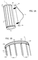
- Figures 1A to 1C show different perspective views of a possible embodiment of a modular lighting system 1 according to the present description.
- the lighting system 1 comprises lighting means, such as an LED module comprising at least one LED, and a housing.
- the housing of the lighting system 1 may be formed by a cooling body 14 comprising in the longitudinal direction a plurality of channels or ducts 140 for the passage of air.
- the cooling body 14 has a tubular shape, i.e. the cooling body comprises axially respective openings, wherein the cooling body 14 has on its external surface the channels 140. It is preferable for the ducts 140 to be arranged in an equidistant manner.
- the cooling body 14 may comprise a duct 140 for each side of the polygon, preferably arranged in the center of the respective side.
- ducts 140 arranged radially.
- the cooling body 14 is formed as one piece, for example by means of an extrusion process.
- the LED module is mounted on the inside of the cooling body 14, preferably in the proximity of one of the openings, for example on the bottom side in figure 1A .
- the LED module may be mounted on a printed circuit having a circular cross section which is fixed, for example by means of a joining system or fixing means, to the inside of the cooling body 14.
- the LED module can be mounted on a support made of a material with a high heat dissipation coefficient.
- the lighting system 1 comprises a transparent cover 16 intended to close the cooling body 14 axially on a first side, i.e. on the bottom side in figure 1A .
- this cover 16 has an internal surface and an external surface, wherein the cover 16 closes with its internal surface the opening in the cooling body 14.
- this cover 16 can be fixed, for example by means of joining or screws, to the bottom edge of the cooling body 14.
- this cover 16 does not necessarily have to be transparent, but may also be made of colored plastic or of various materials with different finishes.
- the lighting system 1 comprises a reflector for focusing the light generated by the LED module. It is preferable for this reflector to be arranged between the LED module and the cover 16.
- the reflector may have a circular cross section.
- the lighting system also comprises a drive circuit 20 for the LED module, such as an electronic converter.
- This drive circuit may be mounted directly on the printed circuit of the LED module or, for example in the case in which this drive circuit 20 comprises a transformer, the drive circuit 20 may be mounted on a separate printed circuit.
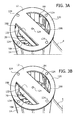
- this drive circuit 20 is also mounted on the inside of the cooling body (see for example figure 3A ).
- the drive circuit 20 is mounted on the inside of a rectangular housing, which in turn is fixed to the inside of the cooling body 14, preferably in the proximity of the top opening in the cooling body 14.
- the lighting system 1 also comprises a second cover 12 intended to close the cooling body 14 axially on the top side in figure 1A .
- this cover 12 has an internal surface and an external surface, wherein the cover 12 closes with its internal surface the opening in the cooling body 14.
- the cover 12 is fixed by means of screws 124 to the top edge of the cooling body 14.
- this cover it is not necessary for this cover to be solid, but rather it is sufficient for the cover 12 to comprise a frame structure 120 which corresponds substantially to the cross section of the cooling body 14.
- this frame structure 120 has an annular shape.
- the cover 12 also comprises a rectangular portion 122 intended to close the housing of the drive circuit 20.
- part of the cooling body 14 may also remain open.
- this may be advantageous for allowing the passage of air and for avoiding excessive heating of the drive circuit 20.
- these profiled elements 4 comprise a first engagement formation 40 which is inserted in one of the channels 140 and a second engagement formation 42 configured for cooperating with corresponding formations in the housing of the lighting system 1.
- figure 1B shows an embodiment in which the cover 12 comprises on its bottom side, i.e. the side which closes the cooling body 14, a plurality of seats 126, such as cavities, or blind holes or through-holes. It is preferable for these seats 126 to be arranged in correspondence with the ducts 140. By way of example, in the embodiment considered, these seats 126 are arranged in the frame structure 120 along an internal circumference line.
- each additional element 4 comprises a second engagement formation 42 which is complementary to the shape of the seats 126.
- this second engagement formation 42 is a protrusion, such as a plate or a pin.
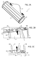
- the first engagement formation 40 of the additional element 4 is first inserted in one of the longitudinal ducts 140 of the housing and then pushed in the direction of the cover 12 (see for example figures 2A and 2B ). Consequently, the second engagement formation 42 of the element 4 is inserted in the seat 126 associated with the respective duct 140.
- the additional element 4 is blocked radially by means of the side walls of the channels 140 and laterally by means of the coupling between the second engagement formations 42 and the seats 126.
- the first engagement formation 40 may have a thickness which corresponds substantially to the width of a duct 140.
- the element is still movable in the longitudinal direction. Therefore, in one embodiment, provision is also made of a blocking mechanism which blocks the movement of the additional element 4 in the longitudinal direction.
- this blocking mechanism may be formed by simple wedge formations which are activated when the second engagement formation 42 of the element 4 is inserted in the seat 126. Nevertheless, the inventors have realized that these wedge systems are not always sufficient and/or their use is not always easy.
- this blocking ring comprises incisions 182 in correspondence with the channels 140 and the first engagement formation 40, i.e. the portion of the additional element 4 which is inserted in the channel 140, comprises a cavity 44, such as an incision.
- this blocking ring 18 may be moved at least into a first operative position, in which the incisions 182 are positioned in correspondence with the channels 140, and a second operative position, in which a portion of the edge of the blocking ring 18 covers a portion of the channels 140, thereby ensuring that the additional element 4 cannot be pulled out in the longitudinal direction.
- this blocking ring 18 may also comprise formations 184, such as protrusions, which can be used as handles for making the rotation of the blocking ring 18 easier.
- the blocking ring 18 may comprise wedge formations 186 which cooperate with respective formations in the cover 12 for blocking the rotation of the blocking ring 18 in the first and/or second operative position.
- the additional elements 4 also comprise further formations which cooperate with respective formations in the housing of the lighting system 1, for example formations in the cooling body 14 and/or the cover 16.
- the additional element 4 comprises a third engagement formation 46, such as a hook-shaped protrusion, configured to cooperate with the bottom edge of the cooling body 14. Consequently, when the additional element 4 is inserted in a duct 140 and the additional element is pushed upward, the third engagement formations 46 are hooked to the edge of the cooling body 14, further blocking the additional element 4 in the lateral direction.
- a third engagement formation 46 such as a hook-shaped protrusion
- the transparent cover 16 may comprise, in this respect, lateral openings 162 arranged in correspondence with the ducts 140, these openings making it possible for the third engagement formations 46 to be inserted underneath the bottom edge of the cooling body 14.
- the covers 12 can also be realized by the transparent cover 16.
- the seats 126 are arranged in the cover 16 and, for blocking the additional element 4, the additional element 4 is pushed downward. Consequently, the blocking ring 18 could also be arranged between the cover 16 and the bottom edge of the cooling body 14.
- the channels 140 are used not only to improve the cooling, but also to improve the stability of assembly of the additional elements 4. Moreover, in the case where additional elements 4 are not fixed to the lighting system 1, external fixing elements are not visible.
- the additional element 4 may:
- the fastening system described here provides the apparatus with spatial characteristics of structural stability both in the same plane or by expanding the structure in different planes which may also not be parallel to each other.
- the fixing points may be rigid and/or hung from surfaces (e.g. walls, ceilings) and/or other structures (e.g. secondary optical systems).
- assembly may also be performed only at the final destination, which simplifies the transportation logistics, considering the packaging - individual and/or in kit form - both of the single sources and of the interconnecting elements.
- the basic lighting system may be reused, thus allowing the costs of the apparatus to be minimized, by taking advantage of the low costs for production of predefined components.
Landscapes
- Engineering & Computer Science (AREA)
- General Engineering & Computer Science (AREA)
- Arrangement Of Elements, Cooling, Sealing, Or The Like Of Lighting Devices (AREA)
- Non-Portable Lighting Devices Or Systems Thereof (AREA)
- Lasers (AREA)
Applications Claiming Priority (1)
| Application Number | Priority Date | Filing Date | Title |
|---|---|---|---|
| IT000954A ITTO20110954A1 (it) | 2011-10-21 | 2011-10-21 | Sistema di illuminazione |
Publications (2)
| Publication Number | Publication Date |
|---|---|
| EP2584252A1 EP2584252A1 (en) | 2013-04-24 |
| EP2584252B1 true EP2584252B1 (en) | 2015-02-25 |
Family
ID=45470651
Family Applications (1)
| Application Number | Title | Priority Date | Filing Date |
|---|---|---|---|
| EP12187910.0A Not-in-force EP2584252B1 (en) | 2011-10-21 | 2012-10-10 | Lighting system |
Country Status (4)
| Country | Link |
|---|---|
| US (1) | US9163809B2 (it) |
| EP (1) | EP2584252B1 (it) |
| CN (1) | CN103104831A (it) |
| IT (1) | ITTO20110954A1 (it) |
Families Citing this family (3)
| Publication number | Priority date | Publication date | Assignee | Title |
|---|---|---|---|---|
| FI125617B (en) * | 2013-07-04 | 2015-12-15 | Lumitar Array Lighting Technology Finland Ab | Heat Transfer Profile |
| JP6365978B2 (ja) * | 2014-09-12 | 2018-08-01 | パナソニックIpマネジメント株式会社 | 照明装置、及びその取付構造 |
| WO2018102024A1 (en) * | 2016-12-02 | 2018-06-07 | Cooper Technologies Company | Antennae for hazardous location light fixtures |
Family Cites Families (17)
| Publication number | Priority date | Publication date | Assignee | Title |
|---|---|---|---|---|
| US3116022A (en) * | 1960-05-26 | 1963-12-31 | Ariel R Davis | Spotlight |
| US7097332B2 (en) * | 2003-09-05 | 2006-08-29 | Gabor Vamberi | Light fixture with fins |
| US7226183B2 (en) * | 2005-06-28 | 2007-06-05 | Robert D. Galli | Flashlight having mating formations for integration with a rail mounting system |
| US20080089071A1 (en) * | 2006-10-12 | 2008-04-17 | Chin-Wen Wang | Lamp structure with adjustable projection angle |
| DE102007009548A1 (de) * | 2007-02-27 | 2008-08-28 | Siteco Beleuchtungstechnik Gmbh | Verschluß-System für eine Leuchtenabdeckung |
| US8226270B2 (en) * | 2007-05-23 | 2012-07-24 | Sharp Kabushiki Kaisha | Lighting device |
| DE102007045555A1 (de) * | 2007-09-24 | 2009-04-02 | Ledon Lighting Gmbh | Kühlkörper und Kühlsystem für ein LED-Modul |
| US7695162B2 (en) * | 2007-12-27 | 2010-04-13 | Fu Zhun Precision Industry (Shen Zhen) Co., Ltd. | LED lamp having a plurality of heat sinks |
| US20090185380A1 (en) * | 2008-01-17 | 2009-07-23 | Ho Sung Tao | LED Lamp with Heat Dissipating Configuration |
| US7806564B2 (en) * | 2008-03-12 | 2010-10-05 | Aeon Lighting Technology Inc. | Connection device of an LED lamp and cooling fins |
| US8083370B2 (en) * | 2008-05-09 | 2011-12-27 | The Sloan Company, Inc. | Low profile extrusion |
| US7874690B2 (en) * | 2008-06-24 | 2011-01-25 | Tyco Electronics Corporation | LED lighting fixture for illuminating a cavity |
| US8317369B2 (en) * | 2009-04-02 | 2012-11-27 | Abl Ip Holding Llc | Light fixture having selectively positionable housing |
| US8033687B2 (en) * | 2009-06-26 | 2011-10-11 | Pyroswift Holding Co., Limited | Waterproof assembly of LED lamp cup |
| US20110051430A1 (en) * | 2009-08-25 | 2011-03-03 | Shih-Ming Chen | Assembly structure for led fixture |
| US20110216546A1 (en) * | 2010-03-03 | 2011-09-08 | Leviton Manufacturing Co., Inc. | Lampholder with occupancy sensor |
| IT1404534B1 (it) * | 2011-02-25 | 2013-11-22 | Osram Spa | Sistema di illuminazione. |
-
2011
- 2011-10-21 IT IT000954A patent/ITTO20110954A1/it unknown
-
2012
- 2012-10-10 EP EP12187910.0A patent/EP2584252B1/en not_active Not-in-force
- 2012-10-19 US US13/655,479 patent/US9163809B2/en not_active Expired - Fee Related
- 2012-10-19 CN CN201210400702XA patent/CN103104831A/zh active Pending
Also Published As
| Publication number | Publication date |
|---|---|
| US9163809B2 (en) | 2015-10-20 |
| US20130100669A1 (en) | 2013-04-25 |
| CN103104831A (zh) | 2013-05-15 |
| ITTO20110954A1 (it) | 2013-04-22 |
| EP2584252A1 (en) | 2013-04-24 |
Similar Documents
| Publication | Publication Date | Title |
|---|---|---|
| USD561374S1 (en) | Light fixture | |
| US9523490B2 (en) | Reflectors and reflector orientation feature to prevent non-qualified trim | |
| USD641520S1 (en) | LED downlight with trim and spacers | |
| USD869082S1 (en) | Lighting fixture | |
| USD575438S1 (en) | Lighting fixture | |
| EP2584252B1 (en) | Lighting system | |
| EP3106743B1 (en) | Luminaire modular surface covering arrangement and luminaire kit | |
| KR20170000511U (ko) | 시스템 조명등기구 | |
| USD580589S1 (en) | Curved lamp pole for an outdoor lighting fixture | |
| USD639415S1 (en) | Combination ceiling fan and light fixture, combining upper and downward lighting | |
| JP6851984B2 (ja) | 照明器具のための繰返し可能なルーバ・アクセサリ | |
| KR20160101657A (ko) | 다기능 액자 | |
| WO2012113772A2 (en) | Lighting system | |
| KR101777162B1 (ko) | 분할 조립성과 장식성을 갖는 천정직착등 | |
| CN110573793A (zh) | 组装灯具的套件和方法 | |
| KR102613482B1 (ko) | 방사형 장식구조를 포함하는 거울 | |
| KR200442382Y1 (ko) | 형광등기구의 반사갓과 덮개의 체결구조 | |
| KR100660439B1 (ko) | 장식용 조명기구의 전등커버 | |
| KR102536789B1 (ko) | 다채색 간접조명을 할 수 있는 엘이디 조명등기구 | |
| KR200376133Y1 (ko) | 팬던트형 조명기구 | |
| KR101475435B1 (ko) | 건축 몰딩 마감재용 조명 장치 | |
| KR200459190Y1 (ko) | 조명장치 | |
| KR200362105Y1 (ko) | 천정등의 투광장식재 조립구조 | |
| JP2005129426A (ja) | 装飾照明装置 | |
| JP2015032400A (ja) | 照明装置 |
Legal Events
| Date | Code | Title | Description |
|---|---|---|---|
| PUAI | Public reference made under article 153(3) epc to a published international application that has entered the european phase |
Free format text: ORIGINAL CODE: 0009012 |
|
| AK | Designated contracting states |
Kind code of ref document: A1 Designated state(s): AL AT BE BG CH CY CZ DE DK EE ES FI FR GB GR HR HU IE IS IT LI LT LU LV MC MK MT NL NO PL PT RO RS SE SI SK SM TR |
|
| AX | Request for extension of the european patent |
Extension state: BA ME |
|
| 17P | Request for examination filed |
Effective date: 20131024 |
|
| RBV | Designated contracting states (corrected) |
Designated state(s): AL AT BE BG CH CY CZ DE DK EE ES FI FR GB GR HR HU IE IS IT LI LT LU LV MC MK MT NL NO PL PT RO RS SE SI SK SM TR |
|
| 17Q | First examination report despatched |
Effective date: 20140703 |
|
| GRAP | Despatch of communication of intention to grant a patent |
Free format text: ORIGINAL CODE: EPIDOSNIGR1 |
|
| RIC1 | Information provided on ipc code assigned before grant |
Ipc: F21V 29/00 20060101ALN20140922BHEP Ipc: F21V 17/10 20060101ALI20140922BHEP Ipc: F21V 15/01 20060101AFI20140922BHEP Ipc: F21Y 101/02 20060101ALN20140922BHEP |
|
| INTG | Intention to grant announced |
Effective date: 20141028 |
|
| GRAS | Grant fee paid |
Free format text: ORIGINAL CODE: EPIDOSNIGR3 |
|
| GRAA | (expected) grant |
Free format text: ORIGINAL CODE: 0009210 |
|
| AK | Designated contracting states |
Kind code of ref document: B1 Designated state(s): AL AT BE BG CH CY CZ DE DK EE ES FI FR GB GR HR HU IE IS IT LI LT LU LV MC MK MT NL NO PL PT RO RS SE SI SK SM TR |
|
| REG | Reference to a national code |
Ref country code: GB Ref legal event code: FG4D |
|
| REG | Reference to a national code |
Ref country code: CH Ref legal event code: EP |
|
| REG | Reference to a national code |
Ref country code: IE Ref legal event code: FG4D |
|
| REG | Reference to a national code |
Ref country code: DE Ref legal event code: R096 Ref document number: 602012005420 Country of ref document: DE Effective date: 20150409 |
|
| REG | Reference to a national code |
Ref country code: AT Ref legal event code: REF Ref document number: 712303 Country of ref document: AT Kind code of ref document: T Effective date: 20150415 |
|
| REG | Reference to a national code |
Ref country code: NL Ref legal event code: VDEP Effective date: 20150225 |
|
| REG | Reference to a national code |
Ref country code: LT Ref legal event code: MG4D |
|
| PG25 | Lapsed in a contracting state [announced via postgrant information from national office to epo] |
Ref country code: NO Free format text: LAPSE BECAUSE OF FAILURE TO SUBMIT A TRANSLATION OF THE DESCRIPTION OR TO PAY THE FEE WITHIN THE PRESCRIBED TIME-LIMIT Effective date: 20150525 Ref country code: ES Free format text: LAPSE BECAUSE OF FAILURE TO SUBMIT A TRANSLATION OF THE DESCRIPTION OR TO PAY THE FEE WITHIN THE PRESCRIBED TIME-LIMIT Effective date: 20150225 Ref country code: SE Free format text: LAPSE BECAUSE OF FAILURE TO SUBMIT A TRANSLATION OF THE DESCRIPTION OR TO PAY THE FEE WITHIN THE PRESCRIBED TIME-LIMIT Effective date: 20150225 Ref country code: LT Free format text: LAPSE BECAUSE OF FAILURE TO SUBMIT A TRANSLATION OF THE DESCRIPTION OR TO PAY THE FEE WITHIN THE PRESCRIBED TIME-LIMIT Effective date: 20150225 Ref country code: HR Free format text: LAPSE BECAUSE OF FAILURE TO SUBMIT A TRANSLATION OF THE DESCRIPTION OR TO PAY THE FEE WITHIN THE PRESCRIBED TIME-LIMIT Effective date: 20150225 Ref country code: FI Free format text: LAPSE BECAUSE OF FAILURE TO SUBMIT A TRANSLATION OF THE DESCRIPTION OR TO PAY THE FEE WITHIN THE PRESCRIBED TIME-LIMIT Effective date: 20150225 |
|
| PG25 | Lapsed in a contracting state [announced via postgrant information from national office to epo] |
Ref country code: LV Free format text: LAPSE BECAUSE OF FAILURE TO SUBMIT A TRANSLATION OF THE DESCRIPTION OR TO PAY THE FEE WITHIN THE PRESCRIBED TIME-LIMIT Effective date: 20150225 Ref country code: IS Free format text: LAPSE BECAUSE OF FAILURE TO SUBMIT A TRANSLATION OF THE DESCRIPTION OR TO PAY THE FEE WITHIN THE PRESCRIBED TIME-LIMIT Effective date: 20150625 Ref country code: RS Free format text: LAPSE BECAUSE OF FAILURE TO SUBMIT A TRANSLATION OF THE DESCRIPTION OR TO PAY THE FEE WITHIN THE PRESCRIBED TIME-LIMIT Effective date: 20150225 Ref country code: GR Free format text: LAPSE BECAUSE OF FAILURE TO SUBMIT A TRANSLATION OF THE DESCRIPTION OR TO PAY THE FEE WITHIN THE PRESCRIBED TIME-LIMIT Effective date: 20150526 |
|
| PG25 | Lapsed in a contracting state [announced via postgrant information from national office to epo] |
Ref country code: NL Free format text: LAPSE BECAUSE OF FAILURE TO SUBMIT A TRANSLATION OF THE DESCRIPTION OR TO PAY THE FEE WITHIN THE PRESCRIBED TIME-LIMIT Effective date: 20150225 |
|
| PG25 | Lapsed in a contracting state [announced via postgrant information from national office to epo] |
Ref country code: SK Free format text: LAPSE BECAUSE OF FAILURE TO SUBMIT A TRANSLATION OF THE DESCRIPTION OR TO PAY THE FEE WITHIN THE PRESCRIBED TIME-LIMIT Effective date: 20150225 Ref country code: EE Free format text: LAPSE BECAUSE OF FAILURE TO SUBMIT A TRANSLATION OF THE DESCRIPTION OR TO PAY THE FEE WITHIN THE PRESCRIBED TIME-LIMIT Effective date: 20150225 Ref country code: RO Free format text: LAPSE BECAUSE OF FAILURE TO SUBMIT A TRANSLATION OF THE DESCRIPTION OR TO PAY THE FEE WITHIN THE PRESCRIBED TIME-LIMIT Effective date: 20150225 Ref country code: CZ Free format text: LAPSE BECAUSE OF FAILURE TO SUBMIT A TRANSLATION OF THE DESCRIPTION OR TO PAY THE FEE WITHIN THE PRESCRIBED TIME-LIMIT Effective date: 20150225 Ref country code: DK Free format text: LAPSE BECAUSE OF FAILURE TO SUBMIT A TRANSLATION OF THE DESCRIPTION OR TO PAY THE FEE WITHIN THE PRESCRIBED TIME-LIMIT Effective date: 20150225 |
|
| REG | Reference to a national code |
Ref country code: DE Ref legal event code: R097 Ref document number: 602012005420 Country of ref document: DE |
|
| PG25 | Lapsed in a contracting state [announced via postgrant information from national office to epo] |
Ref country code: PL Free format text: LAPSE BECAUSE OF FAILURE TO SUBMIT A TRANSLATION OF THE DESCRIPTION OR TO PAY THE FEE WITHIN THE PRESCRIBED TIME-LIMIT Effective date: 20150225 |
|
| PG25 | Lapsed in a contracting state [announced via postgrant information from national office to epo] |
Ref country code: IT Free format text: LAPSE BECAUSE OF FAILURE TO SUBMIT A TRANSLATION OF THE DESCRIPTION OR TO PAY THE FEE WITHIN THE PRESCRIBED TIME-LIMIT Effective date: 20150225 |
|
| PLBE | No opposition filed within time limit |
Free format text: ORIGINAL CODE: 0009261 |
|
| STAA | Information on the status of an ep patent application or granted ep patent |
Free format text: STATUS: NO OPPOSITION FILED WITHIN TIME LIMIT |
|
| 26N | No opposition filed |
Effective date: 20151126 |
|
| PG25 | Lapsed in a contracting state [announced via postgrant information from national office to epo] |
Ref country code: SI Free format text: LAPSE BECAUSE OF FAILURE TO SUBMIT A TRANSLATION OF THE DESCRIPTION OR TO PAY THE FEE WITHIN THE PRESCRIBED TIME-LIMIT Effective date: 20150225 |
|
| PG25 | Lapsed in a contracting state [announced via postgrant information from national office to epo] |
Ref country code: LU Free format text: LAPSE BECAUSE OF FAILURE TO SUBMIT A TRANSLATION OF THE DESCRIPTION OR TO PAY THE FEE WITHIN THE PRESCRIBED TIME-LIMIT Effective date: 20151010 Ref country code: BE Free format text: LAPSE BECAUSE OF FAILURE TO SUBMIT A TRANSLATION OF THE DESCRIPTION OR TO PAY THE FEE WITHIN THE PRESCRIBED TIME-LIMIT Effective date: 20150225 |
|
| REG | Reference to a national code |
Ref country code: CH Ref legal event code: PL |
|
| PG25 | Lapsed in a contracting state [announced via postgrant information from national office to epo] |
Ref country code: MC Free format text: LAPSE BECAUSE OF FAILURE TO SUBMIT A TRANSLATION OF THE DESCRIPTION OR TO PAY THE FEE WITHIN THE PRESCRIBED TIME-LIMIT Effective date: 20150225 |
|
| REG | Reference to a national code |
Ref country code: IE Ref legal event code: MM4A |
|
| PG25 | Lapsed in a contracting state [announced via postgrant information from national office to epo] |
Ref country code: LI Free format text: LAPSE BECAUSE OF NON-PAYMENT OF DUE FEES Effective date: 20151031 Ref country code: CH Free format text: LAPSE BECAUSE OF NON-PAYMENT OF DUE FEES Effective date: 20151031 |
|
| REG | Reference to a national code |
Ref country code: FR Ref legal event code: ST Effective date: 20160630 |
|
| PG25 | Lapsed in a contracting state [announced via postgrant information from national office to epo] |
Ref country code: FR Free format text: LAPSE BECAUSE OF NON-PAYMENT OF DUE FEES Effective date: 20151102 |
|
| PG25 | Lapsed in a contracting state [announced via postgrant information from national office to epo] |
Ref country code: IE Free format text: LAPSE BECAUSE OF NON-PAYMENT OF DUE FEES Effective date: 20151010 |
|
| PG25 | Lapsed in a contracting state [announced via postgrant information from national office to epo] |
Ref country code: BG Free format text: LAPSE BECAUSE OF FAILURE TO SUBMIT A TRANSLATION OF THE DESCRIPTION OR TO PAY THE FEE WITHIN THE PRESCRIBED TIME-LIMIT Effective date: 20150225 Ref country code: SM Free format text: LAPSE BECAUSE OF FAILURE TO SUBMIT A TRANSLATION OF THE DESCRIPTION OR TO PAY THE FEE WITHIN THE PRESCRIBED TIME-LIMIT Effective date: 20150225 Ref country code: HU Free format text: LAPSE BECAUSE OF FAILURE TO SUBMIT A TRANSLATION OF THE DESCRIPTION OR TO PAY THE FEE WITHIN THE PRESCRIBED TIME-LIMIT; INVALID AB INITIO Effective date: 20121010 |
|
| GBPC | Gb: european patent ceased through non-payment of renewal fee |
Effective date: 20161010 |
|
| PG25 | Lapsed in a contracting state [announced via postgrant information from national office to epo] |
Ref country code: CY Free format text: LAPSE BECAUSE OF FAILURE TO SUBMIT A TRANSLATION OF THE DESCRIPTION OR TO PAY THE FEE WITHIN THE PRESCRIBED TIME-LIMIT Effective date: 20150225 |
|
| PG25 | Lapsed in a contracting state [announced via postgrant information from national office to epo] |
Ref country code: GB Free format text: LAPSE BECAUSE OF NON-PAYMENT OF DUE FEES Effective date: 20161010 |
|
| PG25 | Lapsed in a contracting state [announced via postgrant information from national office to epo] |
Ref country code: MT Free format text: LAPSE BECAUSE OF FAILURE TO SUBMIT A TRANSLATION OF THE DESCRIPTION OR TO PAY THE FEE WITHIN THE PRESCRIBED TIME-LIMIT Effective date: 20150225 |
|
| REG | Reference to a national code |
Ref country code: AT Ref legal event code: UEP Ref document number: 712303 Country of ref document: AT Kind code of ref document: T Effective date: 20150225 |
|
| PGFP | Annual fee paid to national office [announced via postgrant information from national office to epo] |
Ref country code: DE Payment date: 20171019 Year of fee payment: 6 |
|
| PGFP | Annual fee paid to national office [announced via postgrant information from national office to epo] |
Ref country code: AT Payment date: 20171020 Year of fee payment: 6 |
|
| PG25 | Lapsed in a contracting state [announced via postgrant information from national office to epo] |
Ref country code: TR Free format text: LAPSE BECAUSE OF FAILURE TO SUBMIT A TRANSLATION OF THE DESCRIPTION OR TO PAY THE FEE WITHIN THE PRESCRIBED TIME-LIMIT Effective date: 20150225 Ref country code: PT Free format text: LAPSE BECAUSE OF FAILURE TO SUBMIT A TRANSLATION OF THE DESCRIPTION OR TO PAY THE FEE WITHIN THE PRESCRIBED TIME-LIMIT Effective date: 20150225 Ref country code: MK Free format text: LAPSE BECAUSE OF FAILURE TO SUBMIT A TRANSLATION OF THE DESCRIPTION OR TO PAY THE FEE WITHIN THE PRESCRIBED TIME-LIMIT Effective date: 20150225 |
|
| PG25 | Lapsed in a contracting state [announced via postgrant information from national office to epo] |
Ref country code: AL Free format text: LAPSE BECAUSE OF FAILURE TO SUBMIT A TRANSLATION OF THE DESCRIPTION OR TO PAY THE FEE WITHIN THE PRESCRIBED TIME-LIMIT Effective date: 20150225 |
|
| RIC2 | Information provided on ipc code assigned after grant |
Ipc: F21V 17/10 20060101ALI20140922BHEP Ipc: F21V 29/00 20150101ALN20140922BHEP Ipc: F21Y 101/02 20000101ALN20140922BHEP Ipc: F21V 15/01 20060101AFI20140922BHEP |
|
| REG | Reference to a national code |
Ref country code: DE Ref legal event code: R119 Ref document number: 602012005420 Country of ref document: DE |
|
| REG | Reference to a national code |
Ref country code: AT Ref legal event code: MM01 Ref document number: 712303 Country of ref document: AT Kind code of ref document: T Effective date: 20181010 |
|
| PG25 | Lapsed in a contracting state [announced via postgrant information from national office to epo] |
Ref country code: DE Free format text: LAPSE BECAUSE OF NON-PAYMENT OF DUE FEES Effective date: 20190501 |
|
| PG25 | Lapsed in a contracting state [announced via postgrant information from national office to epo] |
Ref country code: AT Free format text: LAPSE BECAUSE OF NON-PAYMENT OF DUE FEES Effective date: 20181010 |