EP2584274A2 - Unité d'intérieur de climatiseur - Google Patents
Unité d'intérieur de climatiseur Download PDFInfo
- Publication number
- EP2584274A2 EP2584274A2 EP12151196.8A EP12151196A EP2584274A2 EP 2584274 A2 EP2584274 A2 EP 2584274A2 EP 12151196 A EP12151196 A EP 12151196A EP 2584274 A2 EP2584274 A2 EP 2584274A2
- Authority
- EP
- European Patent Office
- Prior art keywords
- indoor unit
- heat exchanger
- frame
- fan
- air
- Prior art date
- Legal status (The legal status is an assumption and is not a legal conclusion. Google has not performed a legal analysis and makes no representation as to the accuracy of the status listed.)
- Withdrawn
Links
- 238000001914 filtration Methods 0.000 claims description 4
- XLYOFNOQVPJJNP-UHFFFAOYSA-N water Substances O XLYOFNOQVPJJNP-UHFFFAOYSA-N 0.000 claims description 4
- 238000010168 coupling process Methods 0.000 description 5
- 238000000034 method Methods 0.000 description 5
- 230000004308 accommodation Effects 0.000 description 4
- 230000000903 blocking effect Effects 0.000 description 4
- 230000008878 coupling Effects 0.000 description 4
- 238000005859 coupling reaction Methods 0.000 description 4
- 238000012986 modification Methods 0.000 description 3
- 230000004048 modification Effects 0.000 description 3
- 238000001816 cooling Methods 0.000 description 2
- 230000007423 decrease Effects 0.000 description 2
- 238000005452 bending Methods 0.000 description 1
- 230000003247 decreasing effect Effects 0.000 description 1
- 238000007599 discharging Methods 0.000 description 1
- 239000000428 dust Substances 0.000 description 1
- 230000000694 effects Effects 0.000 description 1
- 238000009434 installation Methods 0.000 description 1
- 239000003507 refrigerant Substances 0.000 description 1
- 230000000630 rising effect Effects 0.000 description 1
- 239000000126 substance Substances 0.000 description 1
Images


Classifications
-
- F—MECHANICAL ENGINEERING; LIGHTING; HEATING; WEAPONS; BLASTING
- F24—HEATING; RANGES; VENTILATING
- F24F—AIR-CONDITIONING; AIR-HUMIDIFICATION; VENTILATION; USE OF AIR CURRENTS FOR SCREENING
- F24F1/00—Room units for air-conditioning, e.g. separate or self-contained units or units receiving primary air from a central station
- F24F1/0007—Indoor units, e.g. fan coil units
- F24F1/0011—Indoor units, e.g. fan coil units characterised by air outlets
-
- F—MECHANICAL ENGINEERING; LIGHTING; HEATING; WEAPONS; BLASTING
- F24—HEATING; RANGES; VENTILATING
- F24F—AIR-CONDITIONING; AIR-HUMIDIFICATION; VENTILATION; USE OF AIR CURRENTS FOR SCREENING
- F24F1/00—Room units for air-conditioning, e.g. separate or self-contained units or units receiving primary air from a central station
- F24F1/0007—Indoor units, e.g. fan coil units
- F24F1/0043—Indoor units, e.g. fan coil units characterised by mounting arrangements
- F24F1/0057—Indoor units, e.g. fan coil units characterised by mounting arrangements mounted in or on a wall
-
- F—MECHANICAL ENGINEERING; LIGHTING; HEATING; WEAPONS; BLASTING
- F24—HEATING; RANGES; VENTILATING
- F24F—AIR-CONDITIONING; AIR-HUMIDIFICATION; VENTILATION; USE OF AIR CURRENTS FOR SCREENING
- F24F1/00—Room units for air-conditioning, e.g. separate or self-contained units or units receiving primary air from a central station
- F24F1/0007—Indoor units, e.g. fan coil units
- F24F1/0059—Indoor units, e.g. fan coil units characterised by heat exchangers
- F24F1/0063—Indoor units, e.g. fan coil units characterised by heat exchangers by the mounting or arrangement of the heat exchangers
-
- F—MECHANICAL ENGINEERING; LIGHTING; HEATING; WEAPONS; BLASTING
- F24—HEATING; RANGES; VENTILATING
- F24F—AIR-CONDITIONING; AIR-HUMIDIFICATION; VENTILATION; USE OF AIR CURRENTS FOR SCREENING
- F24F1/00—Room units for air-conditioning, e.g. separate or self-contained units or units receiving primary air from a central station
- F24F1/0007—Indoor units, e.g. fan coil units
- F24F1/0059—Indoor units, e.g. fan coil units characterised by heat exchangers
- F24F1/0067—Indoor units, e.g. fan coil units characterised by heat exchangers by the shape of the heat exchangers or of parts thereof, e.g. of their fins
-
- F—MECHANICAL ENGINEERING; LIGHTING; HEATING; WEAPONS; BLASTING
- F24—HEATING; RANGES; VENTILATING
- F24F—AIR-CONDITIONING; AIR-HUMIDIFICATION; VENTILATION; USE OF AIR CURRENTS FOR SCREENING
- F24F1/00—Room units for air-conditioning, e.g. separate or self-contained units or units receiving primary air from a central station
- F24F1/0007—Indoor units, e.g. fan coil units
- F24F1/0071—Indoor units, e.g. fan coil units with means for purifying supplied air
- F24F1/0073—Indoor units, e.g. fan coil units with means for purifying supplied air characterised by the mounting or arrangement of filters
-
- F—MECHANICAL ENGINEERING; LIGHTING; HEATING; WEAPONS; BLASTING
- F24—HEATING; RANGES; VENTILATING
- F24F—AIR-CONDITIONING; AIR-HUMIDIFICATION; VENTILATION; USE OF AIR CURRENTS FOR SCREENING
- F24F13/00—Details common to, or for air-conditioning, air-humidification, ventilation or use of air currents for screening
- F24F13/20—Casings or covers
-
- F—MECHANICAL ENGINEERING; LIGHTING; HEATING; WEAPONS; BLASTING
- F24—HEATING; RANGES; VENTILATING
- F24F—AIR-CONDITIONING; AIR-HUMIDIFICATION; VENTILATION; USE OF AIR CURRENTS FOR SCREENING
- F24F13/00—Details common to, or for air-conditioning, air-humidification, ventilation or use of air currents for screening
- F24F13/22—Means for preventing condensation or evacuating condensate
- F24F13/222—Means for preventing condensation or evacuating condensate for evacuating condensate
-
- F—MECHANICAL ENGINEERING; LIGHTING; HEATING; WEAPONS; BLASTING
- F24—HEATING; RANGES; VENTILATING
- F24F—AIR-CONDITIONING; AIR-HUMIDIFICATION; VENTILATION; USE OF AIR CURRENTS FOR SCREENING
- F24F13/00—Details common to, or for air-conditioning, air-humidification, ventilation or use of air currents for screening
- F24F13/28—Arrangement or mounting of filters
Definitions
- the present disclosure relates to an indoor unit of an air conditioner.
- Air conditioners perform a refrigerant cycle by means of a compressor, a condenser, an expansion device, and an evaporator to heat/cool an indoor space or purify air, thereby providing comforting indoor environment to users.
- Air conditioners are classified into air conditioners in which a single indoor unit is connected to a single outdoor unit, and multi-type air conditioners in which air conditioners are connected to one or more outdoor units to provide the effect of a plurality of air conditioners.
- An indoor unit of an air conditioner comprises a chassis and a frame coupled to the front of the chassis.
- the chassis supports a heat exchanger, and guides air flow.
- the frame is provided with an intake port and a discharge port.
- the intake port is disposed at the upper side of the indoor unit, and the discharge port is disposed at the lower side thereof.
- the intake port is disposed at the upper side of the indoor unit, dust formed on the intake port can be hidden from a user.
- the indoor unit is in cooling operation, the rising indoor warm air (higher in temperature than cooled air) is forcibly moved downward within the indoor unit opposing a natural air flow, and a flow rate of the air within the indoor unit may be decreased.
- cool air of low temperature is discharged from the lower side of the indoor unit, the cool air is discharged towards the floor, and thus, an indoor space may be unevenly cooled.
- Embodiments provide an indoor unit of an air conditioner.
- an indoor unit of an air conditioner comprises: an intake port to introduce air; a heat exchanger to exchange heat with the air introduced by the intake port; a fan moving the air; and a discharge port to discharge the air after exchanging heat with the heat exchanger, characterized in that the fan is disposed above the heat exchanger, the intake port is lower than a center of the fan, and the discharge port is higher than the center of the fan.
- FIG. 1 is a perspective view illustrating the front side of an indoor unit of an air conditioner according to a first embodiment.
- FIG. 2 is a perspective view illustrating the rear side of the indoor unit according to the first embodiment.
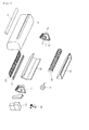
- FIG. 3 is an exploded perspective view illustrating the indoor unit according to the first embodiment.
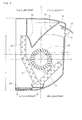
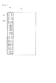
- FIG. 4 is a cross-sectional view illustrating the indoor unit according to the first embodiment.
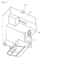
- FIG. 5 is a perspective view illustrating a control box according to the first embodiment.
- FIG. 6 is a perspective view illustrating a motor placed on the control box of FIG. 5 .
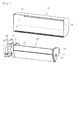
- FIG. 7 is a perspective view illustrating a process of assembling the indoor unit according to the first embodiment.
- FIG. 8 is a bottom view illustrating an indoor unit of an air conditioner according to a second embodiment.
- FIG. 9 is a cross-sectional view illustrating the indoor unit according to the second embodiment.
- FIG. 10 is a cross-sectional view illustrating a filter removed from the indoor unit of FIG. 9 .
- the indoor unit of a wall-mounted type air conditioner may be installed on a side wall in an indoor space, and be spaced apart from a floor and a ceiling in the indoor space.
- FIG. 1 is a perspective view illustrating the front side of an indoor unit of an air conditioner according to a first embodiment.
- FIG. 2 is a perspective view illustrating the rear side of the indoor unit according to the first embodiment.
- FIG. 3 is an exploded perspective view illustrating the indoor unit according to the first embodiment.
- an indoor unit 1 of an air conditioner may comprise: a frame 10 forming the appearance thereof; a heat exchanger 20 accommodated in the frame 10 and exchanging heat with introduced indoor air; a fan 40 moving the indoor air; a motor 30 rotating the fan 40; a flow guide 50 guiding air flow within the frame 10; a drain pan 60 collecting condensate water falling from the heat exchanger 20; and a control box 80 controlling the indoor unit 1.
- the frame 10 may form the front, both side, top, and bottom surfaces of the indoor unit 1. That is, the frame 10 has a rear opening. Although not shown, the rear opening may be covered with an installation panel for installing the indoor unit 1 on a wall.
- the bottom surface of the frame 10 is provided with an intake port 11 for introducing indoor air, and, according to the first embodiment, the front surface of the frame 10 is provided with a discharge port 12 for discharging the air after exchanging heat with the heat exchanger 20.
- the discharge port 12 is provided on the top surface of the frame 10. The intake port 11 is lower than the discharge port 12.
- the discharge port 12 may be disposed on the front upper portion of the frame 10, or be disposed on the top surface of the frame 10, or on the top and front surfaces of the frame 10.
- the discharge port 12 of the frame 10 is provided with a vane 13.
- the vane 13 may control the direction of discharged air.
- the frame 10 is provided with a filter 100 for filtering air introduced in the frame 10.
- the filter 100 is disposed at a downstream of the intake port 11.
- the filter 100 can filter air passing through the intake port 11.
- the filter 100 may be taken out through the rear opening of the frame 10.
- the lower surface of the frame 10 may be provided with a hole and a cover, so that the filter 100 can be inserted in and taken out from the frame 10 through the hole.
- the heat exchanger 20 may be bent at least one time to increase a heat exchange area, but is not limited thereto. Both sides of the heat exchanger 20 are coupled to supporters 71 and 72.
- the heat exchanger 20 is supported by the supporters 71 and 72.
- the supporters 71 and 72 comprise a first supporter (also denoted by 71) supporting a side portion of the heat exchanger 20, and a second supporter (also denoted by 72) supporting another side portion of the heat exchanger 20.
- the supporters 71 and 72 comprise heat exchanger seating parts 73, respectively, which have a shape to correspond with a side portion of the heat exchanger 20.
- the fan 40 may be a cross flow fan.
- the fan 40 may pass through the supporters 71 and 72.
- the supporters 71 and 72 may be provided with holes 74, so that the fan 40 can pass therethrough.
- the first supporter 71 may be provided with a hole to allow the fan 40 through
- the second supporter 72 may be provided with a seating part to seat the fan 40.
- At least one of the first and second supporters 71 and 72 may be provided with a coupled part 75 for coupling to the frame 10.
- a shaft of the motor 30 is connected to a side portion of the fan 40.
- the shaft of the motor 30 may pass through the hole of the first supporter 71.
- the motor 30 may be placed on the control box 80. Then, the motor 30 may be covered with a motor cover 90.
- FIG. 4 is a cross-sectional view illustrating the indoor unit according to the first embodiment.
- FIG. 4 correspond to the front and rear sides of the indoor unit 1, respectively.
- the heat exchanger 20 is disposed at the downstream of the intake port 11, and the fan 40 is disposed at a downstream of the heat exchanger 20. That is, when the fan 40 rotates, indoor air is introduced into the frame 10 through the intake port 11, then, passes through the heat exchanger 20, and then, flows to the fan 40.
- the indoor unit 1 may be divided into four regions by an X-axis and a Y-axis about a center C of the fan 40.
- the region disposed at the front upper side of the indoor unit 1 may be defined as a first quadrant, and the numbering may go counterclockwise starting from the first quadrant. That is, the second quadrant is disposed at the rear upper side of the indoor unit 1, the third quadrant is disposed at the rear lower side of the indoor unit 1, and the fourth quadrant is disposed at the front lower side of the indoor unit 1. Since the four regions are separated with respect to the center C of the fan 40, the area of the four regions may be varied by shifting the fan 40.
- the center C of the fan 40 is lower than a line L bisecting a height of the frame 10 (i.e., the indoor unit 1).
- the intake port 11 When the indoor unit 1 is divided into the four quadrants, at least one portion of the intake port 11 may be disposed in the third quadrant, and the discharge port 12 may be disposed in the first quadrant.
- the intake port 11 is disposed only in the third quadrant in FIG. 4 , the intake port 11 may be disposed in both the third and fourth quadrants. In this case, air introduced through the intake port 11 rises in the indoor unit 1, and flows to the front side of the indoor unit 1.
- the center C of the fan 40 is closer to the front surface of the indoor unit 1 (the front surface of the frame 10) than to the intake port 11.
- the intake port 11 is lower than the center C of the fan 40, and the discharge port 12 is higher than the center C of the fan 40.
- the fan 40 is higher than the intake port 11, and is lower than the discharge port 12.
- indoor air is higher in temperature than heat-exchanged air (hereinafter, referred to as cool air) in the indoor unit 1.
- cool air heat-exchanged air
- an intake port 11 and a discharge port 12 are disposed as described above, air of higher temperature is introduced from the lower side of an indoor unit, then, rises and undergoes heat exchange within the indoor unit, and then, is discharged forward from the upper portion of the indoor unit.
- the air can naturally flow within the indoor unit, thereby increasing a flow rate of the air within the indoor unit. That is, air flow within the indoor unit can be facilitated by using a movement of high temperature air.
- the heat exchanger 20 may comprise a first part 21, a second part 22, and a third part 23.
- the first to third parts 21 to 23 constituting the heat exchanger 20 may be separated according to the shape of the heat exchanger 20.
- the heat exchanger 20 may comprise separate first, second, and third heat exchangers.
- the first part 21 may form a predetermined angle with the second part 22, and the second part 22 may form a predetermined angle with the third part 23. At least one portion of the first part 21 may be disposed in the fourth quadrant. At least one portion of the second part 22 may be disposed in the third quadrant. At least one portion of the third part 23 may be disposed in the second quadrant.
- At least one of the first and third parts 21 and 23 may be removed.
- the heat exchanger 20 may have any shape such as a straight line shape without bending, at least one portion of the heat exchanger 20 may be disposed in the third quadrant.
- a connecting portion between the first and second parts 21 and 22, that is, a bent portion of the heat exchanger 20 (or one of bent portions) is the lowest portion of the heat exchanger 20. That is, a distance between the first and second parts 21 and 22 decreases downward.
- the lowest portion of the heat exchanger 20 is lower than the center C of the fan 40, and is higher than the intake port 11.
- the center C of the fan 40 is closer to the front surface of the indoor unit 1 (the front surface of the frame 10) than to the lowest portion of the heat exchanger 20.
- the lowest portion of the heat exchanger 20 may be disposed in the third quadrant.
- the drain pan 60 is disposed in a position corresponding to the lowest portion of the heat exchanger 20.
- the lowest portion of the heat exchanger 20 may be in contact with the drain pan 60, or be spaced apart therefrom.
- the drain pan 60 may vertically overlap the center C of the fan 40.
- the drain pan 60 as a single drain pan can collect condensate water, thereby simplifying the structure of the indoor unit 1.
- the heat exchanger 20 When the heat exchanger 20 has a straight line shape, the heat exchanger 20 may be inclined within the indoor unit 1, and the drain pan 60 may be disposed at the lowest portion of the heat exchanger 20.
- the drain pan 60 may be coupled to the bottom or a side portion of the frame 10, or be coupled to at least one of the first and second supporters 71 and 72 by a part such as a hook or screw.
- the drain pan 60 may be higher than the intake port 11.
- the flow guide 50 is higher than the center C of the fan 40. That is, a lower portion of the flow guide 50 is higher than the center C of the fan 40.
- Air cooled through the heat exchanger 20, is guided to the discharge port 12 by the flow guide 50.
- the flow guide 50 may be fixed to at least one of the first and second supporters 71 and 72, or be coupled to the top or a side portion of the frame 10 by a part such as a hook or screw. Alternatively, the flow guide 50 may be integrally formed with the frame 10.
- the structure of the indoor unit 1 can be simplified by separately forming the flow guide 50 or integrally forming the flow guide 50 with the frame 10.
- the flow guide 50 comprises: a guiding surface 51 for guiding cool air; and a blocking surface 52 extending at a predetermined angle from the guiding surface 51, and blocking warm air toward the guiding surface 51. A distance between the guiding surface 51 and the blocking surface 52 decreases downward.
- the blocking surface 52 blocks the indoor air from contacting the guiding surface 51, thereby preventing condensate water from being formed on the guiding surface 51.
- FIG. 5 is a perspective view illustrating a control box according to the first embodiment.
- FIG. 6 is a perspective view illustrating a motor placed on the control box of FIG. 5 .
- control box 80 may comprise various electric or electronic parts for controlling the indoor unit 1.
- the control box 80 comprises a motor accommodation part 81 for accommodating at least one portion of the motor 30.
- the motor accommodation part 81 is provided with at least one motor seating part 82 to seat the motor 30.
- the motor seating part 82 may protrude to the motor accommodation part 81, and may have at least one round portion corresponding to the motor 30.
- the motor cover 90 covers the motor 30.
- the motor cover 90 may be fixed to the control box 80 by a part such as a hook or a screw.
- the motor cover 90 may have at least one round portion corresponding to the motor 30. That is, the control box 80 and the motor cover 90 fix the motor 30 to the control box.
- the motor cover 90 may partially cover the shaft of the motor 30.
- the control box 80 may be provided with one or more coupling parts 83 for fixing to the frame 10.
- the indoor unit 1 can be compacted, the number of parts for fixing the motor 30 can be minimized, and the structure of the indoor unit 1 can be simplified.
- FIG. 7 is a perspective view illustrating a process of assembling the indoor unit according to the first embodiment.
- the motor 30 is accommodated in the motor accommodation part 81 of the control box 80 to assemble the indoor unit 1. Then, the motor 30 is seated on the motor seating part 82. Next, the motor cover 90 is coupled to the control box 80.
- the heat exchanger 20 and the fan 40 are coupled to the supporters 71 and 72.
- the fan 40 may pass through the hole 74 of the first supporter 71, or be disposed over the hole 74.
- the shaft of the motor 30 is coupled to the fan 40.
- An assembly of the control box 80, the motor 30, the motor cover 90, the heat exchanger 20, the supporters 71 and 72, and the fan 40 may be referred to as a component assembly 110.
- the flow guide 50 and the drain pan 60 may constitute the component assembly 110, as described above, or be coupled to the frame 10 separately from the component assembly 110.
- the component assembly 110 is inserted into the frame 10 through the rear opening of the frame 10.
- the component assembly 110 is coupled to the frame 10 to complete the assembling of the indoor unit 1. That is, the control box 80 and the supporters 71 and 72 are coupled to the frame 10 to complete the assembling of the indoor unit 1.
- the frame 10 may be provided with coupling parts 15 and 16 that are coupled to the coupling part 83 of the control box 80 and the coupled part 75 of the supporters 71 and 72 by screws.
- the component assembly 110 may be assembled using any method such as a hooking method and a magnetic coupling method.
- the component assembly 110 is assembled separately outside the frame 10, and then, is coupled to the frame 10, workability and assembling efficiency thereof are improved. That is, since the number of processes of assembling parts within the frame 10 is reduced, workability thereof is improved.
- FIG. 8 is a bottom view illustrating an indoor unit of an air conditioner according to a second embodiment.
- FIG. 9 is a cross-sectional view illustrating the indoor unit according to the second embodiment.
- FIG. 10 is a cross-sectional view illustrating a filter removed from the indoor unit of FIG. 9 .
- the current embodiment is the same as the first embodiment except for inserting and taking out the filter. Thus, a characterized part according to the current embodiment will be principally described.
- the bottom surface of a frame 10 is provided with an opening 130 for inserting and taking out a filter.
- An intake grill 140 provided with intake holes 141 may be coupled to the frame 10.
- the intake grill 140 may be coupled to the frame 10 by a part such as a hook or a screw.
- the intake grill 140 covers the opening 130, and constitutes the appearance of an indoor unit 1.
- the intake grill 140 supports a filter 150.
- the filter 150 may be integrally formed with the intake grill 140, or be coupled thereto.
- the filter 150 comprises: a first filter 151 for filtering air introduced through the intake holes 141 of the intake grill 140; and a second filter 152 for filtering air introduced through a rear opening of the frame 10. That is, the second filter 152 is inclined from the first filter 151, and covers the rear opening of the frame 10.
- the first and second filters 151 and 152 may be integrally formed, or be separately formed.
- the second filter 152 is closer to the rear portion of the indoor unit 1 than a heat exchanger 20 and a fan 40. That is, the second filter 152 is disposed between the heat exchanger 20 and the rear opening of the frame 10.
- the frame 10 is provided with filter guides 132 to guide and support the second filter 152.
- the intake grill 140 and the filter 150 can be removed from the indoor unit 1 to clean the intake grill 140 and the filter 150.
- the air can be filtered by the second filter 152 covering the rear opening of the frame 10.
Landscapes
- Engineering & Computer Science (AREA)
- Chemical & Material Sciences (AREA)
- Combustion & Propulsion (AREA)
- Mechanical Engineering (AREA)
- General Engineering & Computer Science (AREA)
- Physics & Mathematics (AREA)
- Thermal Sciences (AREA)
- Air Filters, Heat-Exchange Apparatuses, And Housings Of Air-Conditioning Units (AREA)
- Air-Conditioning Room Units, And Self-Contained Units In General (AREA)
Applications Claiming Priority (1)
| Application Number | Priority Date | Filing Date | Title |
|---|---|---|---|
| KR1020110107554A KR101852800B1 (ko) | 2011-10-20 | 2011-10-20 | 공기 조화기의 실내기 |
Publications (2)
| Publication Number | Publication Date |
|---|---|
| EP2584274A2 true EP2584274A2 (fr) | 2013-04-24 |
| EP2584274A3 EP2584274A3 (fr) | 2018-03-21 |
Family
ID=45491432
Family Applications (1)
| Application Number | Title | Priority Date | Filing Date |
|---|---|---|---|
| EP12151196.8A Withdrawn EP2584274A3 (fr) | 2011-10-20 | 2012-01-16 | Unité d'intérieur de climatiseur |
Country Status (4)
| Country | Link |
|---|---|
| US (1) | US9335060B2 (fr) |
| EP (1) | EP2584274A3 (fr) |
| KR (1) | KR101852800B1 (fr) |
| CN (1) | CN103062836B (fr) |
Families Citing this family (8)
| Publication number | Priority date | Publication date | Assignee | Title |
|---|---|---|---|---|
| JP5850032B2 (ja) * | 2013-11-26 | 2016-02-03 | ダイキン工業株式会社 | 室内機 |
| JP6253513B2 (ja) * | 2014-05-26 | 2017-12-27 | 三菱電機株式会社 | 空気調和機の室内ユニット |
| USD794172S1 (en) * | 2014-09-03 | 2017-08-08 | Gree Electric Appliances, Inc. Of Zhuhai | Air conditioner |
| CN104896586B (zh) * | 2015-05-26 | 2018-08-14 | 广东美的制冷设备有限公司 | 挂壁式空调室内机及空调器 |
| AU2015405226B2 (en) * | 2015-08-07 | 2018-12-06 | Mitsubishi Electric Corporation | Indoor unit for air-conditioning apparatus |
| CN106679146B (zh) * | 2016-11-14 | 2019-10-01 | 珠海格力电器股份有限公司 | 用于交通运输工具的空调接水盘及空调器 |
| CN107420987B (zh) * | 2017-07-05 | 2025-07-01 | 广东美的制冷设备有限公司 | 空调室内机 |
| WO2019102617A1 (fr) * | 2017-11-27 | 2019-05-31 | 三菱電機株式会社 | Séchoir de salle de bains |
Family Cites Families (21)
| Publication number | Priority date | Publication date | Assignee | Title |
|---|---|---|---|---|
| US2822674A (en) * | 1955-05-05 | 1958-02-11 | American Radiator & Standard | Air conditioning unit |
| JPS56146937A (en) * | 1980-04-15 | 1981-11-14 | Toshiba Corp | Drain dish structure of air conditioner |
| JPS58208524A (ja) * | 1982-05-29 | 1983-12-05 | Toshiba Electric Appliance Co Ltd | 冷風・温風装置 |
| US4733542A (en) * | 1986-12-05 | 1988-03-29 | Enviromaster International Corporation | Cabinet for air conditioning system |
| KR910012619A (ko) * | 1989-12-28 | 1991-08-08 | 강진구 | 공기 조화기 |
| US5038577A (en) * | 1990-02-12 | 1991-08-13 | Inter-City Products Corporation (Usa) | Air intake arrangement for air conditioner with dual cross flow blowers |
| JP3006590B2 (ja) * | 1998-06-08 | 2000-02-07 | ダイキン工業株式会社 | 空気調和機の室内機 |
| JP2001116348A (ja) | 1999-10-22 | 2001-04-27 | Matsushita Electric Ind Co Ltd | 空気調和機の室内ユニット |
| JP2001132973A (ja) * | 1999-11-05 | 2001-05-18 | Fujitsu General Ltd | 空気調和機 |
| KR20020027866A (ko) * | 2000-10-05 | 2002-04-15 | 구자홍 | 천정모서리 설치형 공기조화기 |
| CN2503402Y (zh) * | 2001-09-14 | 2002-07-31 | 泰州春兰空调器厂 | 空调器新型面板结构 |
| KR100459141B1 (ko) * | 2002-02-07 | 2004-12-03 | 엘지전자 주식회사 | 공기조화기의 실내기 어셈블리 |
| KR100575674B1 (ko) * | 2004-04-07 | 2006-05-03 | 엘지전자 주식회사 | 흡입공기 여과장치를 구비한 의류 건조기 |
| US7685833B2 (en) * | 2004-06-15 | 2010-03-30 | Lg Electronics Inc. | Air conditioner |
| KR101123316B1 (ko) * | 2004-08-16 | 2012-03-20 | 엘지전자 주식회사 | 공기조화기 |
| CN1755203A (zh) | 2004-09-29 | 2006-04-05 | 乐金电子(天津)电器有限公司 | 具有提高空气净化功能的空调器的室内机 |
| KR20070060876A (ko) * | 2005-12-09 | 2007-06-13 | 삼성전자주식회사 | 공기조화기 |
| EP1953461A1 (fr) * | 2007-01-26 | 2008-08-06 | LG Electronics Inc. | Climatisateur avec couverture volante pour aspiration d'air frontale et sortie d'air verticale |
| JP4910744B2 (ja) * | 2007-02-09 | 2012-04-04 | ダイキン工業株式会社 | 空気調和装置の室内ユニット |
| JP4490475B2 (ja) * | 2007-12-25 | 2010-06-23 | 三菱電機株式会社 | 空気調和機の室内ユニット |
| US9759446B2 (en) * | 2010-03-26 | 2017-09-12 | Trane International Inc. | Air handling unit with integral inner wall features |
-
2011
- 2011-10-20 KR KR1020110107554A patent/KR101852800B1/ko not_active Expired - Fee Related
-
2012
- 2012-01-16 EP EP12151196.8A patent/EP2584274A3/fr not_active Withdrawn
- 2012-01-20 CN CN201210022718.1A patent/CN103062836B/zh not_active Expired - Fee Related
- 2012-02-29 US US13/407,851 patent/US9335060B2/en not_active Expired - Fee Related
Non-Patent Citations (1)
| Title |
|---|
| None |
Also Published As
| Publication number | Publication date |
|---|---|
| CN103062836B (zh) | 2016-03-16 |
| KR101852800B1 (ko) | 2018-04-27 |
| US20130098094A1 (en) | 2013-04-25 |
| EP2584274A3 (fr) | 2018-03-21 |
| KR20130043430A (ko) | 2013-04-30 |
| US9335060B2 (en) | 2016-05-10 |
| CN103062836A (zh) | 2013-04-24 |
Similar Documents
| Publication | Publication Date | Title |
|---|---|---|
| US9335060B2 (en) | Indoor unit of air conditioner | |
| KR20090053491A (ko) | 공기조화기의 실외기 | |
| CN101392933A (zh) | 空调的室外机 | |
| CN105992917A (zh) | 空调的室外单元 | |
| EP1813877B1 (fr) | Unité intérieure d'un climatiseur | |
| CN111059627A (zh) | 挂墙式空调柜机 | |
| KR101911954B1 (ko) | 공기 조화기의 실내기 및 그의 조립방법 | |
| CN115628476B (zh) | 室内机及空调器 | |
| KR101342217B1 (ko) | 천장형 공기조화기 실내기의 환기 유로구조 | |
| KR100642365B1 (ko) | 덕트형 공기조화기의 실내기 | |
| KR101608536B1 (ko) | 공기조화기의 실내기 | |
| KR101973205B1 (ko) | 공기 조화기의 실내기 | |
| JP2010078219A (ja) | 床置型空気調和機 | |
| KR20080060845A (ko) | 공기조화기 실내기 | |
| CN103090465A (zh) | 空调 | |
| CN219300884U (zh) | 一种室内机、空调器及吊顶结构 | |
| KR20070066393A (ko) | 천장덕트형 공기조화기 실내기의 하우징 | |
| CN223691197U (zh) | 电视柜空调 | |
| KR102282428B1 (ko) | 공기 조화기의 실외기 | |
| KR100564485B1 (ko) | 공기조화기의 실내기 | |
| KR100347931B1 (ko) | 공기조화기의 공기정화기 장착구조 | |
| KR20110034106A (ko) | 공기조화기의 실내기 | |
| KR102162354B1 (ko) | 실외 유닛 | |
| KR20080056936A (ko) | 공기조화기의 실내기 | |
| CN121655034A (zh) | 立式空调器室内机及空调器 |
Legal Events
| Date | Code | Title | Description |
|---|---|---|---|
| PUAI | Public reference made under article 153(3) epc to a published international application that has entered the european phase |
Free format text: ORIGINAL CODE: 0009012 |
|
| 17P | Request for examination filed |
Effective date: 20120116 |
|
| AK | Designated contracting states |
Kind code of ref document: A2 Designated state(s): AL AT BE BG CH CY CZ DE DK EE ES FI FR GB GR HR HU IE IS IT LI LT LU LV MC MK MT NL NO PL PT RO RS SE SI SK SM TR |
|
| AX | Request for extension of the european patent |
Extension state: BA ME |
|
| PUAL | Search report despatched |
Free format text: ORIGINAL CODE: 0009013 |
|
| AK | Designated contracting states |
Kind code of ref document: A3 Designated state(s): AL AT BE BG CH CY CZ DE DK EE ES FI FR GB GR HR HU IE IS IT LI LT LU LV MC MK MT NL NO PL PT RO RS SE SI SK SM TR |
|
| AX | Request for extension of the european patent |
Extension state: BA ME |
|
| RIC1 | Information provided on ipc code assigned before grant |
Ipc: F24F 13/28 20060101ALI20180215BHEP Ipc: F24F 1/00 20110101AFI20180215BHEP Ipc: F24F 13/20 20060101ALI20180215BHEP |
|
| RBV | Designated contracting states (corrected) |
Designated state(s): AL AT BE BG CH CY CZ DE DK EE ES FI FR GB GR HR HU IE IS IT LI LT LU LV MC MK MT NL NO PL PT RO RS SE SI SK SM TR |
|
| STAA | Information on the status of an ep patent application or granted ep patent |
Free format text: STATUS: THE APPLICATION HAS BEEN WITHDRAWN |
|
| 18W | Application withdrawn |
Effective date: 20181205 |