EP2584284A2 - Système modulaire de support de module PV, procédé de fabrication d'une plaque de module et procédé de génération d'une enveloppe porteuse étanche de module PV dans le but de l'assainissement de toit - Google Patents
Système modulaire de support de module PV, procédé de fabrication d'une plaque de module et procédé de génération d'une enveloppe porteuse étanche de module PV dans le but de l'assainissement de toit Download PDFInfo
- Publication number
- EP2584284A2 EP2584284A2 EP12188834.1A EP12188834A EP2584284A2 EP 2584284 A2 EP2584284 A2 EP 2584284A2 EP 12188834 A EP12188834 A EP 12188834A EP 2584284 A2 EP2584284 A2 EP 2584284A2
- Authority
- EP
- European Patent Office
- Prior art keywords
- module
- module plate
- connection
- plates
- base body
- Prior art date
- Legal status (The legal status is an assumption and is not a legal conclusion. Google has not performed a legal analysis and makes no representation as to the accuracy of the status listed.)
- Withdrawn
Links
Images




Classifications
-
- H—ELECTRICITY
- H02—GENERATION; CONVERSION OR DISTRIBUTION OF ELECTRIC POWER
- H02S—GENERATION OF ELECTRIC POWER BY CONVERSION OF INFRARED RADIATION, VISIBLE LIGHT OR ULTRAVIOLET LIGHT, e.g. USING PHOTOVOLTAIC [PV] MODULES
- H02S20/00—Supporting structures for PV modules
- H02S20/20—Supporting structures directly fixed to an immovable object
- H02S20/22—Supporting structures directly fixed to an immovable object specially adapted for buildings
- H02S20/23—Supporting structures directly fixed to an immovable object specially adapted for buildings specially adapted for roof structures
- H02S20/24—Supporting structures directly fixed to an immovable object specially adapted for buildings specially adapted for roof structures specially adapted for flat roofs
-
- F—MECHANICAL ENGINEERING; LIGHTING; HEATING; WEAPONS; BLASTING
- F24—HEATING; RANGES; VENTILATING
- F24S—SOLAR HEAT COLLECTORS; SOLAR HEAT SYSTEMS
- F24S20/00—Solar heat collectors specially adapted for particular uses or environments
- F24S20/60—Solar heat collectors integrated in fixed constructions, e.g. in buildings
- F24S20/69—Solar heat collectors integrated in fixed constructions, e.g. in buildings in the form of shingles or tiles
-
- F—MECHANICAL ENGINEERING; LIGHTING; HEATING; WEAPONS; BLASTING
- F24—HEATING; RANGES; VENTILATING
- F24S—SOLAR HEAT COLLECTORS; SOLAR HEAT SYSTEMS
- F24S25/00—Arrangement of stationary mountings or supports for solar heat collector modules
- F24S25/10—Arrangement of stationary mountings or supports for solar heat collector modules extending in directions away from a supporting surface
- F24S25/11—Arrangement of stationary mountings or supports for solar heat collector modules extending in directions away from a supporting surface using shaped bodies, e.g. concrete elements, foamed elements or moulded box-like elements
-
- F—MECHANICAL ENGINEERING; LIGHTING; HEATING; WEAPONS; BLASTING
- F24—HEATING; RANGES; VENTILATING
- F24S—SOLAR HEAT COLLECTORS; SOLAR HEAT SYSTEMS
- F24S25/00—Arrangement of stationary mountings or supports for solar heat collector modules
- F24S25/10—Arrangement of stationary mountings or supports for solar heat collector modules extending in directions away from a supporting surface
- F24S25/16—Arrangement of interconnected standing structures; Standing structures having separate supporting portions for adjacent modules
-
- F—MECHANICAL ENGINEERING; LIGHTING; HEATING; WEAPONS; BLASTING
- F24—HEATING; RANGES; VENTILATING
- F24S—SOLAR HEAT COLLECTORS; SOLAR HEAT SYSTEMS
- F24S25/00—Arrangement of stationary mountings or supports for solar heat collector modules
- F24S25/40—Arrangement of stationary mountings or supports for solar heat collector modules using plate-like mounting elements, e.g. profiled or corrugated plates; Plate-like module frames
-
- F—MECHANICAL ENGINEERING; LIGHTING; HEATING; WEAPONS; BLASTING
- F24—HEATING; RANGES; VENTILATING
- F24S—SOLAR HEAT COLLECTORS; SOLAR HEAT SYSTEMS
- F24S25/00—Arrangement of stationary mountings or supports for solar heat collector modules
- F24S25/60—Fixation means, e.g. fasteners, specially adapted for supporting solar heat collector modules
- F24S25/65—Fixation means, e.g. fasteners, specially adapted for supporting solar heat collector modules for coupling adjacent supporting elements, e.g. for connecting profiles together
-
- F—MECHANICAL ENGINEERING; LIGHTING; HEATING; WEAPONS; BLASTING
- F24—HEATING; RANGES; VENTILATING
- F24S—SOLAR HEAT COLLECTORS; SOLAR HEAT SYSTEMS
- F24S80/00—Details, accessories or component parts of solar heat collectors not provided for in groups F24S10/00-F24S70/00
- F24S80/70—Sealing means
-
- H—ELECTRICITY
- H02—GENERATION; CONVERSION OR DISTRIBUTION OF ELECTRIC POWER
- H02S—GENERATION OF ELECTRIC POWER BY CONVERSION OF INFRARED RADIATION, VISIBLE LIGHT OR ULTRAVIOLET LIGHT, e.g. USING PHOTOVOLTAIC [PV] MODULES
- H02S20/00—Supporting structures for PV modules
-
- F—MECHANICAL ENGINEERING; LIGHTING; HEATING; WEAPONS; BLASTING
- F24—HEATING; RANGES; VENTILATING
- F24S—SOLAR HEAT COLLECTORS; SOLAR HEAT SYSTEMS
- F24S20/00—Solar heat collectors specially adapted for particular uses or environments
- F24S2020/10—Solar modules layout; Modular arrangements
- F24S2020/13—Overlaying arrangements similar to roof tiles
-
- F—MECHANICAL ENGINEERING; LIGHTING; HEATING; WEAPONS; BLASTING
- F24—HEATING; RANGES; VENTILATING
- F24S—SOLAR HEAT COLLECTORS; SOLAR HEAT SYSTEMS
- F24S25/00—Arrangement of stationary mountings or supports for solar heat collector modules
- F24S2025/01—Special support components; Methods of use
- F24S2025/013—Stackable support elements
-
- F—MECHANICAL ENGINEERING; LIGHTING; HEATING; WEAPONS; BLASTING
- F24—HEATING; RANGES; VENTILATING
- F24S—SOLAR HEAT COLLECTORS; SOLAR HEAT SYSTEMS
- F24S25/00—Arrangement of stationary mountings or supports for solar heat collector modules
- F24S25/60—Fixation means, e.g. fasteners, specially adapted for supporting solar heat collector modules
- F24S2025/6007—Fixation means, e.g. fasteners, specially adapted for supporting solar heat collector modules by using form-fitting connection means, e.g. tongue and groove
-
- F—MECHANICAL ENGINEERING; LIGHTING; HEATING; WEAPONS; BLASTING
- F24—HEATING; RANGES; VENTILATING
- F24S—SOLAR HEAT COLLECTORS; SOLAR HEAT SYSTEMS
- F24S25/00—Arrangement of stationary mountings or supports for solar heat collector modules
- F24S25/60—Fixation means, e.g. fasteners, specially adapted for supporting solar heat collector modules
- F24S2025/601—Fixation means, e.g. fasteners, specially adapted for supporting solar heat collector modules by bonding, e.g. by using adhesives
-
- F—MECHANICAL ENGINEERING; LIGHTING; HEATING; WEAPONS; BLASTING
- F24—HEATING; RANGES; VENTILATING
- F24S—SOLAR HEAT COLLECTORS; SOLAR HEAT SYSTEMS
- F24S80/00—Details, accessories or component parts of solar heat collectors not provided for in groups F24S10/00-F24S70/00
- F24S2080/01—Selection of particular materials
- F24S2080/015—Plastics
-
- Y—GENERAL TAGGING OF NEW TECHNOLOGICAL DEVELOPMENTS; GENERAL TAGGING OF CROSS-SECTIONAL TECHNOLOGIES SPANNING OVER SEVERAL SECTIONS OF THE IPC; TECHNICAL SUBJECTS COVERED BY FORMER USPC CROSS-REFERENCE ART COLLECTIONS [XRACs] AND DIGESTS
- Y02—TECHNOLOGIES OR APPLICATIONS FOR MITIGATION OR ADAPTATION AGAINST CLIMATE CHANGE
- Y02B—CLIMATE CHANGE MITIGATION TECHNOLOGIES RELATED TO BUILDINGS, e.g. HOUSING, HOUSE APPLIANCES OR RELATED END-USER APPLICATIONS
- Y02B10/00—Integration of renewable energy sources in buildings
- Y02B10/10—Photovoltaic [PV]
-
- Y—GENERAL TAGGING OF NEW TECHNOLOGICAL DEVELOPMENTS; GENERAL TAGGING OF CROSS-SECTIONAL TECHNOLOGIES SPANNING OVER SEVERAL SECTIONS OF THE IPC; TECHNICAL SUBJECTS COVERED BY FORMER USPC CROSS-REFERENCE ART COLLECTIONS [XRACs] AND DIGESTS
- Y02—TECHNOLOGIES OR APPLICATIONS FOR MITIGATION OR ADAPTATION AGAINST CLIMATE CHANGE
- Y02B—CLIMATE CHANGE MITIGATION TECHNOLOGIES RELATED TO BUILDINGS, e.g. HOUSING, HOUSE APPLIANCES OR RELATED END-USER APPLICATIONS
- Y02B10/00—Integration of renewable energy sources in buildings
- Y02B10/20—Solar thermal
-
- Y—GENERAL TAGGING OF NEW TECHNOLOGICAL DEVELOPMENTS; GENERAL TAGGING OF CROSS-SECTIONAL TECHNOLOGIES SPANNING OVER SEVERAL SECTIONS OF THE IPC; TECHNICAL SUBJECTS COVERED BY FORMER USPC CROSS-REFERENCE ART COLLECTIONS [XRACs] AND DIGESTS
- Y02—TECHNOLOGIES OR APPLICATIONS FOR MITIGATION OR ADAPTATION AGAINST CLIMATE CHANGE
- Y02E—REDUCTION OF GREENHOUSE GAS [GHG] EMISSIONS, RELATED TO ENERGY GENERATION, TRANSMISSION OR DISTRIBUTION
- Y02E10/00—Energy generation through renewable energy sources
- Y02E10/40—Solar thermal energy, e.g. solar towers
- Y02E10/47—Mountings or tracking
-
- Y—GENERAL TAGGING OF NEW TECHNOLOGICAL DEVELOPMENTS; GENERAL TAGGING OF CROSS-SECTIONAL TECHNOLOGIES SPANNING OVER SEVERAL SECTIONS OF THE IPC; TECHNICAL SUBJECTS COVERED BY FORMER USPC CROSS-REFERENCE ART COLLECTIONS [XRACs] AND DIGESTS
- Y02—TECHNOLOGIES OR APPLICATIONS FOR MITIGATION OR ADAPTATION AGAINST CLIMATE CHANGE
- Y02E—REDUCTION OF GREENHOUSE GAS [GHG] EMISSIONS, RELATED TO ENERGY GENERATION, TRANSMISSION OR DISTRIBUTION
- Y02E10/00—Energy generation through renewable energy sources
- Y02E10/50—Photovoltaic [PV] energy
Definitions
- the present invention relates to a module plate of a module plate assembly for direct or indirect elevation of one or more photovoltaic modules (hereinafter also referred to as "PV module”) on a (flat) roof and a module plate composite. Furthermore, the invention relates to a method for producing a comprehensive module plate composite and a method for producing a module plate.
- PV module photovoltaic modules
- a tub which has an opening plane opposite to a surface on which the Tub is placed, tilted.
- the inclination is needed to make PV modules that are placed on the well opening and connected to the tub opposite a substructure, such as a flat roof, at a preferred angle of inclination (eg, 10 ° to 25 ° to the horizontal) for optimum Sun exposure to set up.
- the tub Before the PV module is mounted on the opening, the tub can be weighted, for example by pouring pebbles into it. In the bottom area of the tub openings are provided to allow drainage. Weighing through the stones is needed to prevent wind sweeping over the PV modules lifting the overall structure from the roof.
- a stackable flat roof floor frame for PV modules has a bottom plate from which protrude two support projections, which define an inclined support surface for the PV modules.
- the bottom plate has a wavy surface to safely remove (rain) water.
- the wavy bottom plates have grooves that serve as drainage channels for the rainwater.
- the corrugated floor area has the further advantage that the frame can be particularly easily and safely weighted with gravel or other coarse or granular materials.
- the grooves may be formed so that two adjacent floor racks can be overlapped on each other in their edge regions to form a composite.
- the floor frame is preferably made of HDPE or recycled HDPE.
- HDPE is a plastic that softens below 80 ° C and has low branched high density polymer chains.
- on the underside of the floor frame thorns may be arranged to ensure a secure anchoring of the floor frame on a roof.
- a disadvantage of conventional uprights or racks is that the underlying substructure (roof, flat roof, etc.) is not waterproof sealed. Especially with flat roofs of older age is often the problem of water leakage. Such leaks usually result in a complete renovation of the roof. A roof renovation is laborious and expensive.
- PV module stand-up system that eliminates the need to rehabilitate a roof while allowing the assembly of PV modules at a desired pitch. Further, it is desirable to provide a method by which a roof requiring remediation can be clad with a watertight sheath which simultaneously allows mounting of a PV module mounting system thereon.
- each module plate for forming a multi-module waterproof module plate composite, which is suitable for direct or indirect Aufurtation a PV module on a roof
- each module plate has a plate-shaped, substantially flat plastic body having a top and has a bottom, which are connected to each other via a peripherally encircling peripheral edge, wherein the peripheral edge (18) having edge portion (20) of the base body circumferentially overlapping joints, which are formed so that adjacent module plates (10) in the module plate assembly overlapping and form-fitting manner to each other can be aligned, that a gap (S) between the module plate and the adjacent module plates can be filled with a solvent adhesive, which causes a material connection of the adjacent module plates.
- connection lugs which protrude from the top and which are distributed in a circumferentially encircling edge region of the base body, wherein a plurality of connection receptacles is further provided, which in the edge region of the base body are arranged and form the recesses in the bottom, wherein the connection receptacles and the connection tabs each have a contour and height and are arranged relative to the base body, that adjacent module plates are interconnected by the connection lugs of a module plate positively into corresponding connection receptacles of at least one other module plate intervention.
- the module plate of the invention allows to assemble arbitrarily shaped module plate composite systems.
- the alignment and connection of the module plates preferably takes place via the connection tabs and the connection receptacles.
- the connection is positive and / or frictional.
- the connecting elements (connecting lugs and connection mounts) allow mounting without tools on the construction site. Elaborate work in connection with an alignment of the module plates or a measurement of the module plates is not required, even if there are no noses and recordings.
- the plates are then applied positively along adjacent edges on impact and then "welded" by the plastic plates are adhesively bonded by means of solvent adhesive together along common edges. There are almost no tools needed for mounting the module plates.
- the system is easy to install.
- the plates of the system can be stacked, so that little space is needed during transport. It creates a (watertight) roof covering, which is suitable for mounting PV modules.
- the roof cover allows a roof renovation, without having to remove old roof layers.
- connection tabs and the connection receivers are formed so as to define an interference fit when engaged.
- connection tabs and connection receptacles With this measure, it is possible that the interconnected module plates form a closed surface solely by the connection tabs and the connection receptacles to protect the underlying substructure in particular from moisture.
- the base body is made of plastic.
- Plastic is inexpensive, has a low weight and is easy to work with.
- the use of plastic modules in connection with PV module mounting systems is little or not known.
- a system can be provided which has sufficient stability to meet the high demands of PV module mounting systems.
- the connecting lugs are distributed uniformly on the upper side in the edge region of the base body.
- connection tabs and the connection receptacles allow a secure connection of the module plates to be joined together.
- the upper side has at least one protruding dome with a side wall closed in the circumferential direction and a lid, wherein the lid adjoins the side wall without interruption and has a lid surface, which is preferably oriented parallel to the upper side of the main body.
- the domes can be used to mount the PV modules either directly on the module plates or to fix a mounting system in turn, the PV modules are either fixed or in which they are inserted.
- each dome has an open underside which corresponds to a dome opening in the underside of the base body.
- This measure ensures that the module plates are stackable in order to keep the space or space during storage or transport as low as possible.
- the base body has a symmetrical basic shape.
- a closed surface may be light-tight and / or waterproof. Only a single component is used in building a network.
- the base body has at least two (imaginary) layers parallel to one another, so that the overlapping joints are formed as projecting and overhanging edge sections which overlap correspondingly in the module plate composite.
- Interconnected module plates form a uniform thickness in the connected state.
- the module plates lie flat on the substructure. There are no step-like elevations in the region of overlapping module plates.
- the module plate composite rests flat on the substructure. There is no risk of moisture collecting between the module plate assembly and the substructure.
- the two parallel layers are shifted perpendicular to a peripheral edge or parallel to a diagonal between opposite corners to each other, each corner is defined by adjacent edge edges. It is understood that the projecting edge portions with the overhanging edge portions can repeat themselves alternately over and over again. It is not necessary that all protruding edge portions are lined up one behind the other and that all overhanging edge portions are lined up one behind the other.
- the connecting noses from the top are vertically projecting nubs, which are open towards the bottom.
- connection receptacles are closed recesses in the underside, which preferably protrude like a knob on the top of the.
- connection lugs and / or the connection recordings can be well connected, which must be positively connected with each other, well recognized by the installer. Pimples can be produced easily in terms of manufacturing technology.
- At least one, preferably metallic reinforcing strip is firmly and tightly inserted into the upper side, the upper side of which is freely accessible from the outside.
- the reinforcing strip may have a fastening groove.
- the reinforcing strip is used to attach the PV modules or an additional mounting system, without the module plate composite is perforated and thus leaking.
- module plates can be connected to one another over their connection tabs and connection receptacles, and preferably waterproof.
- each of the Module plates is preferably formed according to the invention, with the following steps: a) placing a module plate on the roof; b) overlapping placing a further module plate on the already placed module plate, so that a top of the already placed module plate come into positive engagement with a bottom of an adjacent module plate; c) wetting a gap between overlapping edge regions of the mutually engageable module plates with a solution adhesive, so that forms a waterproof cohesive connection between the positively connected module plates; and d) repeating steps b) and c) until all the module plates are materially interconnected.
- a method of manufacturing a module plate comprising the steps of: placing a warm module plate blank between a die and a male; Close the male and female molds under pressure to reshape the module plate into its final shape by deep drawing or pressing.
- the plates remain in their desired shape, even if they are left for a long time, e.g. in stacked form, to be stored.
- At least one metallic reinforcing strip is placed between the die and the male.
- Fig. 1 shows a perspective view of a single module plate 10 having a substantially planar body 12.
- the main body 12 is plate-like.
- the main body 12 has a substantially planar upper side 14 and a substantially flat lower side 16, which lie opposite one another.
- the upper side 14 and the lower side 16 are connected to one another by a peripheral edge 18.
- the main body 12 has an edge region 20, wherein in the Fig. 4 four edge regions 20-1 to 20-4 are indicated as an example, because the main body 12 of the Fig. 1 has a rectangular basic shape.
- the shape of the basic shape is freely selectable.
- symmetrical polygons are chosen.
- the edge regions 20-1 and 20-4 are stepped in relation to the rest of the base body 12 and slightly project or hang slightly over.
- the edge regions 20-2 and 20-3 are at a slightly higher level compared to the edge regions 20-1 and 20-4, as described below with reference to FIGS 4 and 5 will be explained in more detail.
- the border areas 20-2 and 20-3 hang over easily.
- the edge regions 20 form so-called overlapping joints.
- the edge regions 20-1 to 20-4 represent those areas of the base body 12, which for overlapping connection with others, in the Fig. 1 Not shown, module plates 10 are used.
- the edge regions 20-2 and 20-3 are shown separated from the rest of the main body 12 by an auxiliary line (dashed line).
- the edge regions 20-1 to 20-4 can have additional connecting elements (lugs / receivers) which are set up for the positive and / or frictional connection of a plurality of module plates 10.
- the module plates 10 are also without the additional connecting element form-fitting aligned with each other, as will be explained in more detail below.
- connection tabs 22 may have a plurality of connection tabs 22.
- the construction of an exemplary connection tab 22 will be described in connection with FIG Fig. 3A will be explained in more detail.
- the connection tabs 22 are preferably equally spaced from each other, ie distributed in particular uniformly over the edge regions 20.
- the connection tabs 22 can be aligned along straight lines.
- the connection tabs 22 may have arbitrarily shaped base surfaces, but project from the surface 14 of the base body 12.
- the base is eg a circle or a rectangle.
- connection receptacle 24 represents, for example, a depression in the underside 16, which is designed to receive a connection nose 22.
- the connection receptacle 24 may protuberely protrude from the top 14. This depends on how high the connection tabs 22 are and how thick the base body 12 is.
- Each connection receptacle 24 is designed with regard to its shape so that it can receive a corresponding connection nose 22 in a positive and / or frictional engagement.
- the arrangement of the connection receptacles 24 is adapted to the arrangement of the connection tabs 22 in terms of distance and orientation.
- Each connection nose 22 is preferably associated with a first module plate 10 of a connection receptacle of a second module plate 10, which are to be connected to one another.
- the module plates 10 are preferably identical.
- the top 14 may include one or more domes 26 projecting from the top 14 of the body 12, and for either direct attachment of one or more PV modules (not shown) or for indirect attachment of one or more PV modules via a stand-up system (US Pat. not shown) are set up.
- An exemplary uprising system is in the German patent application DE 10 2011 014 391 (Filing date 10.03.2011), which can be mounted on the domes 26-1 and 26-2, without endangering the tightness. This ensures the tightness of a substructure (roof or flat roof). Rainwater can not penetrate the module plate 10, but is superficially derived.
- the domes 26-1 and 26-2 can be arranged at any distance A to each other on the top 14, with shading can be considered.
- the distance A may be decisive for the angle of inclination of the PV modules, not shown, with respect to the horizontal (XY plane), if the Aufpartyrsystem the DE 10 2011 014 391 is used.
- the shape of the dome 26 is arbitrary. In the Fig. 1
- the dome 26 has a bar-shaped shape, which is supported by lateral reinforcing ribs 28 opposite the top 14.
- the domes 26 have a closed in the circumferential direction side wall 30 which merges into the top 14 of the body 12 continuously, that is dense.
- the side wall 30 is sealed by a lid 32 with a lid surface 34.
- the cover surface 34 is preferably oriented parallel to the upper side 14.
- a reinforcing strip 36 can be arranged, which is preferably made of metal.
- the reinforcing strip 36 may be provided with the lid surface 34 to provide a secure connection with the body 12.
- the reinforcing strips 36 have a thickness (parallel to the Z direction) sufficient, for example, to screw thread-cutting screws into the reinforcing strips 36, for example, to fasten the aforementioned joint stand system (uprising system) to the module plate 10.
- special screws of the company Würth are preferably used, which cut a watertight thread when screwing.
- the domes 26 are preferably formed integrally with the base body 12.
- the domes 26 extend in the Fig. 1 preferably along the transverse direction Y and in particular have a same height H1 (parallel to the Z direction). It is understood that the heights of the domes 26-1 and 26-2 can be chosen differently. Advantage of the same height Domen 26 is that a plurality of module plates 10 can be stacked for storage and transport. For this purpose, the domes 26 are open at the bottom 16 and hollow inside, as described below with reference to Fig. 4 will be described more clearly.
- the domes 26-1 and 26-2 are preferably the same and symmetrical, so that the module plates 10 can be stacked in any orientation one above the other.
- the stackability has the advantage that little space is required for the module plates 10 during transport from the module plate manufacturer to the construction site. Since the module plates 10 are preferably made of plastic, large quantities of module plates 10 can be transported in a stacked state in a confined space to the site.
- FIG. 2 is a side view of the module plate 10 of Fig. 1 shown when looking in the longitudinal direction X along the module plate 10.
- a connection nose 22 is shown in a relation to the rest of the base body 12 projecting edge portion 38, which increases in the Fig. 3A is shown.
- an exemplary connection receptacle 24 is shown, which protrudes from the upper side 14 and is open at the bottom, that is, forms a depression in the underside 16.
- the connection receptacle 24 is arranged in an overhanging edge portion 40, which in Fig. 3B is shown enlarged.
- the protruding or protruding edge portion 38 is enlarged in the Fig. 3A shown.
- the edge portion 38 protrudes from the rest of the base body 12 and has a connection nose 22, which is formed here by way of example in the form of a knob 23.
- the nub 23 protrudes from the surface 14 of the protruding edge portion 38 almost vertically out.
- the nub 23 may be formed hollow inside, as indicated by a dashed line.
- the nub 23 can also be formed from solid material. It is understood that all designs for Knob 23 analog for differently shaped connection tabs 22 apply.
- An outer circumferential surface of the knob 23 tapers with increasing distance from the top 14.
- the nub 23 represents a truncated cone with an opening angle ⁇ .
- the base (circle) of the knob 23 has an outer diameter D A , which is greater than an unspecified diameter of a Top surface of the truncated cone is.
- the ball stub of the knob 23 has a height H2.
- the connection receptacle 24 is also formed like a knob and has an upwardly tapering inner diameter D I , the outer diameter D A of the connecting lug 22 of Fig. 3A equivalent.
- An unspecified inner wall of the connection receptacle 24 of Fig. 3B has the shape of a truncated cone, the outer surface of the connecting lug 22 of the Fig. 3A equivalent.
- the inner wall has an opening angle ⁇ , the opening angle ⁇ of the Fig. 3A equivalent.
- the height H3 of the depression in the underside 16 preferably corresponds to the height H2 of the connection nose 22 of FIG Fig.
- connection nose 22 of the Fig. 3A but can be smaller.
- the outer contour of the connection nose 22 of the Fig. 3A is to an inner contour of the connection receptacle 24 of Fig. 3B adjusted so that the connection nose 22 of the Fig. 3A positively in the connection receptacle 24 of Fig. 3B can intervene, as more fully below with reference to Fig. 5 will be explained, which shows the connection tab 22 in the inserted state in the connection receptacle 24.
- FIGS. 3A and 3B Between the representations of FIGS. 3A and 3B are drawn horizontally oriented auxiliary lines, which should illustrate the orientation of the protruding edge portion 38 relative to the overhanging edge portion 40.
- the main body 12 of the module plate 10 is constructed in layers.
- two parallel oriented layers 42-1 and 42-2 are shown, which are preferably formed in one piece.
- the connection nose 22 of the protruding edge portion 38 of Fig. 3A protrudes from layer 42-2.
- the connection receptacle 24 protrudes out of the layer 42-1.
- Layers 42-1 and 42-2 define in the edge sections 38 and 40 each have a step. The steps are designed such that a gap S between connected module plates 10 (cf. Fig. 5 ) as small as possible.
- Fig. 4 shows a sectional view taken along the line IV of Fig. 2 , so that one looks from the transverse direction Y laterally on the module plate 10 in section.
- the domes 26 define at the bottom 16 each have a downwardly open cavity 41st
- FIG. 5 is a sectional view of two interconnected module plates 10-1 and 10-2 shown.
- the connection nose 22 of the module plate 10-1 engages positively in the connection receptacle 24 of the module plate 10-2.
- the dimensions of the connecting lug 22 and the connecting receptacle 24 may be selected such that the lug 22 is seated in the receptacle 24 in an interference fit.
- a length (in the X direction) of the overhanging edge portion 40 of the module plate 10-2 corresponds to the dimensions of the protruding edge portion 38 of the module plate 10-1 such that gaps S between the peripheral edges 18 of the adjacent module plates 10-1 and 10th -2 are almost nonexistent.
- the bottom 16 of the module plate 10-2 can rest flat on the top 14 of the module plate 10-1. This type of connection prevents water, especially rainwater, which might enter via the column S, from getting under the module plates 10-1 and 10-2.
- a solution adhesive 92 is also used, which comprises the preferably made of plastic module plates 10-1 and 10-2 in their solves respective connection areas and then "welded" cohesively with each other. In this way it is possible, even in the overlapping areas of the module plates 10-1 and 10-2, where no connection tabs 22 and Connection receptacles 24 are positively engaged with each other to connect (waterproof) tightly together.
- the lugs 22 and the receptacles 24 are generally not needed, but only considerably facilitate the alignment of adjacent plates 10, in particular during assembly.
- the nasal pick-up connections also support a compensation of forces in the plane (XY-plane of the Fig. 1 ) of the main body 12 act.
- forces are caused, for example, by wind, which acts on PV modules (not shown) and is introduced into the module plates via an elevation (not shown).
- the overhanging and projecting overlap joints (edge regions 20) absorb such forces but also without the nubs 22 and the receptacles 24, because they are positively matched to one another.
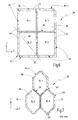
- Fig. 6 shows a plan view of a first composite 80 of exemplarily four module plates 10-1 to 10-4.
- the module plates 10-1 to 10-4 each have, for example, an identical, rectangular basic shape 82-1.
- the module plates 10-1 to 10-4 together define a closed surface 84.
- the closed surface 84 is understood below to mean a surface which covers a substructure (water) tightly.
- the main body 12 of the module plates 10-1 to 10-4 is formed from two rectangular, equally shaped layers 42 which are offset along a diagonal 88 of the basic shape 82-1, as indicated by an arrow 86. To this One obtains the protruding and overhanging edge portions 38 and 40. The position of the connection tabs 22 and the connection receptacles 24 are selected so that they correspond with each other in the connected state.
- the module plates 10 have been wetted with a solution adhesive 92 in order to produce in particular a flat, sealed connection between the individual module plates 10, which is materially bonded.
- the areas of the cohesive connection are in the Fig. 6 hatched shown.
- the protruding edges 38 can be coated with the solution adhesive 92.
- the module plates 10 are brought via the connection tabs 22 and the connection receptacles 24 positively with each other in connection. Then, a slight pressure on the overlapping regions of the module plates 10 can be exerted, so that after a short time forms a cohesive connection at least between the overlapping regions of the module plates 10.
- connection between adjacent module plates 10 does not have to be cohesive. It is sufficient if columns S (cf. Fig. 5 ) are poured between the tops of the module plates 10 with the solution adhesive to achieve a line-shaped cohesive connection between the module plates 10. In the case of Fig. 6 So it is sufficient to pour out or brush on the inside of the adjacent module edges 10 with the solution adhesive.
- Fig. 7 shows a plan view of another composite 80, wherein the module plates 10, of which in the Fig. 7 three pieces are shown, have a hexagonal basic shape 82-2.
- the hexagonal module plates 10-1 to 10-3 of Fig. 7 are preferably multi-layered, here second-layered, constructed.
- the layers 42 are offset from each other by the offset 86 is oriented for example perpendicular to one of the marginal edges, as shown in the Fig. 7 is shown by way of example.
- the Corners 92 'of the hexagonal basic shape 82-2 are thus shifted parallel to the X direction here.
- Adjacent module plates 10 basically fit together in a form-fitting manner and form a closed connection line between them.
- FIG. 12 is a flowchart V1 explaining a method of constructing a (water) dense module plate assembly 80.
- a first module plate 10 is placed on a substructure, such as a roof or a flat roof.
- a further step S12 it is checked whether additional plates are to be laid. If further plates are to be laid, in a further step S14, connecting regions of the (adjacent) module plates 10 to be connected to one another can be wetted with a solution adhesive 92.
- the connection regions are those regions of the module plates 10 which preferably overlap after the mating, ie the connection of the connection lugs 22 and the connection receivers 24, or the alignment with one another (without nose-receiver connections). Usually, these are the protruding and overhanging edge portions 38 and 40.
- connection areas are wetted with the solution adhesive 92 (brushing, spraying, pouring, etc.)
- the module plate 10 to be connected is put on or applied in the connection area, which with the solution adhesive 92 is wetted. It is understood that both module plates 10, which are to be connected to each other, can be wetted with the solution adhesive 92. However, only a single module plate 10 can be wetted with the solution adhesive 92.
- the module plates 10 to be joined together can be aligned and engaged with each other via their connection tabs 22 and their connection receivers 24. However, the solution adhesive 92 can also be applied only after alignment (and, if necessary, bonding). The solution adhesive 92 can be applied several times.
- step S18 one then returns to the query of step S12. If more module plates 10 are to be laid, the steps S14, S16 and S18 are repeated until the entire module plate assembly 80 is constructed. Thereafter, the method V1 ends.
- the substructure can be pre-laid with insulation mats, insulation materials and the like before the module plate assembly 80 is applied to the substructure.
- the module plate composite 80 may itself be attached to the substructure or materials laid underneath.
- the module plate composite 80 can be used in particular for roof renovation. It also serves as a support for PV modules.
- FIG. 9A and 9B a tool and a process is described below, with which one can create from a molding 98, a module plate 10 according to the invention, as exemplified in Fig. 1 is shown.
- Fig. 9A is a joining tool in an open state and in the Fig. 9B shown in a closed state.
- the open state of Fig. 9A is a, preferably warm, molding 98 between a die 94 and a male mold 96 placed so that the molding 98 rests on the die 94.
- the reinforcing strips 36 may be pre-loaded into the die 94 to provide the blank 98 during a subsequent deep drawing operation.
- the thermoforming process is in the Fig. 9A indicated by an arrow 100.
- the arrow 100 indicates that the male 96 is moved from above into the die 94, under a suitable (high) pressure. It is understood that the die and the male are matched with respect to their contours to each other that the die 94 and the male 96 in the closed state of the Fig. 9B leave a cavity between them, which corresponds to the module plate 10 to be produced.
- the module plates 10 are produced according to the manufacturing method V2, they do not bend even after a long storage time and are therefore easy to stack.
- the Fig. 10 shows a flow diagram of a manufacturing method V2, are manufactured with the module plates 10 according to the invention.
- step S30 a (warm) blank 98 is inserted between the die 94 and the male 96.
- the molding 98 is a plastic plate of appropriate thickness.
- step S32 at least one reinforcing strip 36 is previously inserted into the matrix 94, as indicated by a step S32 in FIG Fig. 10 is shown.
- the male 96 is moved downwardly, as shown in FIG Fig. 9A indicated by the arrow 100 to close the thermoforming tool, which consists of the die 94 and the male 96.
- step S36 the finished formed module plate 10 is removed and can subsequently be reworked (cutting, de-grading, etc.), which is shown in the flow chart of FIG Fig. 10 not shown. Subsequently, the process starts from the beginning, as indicated by an arrow S38. Otherwise, the manufacturing process V2 ends.
- domes 26 of adjacent module plates 10 are spaced from each other so that shadow effects adjacent PV modules play no role. This means that shading distances can be taken into account.
- the module plate 10 of the invention is characterized in that it represents only a single component.
- the module plate 10 allows a high degree of pre-assembly. During final assembly, only a few tools are needed. Site technicians can work fast because the module plates 10 are easy to install without having to be complex or calibrated.
- Creating module plate composite systems is easy. It can be covered arbitrarily shaped surfaces. The cover is non-penetrating.
- a module plate composite 80 provides little (additional) ballasting. Nevertheless, PV modules mounted to a substructure with a module plate composite 80 according to the invention are not dug by the wind. Additional weighting or ballasting, e.g. with pebbles, not applicable.
- each module plate 10 is weatherproof.
- Each module plate is preferably made of polyamide (e.g., PA6, PA6.6, and PA6.6 (nylon), PA6.10, etc.).
- PC, PVC, PAx, PMMA, PVDF, PS, PE or PP can be used.
- To make the plastic UV stable e.g. Carbon black are added.
- the plastic is black.
- jamming objects present on the substructure e.g., chimneys, pipes, etc.
- the substructure can be readily recessed by omitting individual module plates 10 from a composite 80.
- the module plate 10 of the invention is recyclable. It allows sufficient ventilation for the PV modules to safely dissipate waste heat.
- the module plate 10 can be used for both framed and frameless PV modules.
- the module plates 10 can be mounted edgewise and / or transversely.
- the domes 26 may be formed at different heights on the same module plate 10 to provide different inclinations in advance.
- a solution adhesive 92 e.g. a water-based adhesive may be used, which may contain a soluble weak acid, e.g. Formic acid.
- the weak acid acts hydrolytically on the OH group of the Moldeküle, that is, H atoms are split off, so that they are reactive again and are used for new crosslinking of the molecules.
- the orientation of the coordinate systems has been based on a north-south orientation (longitudinal direction of the module plate 10) or an east-west orientation (transverse direction of the module plate 10).
Landscapes
- Engineering & Computer Science (AREA)
- Chemical & Material Sciences (AREA)
- Life Sciences & Earth Sciences (AREA)
- Sustainable Development (AREA)
- Sustainable Energy (AREA)
- Thermal Sciences (AREA)
- Physics & Mathematics (AREA)
- Combustion & Propulsion (AREA)
- Mechanical Engineering (AREA)
- General Engineering & Computer Science (AREA)
- Architecture (AREA)
- Civil Engineering (AREA)
- Structural Engineering (AREA)
- Roof Covering Using Slabs Or Stiff Sheets (AREA)
Applications Claiming Priority (1)
| Application Number | Priority Date | Filing Date | Title |
|---|---|---|---|
| DE102011116733.5A DE102011116733B4 (de) | 2011-10-19 | 2011-10-19 | Wasserdichter Modulplattenverbund und Verfahren zum Herstellen eines flächendeckenden Modulplattenverbunds |
Publications (2)
| Publication Number | Publication Date |
|---|---|
| EP2584284A2 true EP2584284A2 (fr) | 2013-04-24 |
| EP2584284A3 EP2584284A3 (fr) | 2013-08-14 |
Family
ID=47044882
Family Applications (1)
| Application Number | Title | Priority Date | Filing Date |
|---|---|---|---|
| EP12188834.1A Withdrawn EP2584284A3 (fr) | 2011-10-19 | 2012-10-17 | Système modulaire de support de module PV, procédé de fabrication d'une plaque de module et procédé de génération d'une enveloppe porteuse étanche de module PV dans le but de l'assainissement de toit |
Country Status (2)
| Country | Link |
|---|---|
| EP (1) | EP2584284A3 (fr) |
| DE (1) | DE102011116733B4 (fr) |
Cited By (3)
| Publication number | Priority date | Publication date | Assignee | Title |
|---|---|---|---|---|
| JP2015115595A (ja) * | 2013-08-09 | 2015-06-22 | エルエス産電株式会社Lsis Co., Ltd. | 太陽光パネル支持体 |
| CN105099355A (zh) * | 2014-05-16 | 2015-11-25 | 杜邦公司 | 用于太阳能电池板的背部安装轨及太阳能电池组件系统 |
| US10505492B2 (en) | 2016-02-12 | 2019-12-10 | Solarcity Corporation | Building integrated photovoltaic roofing assemblies and associated systems and methods |
Citations (3)
| Publication number | Priority date | Publication date | Assignee | Title |
|---|---|---|---|---|
| EP0857926B1 (fr) | 1997-02-06 | 2003-06-04 | Econcern BV | Dispositif pour supporter un panneau solaire et arrangement comprenant ce dispositif |
| EP2040014A2 (fr) | 2007-09-24 | 2009-03-25 | Solarworld Aktiengesellschaft | Structure au sol / à toit plat empilable pour panneaux solaires |
| WO2009077030A1 (fr) | 2007-12-14 | 2009-06-25 | Renusol Gmbh | Support pour un panneau solaire |
Family Cites Families (5)
| Publication number | Priority date | Publication date | Assignee | Title |
|---|---|---|---|---|
| DE2929215C2 (de) | 1979-07-19 | 1983-08-18 | Stiebel Eltron Gmbh & Co Kg, 3450 Holzminden | Rahmen für einen Solarkollektor |
| DE10032011C2 (de) | 2000-07-01 | 2003-02-27 | Gerd Papajewski | Spulenentnahmevorrichtung für eine Doppelsteppstichnähmaschine |
| DE102009019548A1 (de) * | 2009-04-30 | 2010-11-04 | Wilhelm Ötting Kunststoffverformung GmbH & Co. KG | Aufstellmodul und Aufstellsystem für Sonnenkollektoren |
| EP2333450A3 (fr) * | 2009-11-24 | 2012-01-04 | Patrick Perret | Tuile solaire |
| DE102012004128A1 (de) | 2011-03-10 | 2012-09-13 | Creotecc Gmbh | Standardisiertes Befestigungssystem für Photovoltaikmodule und Montageverfahren |
-
2011
- 2011-10-19 DE DE102011116733.5A patent/DE102011116733B4/de not_active Expired - Fee Related
-
2012
- 2012-10-17 EP EP12188834.1A patent/EP2584284A3/fr not_active Withdrawn
Patent Citations (3)
| Publication number | Priority date | Publication date | Assignee | Title |
|---|---|---|---|---|
| EP0857926B1 (fr) | 1997-02-06 | 2003-06-04 | Econcern BV | Dispositif pour supporter un panneau solaire et arrangement comprenant ce dispositif |
| EP2040014A2 (fr) | 2007-09-24 | 2009-03-25 | Solarworld Aktiengesellschaft | Structure au sol / à toit plat empilable pour panneaux solaires |
| WO2009077030A1 (fr) | 2007-12-14 | 2009-06-25 | Renusol Gmbh | Support pour un panneau solaire |
Cited By (3)
| Publication number | Priority date | Publication date | Assignee | Title |
|---|---|---|---|---|
| JP2015115595A (ja) * | 2013-08-09 | 2015-06-22 | エルエス産電株式会社Lsis Co., Ltd. | 太陽光パネル支持体 |
| CN105099355A (zh) * | 2014-05-16 | 2015-11-25 | 杜邦公司 | 用于太阳能电池板的背部安装轨及太阳能电池组件系统 |
| US10505492B2 (en) | 2016-02-12 | 2019-12-10 | Solarcity Corporation | Building integrated photovoltaic roofing assemblies and associated systems and methods |
Also Published As
| Publication number | Publication date |
|---|---|
| DE102011116733A1 (de) | 2013-04-25 |
| EP2584284A3 (fr) | 2013-08-14 |
| DE102011116733B4 (de) | 2014-08-21 |
Similar Documents
| Publication | Publication Date | Title |
|---|---|---|
| EP1833098A1 (fr) | Support pour panneau solaire à base de plastique | |
| DE202008014174U1 (de) | Träger für ein Solarpaneel | |
| DE102013006332A1 (de) | Solarmodulträger für die Belegung von schrägen Objektflächen mit homogener Flächenbedeckung | |
| EP0041724A1 (fr) | Plaque traversée par un fluide | |
| DE102007041199A1 (de) | Solareinrichtung | |
| EP2060217B1 (fr) | Structure de cuvette de douche et procédé de montage d'une structure de cuvette de douche | |
| DE3712867A1 (de) | Wasserfangschale | |
| WO2009124409A2 (fr) | Système pour produire du courant solaire | |
| DE102011116733B4 (de) | Wasserdichter Modulplattenverbund und Verfahren zum Herstellen eines flächendeckenden Modulplattenverbunds | |
| DE3337658A1 (de) | Grossflaechige solarplatte mit halbleiterphotoelementen | |
| DE102006061284A1 (de) | Plattenförmiges photovoltaisches Solarmodul mit Rahmen aus Formprofilen | |
| DE102016118031A1 (de) | Duschanordnung sowie Verfahren zur Herstellung und Montage der Duschanordnung | |
| DE202010005385U1 (de) | Ständer eines Solarmoduls | |
| DE202018006501U1 (de) | Dichtungskragen zur Verwendung beim Einbauen eines Fensterrahmens in einer geneigten Dachstruktur | |
| WO2001069689A1 (fr) | Element a energie avec couche photovoltaique | |
| DE102006006718B4 (de) | Solarkollektor | |
| DE102011122340A1 (de) | Photovoltaikanlage und ein Verfahren zur Herstellung einer Photovoltaikanlage | |
| DE60009107T2 (de) | Plattenförmiges bauelement | |
| EP0339537B1 (fr) | Plancher creux | |
| EP0018543A1 (fr) | Collecteur d'énergie solaire | |
| DE19756634A1 (de) | Plattenteil bzw. Wandteil für Gebäude, Böden oder Schwimmbadanlagen | |
| EP2476971B1 (fr) | Collecteur Solaire | |
| DE102009016072A1 (de) | Vorrichtung zum Anordnen von Solarmodulen | |
| WO2018024801A1 (fr) | Module photovoltaïque, procédé de réalisation d'un module photovoltaïque, montant profilé pour un cadre profilé, cadre profilé et système photovoltaïque | |
| DE19727922A1 (de) | Rohrfixiervorrichtung für Flächenheizungsrohre, insbesondere Fußbodenheizungsrohre |
Legal Events
| Date | Code | Title | Description |
|---|---|---|---|
| PUAI | Public reference made under article 153(3) epc to a published international application that has entered the european phase |
Free format text: ORIGINAL CODE: 0009012 |
|
| AK | Designated contracting states |
Kind code of ref document: A2 Designated state(s): AL AT BE BG CH CY CZ DE DK EE ES FI FR GB GR HR HU IE IS IT LI LT LU LV MC MK MT NL NO PL PT RO RS SE SI SK SM TR |
|
| AX | Request for extension of the european patent |
Extension state: BA ME |
|
| PUAL | Search report despatched |
Free format text: ORIGINAL CODE: 0009013 |
|
| AK | Designated contracting states |
Kind code of ref document: A3 Designated state(s): AL AT BE BG CH CY CZ DE DK EE ES FI FR GB GR HR HU IE IS IT LI LT LU LV MC MK MT NL NO PL PT RO RS SE SI SK SM TR |
|
| AX | Request for extension of the european patent |
Extension state: BA ME |
|
| RIC1 | Information provided on ipc code assigned before grant |
Ipc: F24J 2/46 20060101ALI20130711BHEP Ipc: F24J 2/04 20060101ALI20130711BHEP Ipc: H01L 31/048 20060101ALI20130711BHEP Ipc: H01L 31/042 20060101ALI20130711BHEP Ipc: F24J 2/00 20060101ALI20130711BHEP Ipc: F24J 2/52 20060101AFI20130711BHEP |
|
| 17P | Request for examination filed |
Effective date: 20140213 |
|
| RBV | Designated contracting states (corrected) |
Designated state(s): AL AT BE BG CH CY CZ DE DK EE ES FI FR GB GR HR HU IE IS IT LI LT LU LV MC MK MT NL NO PL PT RO RS SE SI SK SM TR |
|
| RAP1 | Party data changed (applicant data changed or rights of an application transferred) |
Owner name: CREOTECC GMBH |
|
| STAA | Information on the status of an ep patent application or granted ep patent |
Free format text: STATUS: THE APPLICATION IS DEEMED TO BE WITHDRAWN |
|
| 18D | Application deemed to be withdrawn |
Effective date: 20160503 |