EP2584300A1 - Dispositif de refroidissement pour une turbine à vapeur - Google Patents
Dispositif de refroidissement pour une turbine à vapeur Download PDFInfo
- Publication number
- EP2584300A1 EP2584300A1 EP12006420.9A EP12006420A EP2584300A1 EP 2584300 A1 EP2584300 A1 EP 2584300A1 EP 12006420 A EP12006420 A EP 12006420A EP 2584300 A1 EP2584300 A1 EP 2584300A1
- Authority
- EP
- European Patent Office
- Prior art keywords
- cooling
- water
- condensate
- container
- cooling device
- Prior art date
- Legal status (The legal status is an assumption and is not a legal conclusion. Google has not performed a legal analysis and makes no representation as to the accuracy of the status listed.)
- Withdrawn
Links
- 238000001816 cooling Methods 0.000 title claims abstract description 94
- 239000000498 cooling water Substances 0.000 claims abstract description 41
- XLYOFNOQVPJJNP-UHFFFAOYSA-N water Substances O XLYOFNOQVPJJNP-UHFFFAOYSA-N 0.000 claims abstract description 37
- 238000000034 method Methods 0.000 claims abstract description 11
- 230000005484 gravity Effects 0.000 claims abstract description 6
- 238000009434 installation Methods 0.000 claims description 4
- 239000012809 cooling fluid Substances 0.000 claims description 2
- 238000011144 upstream manufacturing Methods 0.000 claims description 2
- 238000007599 discharging Methods 0.000 abstract 2
- 239000003570 air Substances 0.000 description 11
- 238000005381 potential energy Methods 0.000 description 7
- 239000012080 ambient air Substances 0.000 description 3
- 101150038956 cup-4 gene Proteins 0.000 description 3
- 239000007788 liquid Substances 0.000 description 3
- 238000011084 recovery Methods 0.000 description 3
- 239000002352 surface water Substances 0.000 description 3
- 239000003990 capacitor Substances 0.000 description 2
- 238000010276 construction Methods 0.000 description 2
- 238000007872 degassing Methods 0.000 description 2
- 241000736911 Turritella communis Species 0.000 description 1
- 230000001154 acute effect Effects 0.000 description 1
- 230000002411 adverse Effects 0.000 description 1
- 239000002826 coolant Substances 0.000 description 1
- 238000009792 diffusion process Methods 0.000 description 1
- 239000000428 dust Substances 0.000 description 1
- 230000000694 effects Effects 0.000 description 1
- 238000001704 evaporation Methods 0.000 description 1
- 230000008020 evaporation Effects 0.000 description 1
- 230000002349 favourable effect Effects 0.000 description 1
- 230000002262 irrigation Effects 0.000 description 1
- 238000003973 irrigation Methods 0.000 description 1
- 230000000704 physical effect Effects 0.000 description 1
Images


Classifications
-
- F—MECHANICAL ENGINEERING; LIGHTING; HEATING; WEAPONS; BLASTING
- F28—HEAT EXCHANGE IN GENERAL
- F28C—HEAT-EXCHANGE APPARATUS, NOT PROVIDED FOR IN ANOTHER SUBCLASS, IN WHICH THE HEAT-EXCHANGE MEDIA COME INTO DIRECT CONTACT WITHOUT CHEMICAL INTERACTION
- F28C1/00—Direct-contact trickle coolers, e.g. cooling towers
-
- F—MECHANICAL ENGINEERING; LIGHTING; HEATING; WEAPONS; BLASTING
- F01—MACHINES OR ENGINES IN GENERAL; ENGINE PLANTS IN GENERAL; STEAM ENGINES
- F01K—STEAM ENGINE PLANTS; STEAM ACCUMULATORS; ENGINE PLANTS NOT OTHERWISE PROVIDED FOR; ENGINES USING SPECIAL WORKING FLUIDS OR CYCLES
- F01K9/00—Plants characterised by condensers arranged or modified to co-operate with the engines
- F01K9/003—Plants characterised by condensers arranged or modified to co-operate with the engines condenser cooling circuits
-
- F—MECHANICAL ENGINEERING; LIGHTING; HEATING; WEAPONS; BLASTING
- F28—HEAT EXCHANGE IN GENERAL
- F28B—STEAM OR VAPOUR CONDENSERS
- F28B1/00—Condensers in which the steam or vapour is separate from the cooling medium by walls, e.g. surface condenser
- F28B1/06—Condensers in which the steam or vapour is separate from the cooling medium by walls, e.g. surface condenser using air or other gas as the cooling medium
-
- F—MECHANICAL ENGINEERING; LIGHTING; HEATING; WEAPONS; BLASTING
- F28—HEAT EXCHANGE IN GENERAL
- F28B—STEAM OR VAPOUR CONDENSERS
- F28B9/00—Auxiliary systems, arrangements, or devices
- F28B9/08—Auxiliary systems, arrangements, or devices for collecting and removing condensate
-
- F—MECHANICAL ENGINEERING; LIGHTING; HEATING; WEAPONS; BLASTING
- F28—HEAT EXCHANGE IN GENERAL
- F28F—DETAILS OF HEAT-EXCHANGE AND HEAT-TRANSFER APPARATUS, OF GENERAL APPLICATION
- F28F25/00—Component parts of trickle coolers
- F28F25/02—Component parts of trickle coolers for distributing, circulating, and accumulating liquid
-
- F—MECHANICAL ENGINEERING; LIGHTING; HEATING; WEAPONS; BLASTING
- F28—HEAT EXCHANGE IN GENERAL
- F28F—DETAILS OF HEAT-EXCHANGE AND HEAT-TRANSFER APPARATUS, OF GENERAL APPLICATION
- F28F27/00—Control arrangements or safety devices specially adapted for heat-exchange or heat-transfer apparatus
- F28F27/003—Control arrangements or safety devices specially adapted for heat-exchange or heat-transfer apparatus specially adapted for cooling towers
-
- F—MECHANICAL ENGINEERING; LIGHTING; HEATING; WEAPONS; BLASTING
- F28—HEAT EXCHANGE IN GENERAL
- F28F—DETAILS OF HEAT-EXCHANGE AND HEAT-TRANSFER APPARATUS, OF GENERAL APPLICATION
- F28F25/00—Component parts of trickle coolers
- F28F2025/005—Liquid collection; Liquid treatment; Liquid recirculation; Addition of make-up liquid
-
- F—MECHANICAL ENGINEERING; LIGHTING; HEATING; WEAPONS; BLASTING
- F28—HEAT EXCHANGE IN GENERAL
- F28F—DETAILS OF HEAT-EXCHANGE AND HEAT-TRANSFER APPARATUS, OF GENERAL APPLICATION
- F28F25/00—Component parts of trickle coolers
- F28F25/02—Component parts of trickle coolers for distributing, circulating, and accumulating liquid
- F28F25/04—Distributing or accumulator troughs
-
- Y—GENERAL TAGGING OF NEW TECHNOLOGICAL DEVELOPMENTS; GENERAL TAGGING OF CROSS-SECTIONAL TECHNOLOGIES SPANNING OVER SEVERAL SECTIONS OF THE IPC; TECHNICAL SUBJECTS COVERED BY FORMER USPC CROSS-REFERENCE ART COLLECTIONS [XRACs] AND DIGESTS
- Y02—TECHNOLOGIES OR APPLICATIONS FOR MITIGATION OR ADAPTATION AGAINST CLIMATE CHANGE
- Y02B—CLIMATE CHANGE MITIGATION TECHNOLOGIES RELATED TO BUILDINGS, e.g. HOUSING, HOUSE APPLIANCES OR RELATED END-USER APPLICATIONS
- Y02B30/00—Energy efficient heating, ventilation or air conditioning [HVAC]
- Y02B30/70—Efficient control or regulation technologies, e.g. for control of refrigerant flow, motor or heating
Definitions
- the invention relates to a cooling device for a steam turbine power plant, for example in the form of a wet cooling tower or an air condenser.
- the invention is also applicable to other cooling devices such as hybrid and dry cooling towers.
- the invention further relates to a method for cooling condensate or cooling water of a steam turbine process using a cooling device in the form of a wet cooling tower or an air condenser.
- the exhaust steam from the steam turbine is usually recondensed by means of a condenser, wherein the recondensation can be operated, for example, by means of an air condenser.
- capacitors are operated with water as the cooling medium, wherein the cooling water is cooled in cooling towers.
- cooling towers are often designed as so-called wet cooling towers. In these, the cooling water is trickled with partial evaporation and either recycled in the circuit to the condenser or introduced into a surface water.
- cooling water trickled down in cooling towers contains considerable amounts of potential energy, which remains essentially unused in conventional systems.
- a method for operating a cooling device for steam power plants with a wet cooling tower in which the cooling water is fed to a riser shaft, with distribution channels fed by the riser shaft for trickling the cooling water, with shut-off devices for the distribution channels and with an overflow shaft for receiving excess cooling water, wherein the power outlet of the cooling water permanently takes place in the water outlet of the cooling tower riser shaft and the raid shaft is so designed in that it can discharge the entire cooling water flow, with the entire flow of cooling water flowing through the chute when the distribution channels are closed.
- the invention is therefore an object of the invention to improve a cooling device for a steam turbine power plant with at least one means for draining condensate and / or cooling water in terms of the use of the potential energy of the condensate or cooling water, in particular to provide such an arrangement, which is structurally easier to implement ,
- the invention has for its object to provide a corresponding method for recovering potential energy of the cooling water.
- a cooling device for a steam turbine power plant with at least one device for draining condensate or cooling water under gravity, with at least one collector for condensate and / or cooling water, wherein the collecting device is designed as a rotary container or the collecting device, a rotary container in the form of a At least gravitational water vortex is generated in the rotation container with running condensate or cooling water, and wherein within the rotation container or in a drain of the rotation container at least one water turbine is arranged, with which the rotational energy of the condensate or cooling water is converted into electrical energy.
- the cooling device according to the invention has the advantage, in particular in the case of energy recovery from the condensate, that due to the imposition of a rotational flow / tangential flow on the condensate, improved degassing of the condensate is effected.
- the rotation increases the residence time of the water in the collector so that better cooling is achieved.
- cooling device Another advantage of the cooling device according to the invention is that water vortex turbines are usable, which are operable at low speeds and high torques. Over a relatively small geodetic height difference, a relatively large rotational moment can be generated. As a result, savings in height for the cooling device are possible.
- both an open rotation basin and a Tos tube with an approximately tangential flow guidance to be understood.
- the rotary container according to the invention is expediently flowed tangentially, so that a gravitational vortex is formed therein, which forms a conical vortex approximately in the axis of symmetry of the rotary container.
- An advantageous embodiment of the cooling device according to the invention is an embodiment as a wet cooling tower with at least one provided below Verrieselungseinbauten rotation container and an associated water turbine.
- the wet cooling tower has a cooling tower cup, which is formed overall as a rotary container or as a rotary basin.
- a water vortex turbine may be arranged in the center of the rotary tank or in an outlet of the rotary tank.
- this may have an approximately vertically extending rotor / rotor with approximately radial blading, which is tangentially flowed through by the adjusting in the rotary basin Gravitationswasserwirbel.
- An approximately cylindrical turbine, which is arranged in the center of the rotary tank, thus requires only a relatively small amount to be bridged by the liquid to be able to be operated with relatively high torque.
- cooling device in an expedient and advantageous embodiment, it is provided that a plurality of, preferably cascaded, collecting devices are provided below the sprinkling installations, which feed one or more rotary containers.
- This construction is simple to retrofit and requires no complex design changes known cooling devices.
- funnels may be provided as collecting devices, which are arranged in a step-like manner, for example, falling from the symmetry axis of the cooling tower in the direction radially outward at different levels.
- the smallest amount of surface area / projection surface of the cooling tower can absorb the entire amount of water that has been trickled off and make full use of its potential energy.
- At least one rotary container is connected downstream of a cooling water collecting container at the level of the cooling tower cup or below this level.
- a reservoir / power pool can be provided, which feeds a rotating pool tangentially.
- Another cooling device is designed as an air condenser, wherein this cooling device is characterized in that at least one rotary container and at least one water turbine are connected upstream of a condensate collecting tank.
- the rotary container may be formed as opening into the condensate collecting Tos tube, which is provided, for example, with appropriate flow installations for enforcing a tangential flow / vortex flow.
- the object underlying the invention is further achieved by a method for cooling condensate or cooling water of a
- a steam turbine process using a cooling device in the form of a wet cooling tower or an air condenser in which condensate or cooling fluid is applied by utilizing a geodetic height difference of a turbulent flow and the turbulent flow is converted into electric power using at least one water vortex turbine, preferably with a substantially vertically arranged impeller.
- the generation of a gravitational vortex or the generation of a rotational flow in a rotary basin has the physical effect that warmer and lighter water in the flow radially enriches the outside, cold and denser water, however, accumulates near the center of the gravitational water vortex and thus dissipates faster, thereby a more favorable temperature profile and a higher residence time for warmer condensate or warmer cooling water results.
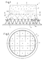
- a cooling device for a steam turbine power plant is in the Figures 1-4 shown.
- the cooling device is designed as a wet cooling tower 1 known per se.
- the wet cooling tower 1 is formed in a known manner with an elevated cooling tower shell 2 in the form of a bivalve hyperboloid.
- Above the Rieseleinbauten 3 means for atomizing the cooling water are provided.
- the cooling water is trickled in countercurrent to an ambient air flow, which rises between a cooling tower cup 4 and the shell 2 through the wet cooling tower 1.
- the wet cooling tower 1 according to the described embodiment is designed as Naturzugkühlturm, that is, the flow of ambient air is carried out substantially without fan assistance.
- a plurality of funnels 5 are arranged, which collect the trickled cooling water and each introduce tangentially into a rotary tank 6.
- several rotary tanks 6 are placed on the bottom of the cooling tower cup 4, which are each fed by a plurality of funnels 5 with cooling water.
- the funnel 5 can be arranged close to each other under the Rieseleinbauten 3 close together.
- the funnels 5 may also be arranged in an overlapping cascading manner.
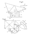
- the funnels 5, as in FIG. 4 is hinted, viewed from the axis of rotation of the wet cooling tower 1 from the edge towards different height levels, that are arranged sloping. Since the funnels 5 basically constitute a flow obstacle for the natural draft of the wet cooling tower 1, at least the funnels 5 arranged at the edge of the cooling tower cup 4 are at least partially covered and / or lined with a baffle 8 in such a way that the ambient air draft enters the interior of the wet cooling tower 1 through the framework 7 is guided through.
- the incoming air can be streamlined streamlined in the trickle surfaces. This flow control optimizes the admission of the trickle surfaces and reduces the flow losses.
- Each of the funnels 5 is provided with an outlet 9, which is connected tangentially to a rotary tank 6, in each of which an approximately vertically extending impeller 10 of a water vortex turbine 20 is arranged.
- the impeller 10 is provided with radially extending blades 11, which are driven by a gravity water vortex, which adjusts itself in the rotary tank 6, and which drive the rotor, not shown, of a generator.
- the impeller 10 of the water vortex turbine 20 is arranged longitudinally within the rotation bowl 6.
- the usable geodetic height difference for generating the gravitational vortex results from the upper edge of the liquid level in a funnel 5 to approximately the upper edge of the liquid level in the rotary basin 6.
- FIG. 5 Another variant of the cooling device according to the invention is shown in FIG FIG. 5 shown.
- the cooling device according to this embodiment is designed as a per se known air capacitor 12.
- the air condenser 12 comprises roof-shaped elevated cooling tubes 13, each extending on both sides of a vapor line 14 at an acute angle to each other downwards, thus forming a kind gable roof structure.
- the cooling tubes 13 are in turn elevated on a stator frame 7 and forcibly ventilated from below by means of fans 15.
- the exhaust steam is distributed via the exhaust steam line 14 to the cooling tubes 13, in which condensate forms as a result, which is guided by gravity in the tube bundles to a manifold 16.
- the Manifold 16 enters the condensate in a designed as a rotary container Tos-tube 17, in which the manifold 16 opens tangentially.
- Tos-tube 17 helical flow baffles 18 are provided, below which an inlet funnel 19 is arranged for a water vortex turbine 20.
- the water vortex turbine 20 may comprise a substantially cylindrical, vertically disposed rotor with radially extending blades.
- a tangential flow is generated which converts the potential energy of the water into a rotational flow or into a gravitational vortex via the available geodetic height from the manifold 16 up to the level of the inlet funnel 19 within the Tos tube 17 driving the hydro-vortex turbine 20.
- the water vortex turbine 20 or the Tos tube 17 is connected to a horizontal condensate collection tank 21, the in FIG. 6 only hinted at.
- the Tos tube can be integrated into the condensate collector.
- the condensate collecting container can be arranged standing in the case. The upright construction is statically cheaper and saves system area. The provision of large degassing surfaces of the condensate takes place in the film outlet in the Tos tube.
Landscapes
- Engineering & Computer Science (AREA)
- Mechanical Engineering (AREA)
- General Engineering & Computer Science (AREA)
- Physics & Mathematics (AREA)
- Thermal Sciences (AREA)
- Chemical & Material Sciences (AREA)
- Combustion & Propulsion (AREA)
- Engine Equipment That Uses Special Cycles (AREA)
Applications Claiming Priority (1)
| Application Number | Priority Date | Filing Date | Title |
|---|---|---|---|
| DE102011116078A DE102011116078A1 (de) | 2011-10-18 | 2011-10-18 | Kühlvorrichtung für ein Dampfturbinenkraftwerk |
Publications (1)
| Publication Number | Publication Date |
|---|---|
| EP2584300A1 true EP2584300A1 (fr) | 2013-04-24 |
Family
ID=46939452
Family Applications (1)
| Application Number | Title | Priority Date | Filing Date |
|---|---|---|---|
| EP12006420.9A Withdrawn EP2584300A1 (fr) | 2011-10-18 | 2012-09-13 | Dispositif de refroidissement pour une turbine à vapeur |
Country Status (2)
| Country | Link |
|---|---|
| EP (1) | EP2584300A1 (fr) |
| DE (1) | DE102011116078A1 (fr) |
Cited By (1)
| Publication number | Priority date | Publication date | Assignee | Title |
|---|---|---|---|---|
| CN103615399A (zh) * | 2013-11-14 | 2014-03-05 | 芜湖凯博尔高科实业有限公司 | 一种水汽混合动力装置 |
Families Citing this family (1)
| Publication number | Priority date | Publication date | Assignee | Title |
|---|---|---|---|---|
| DE102021005770A1 (de) | 2021-11-22 | 2023-05-25 | Serge Olivier Menkuimb | Neuartiges und regeneratives Energieerzeugungskühlsystem |
Citations (10)
| Publication number | Priority date | Publication date | Assignee | Title |
|---|---|---|---|---|
| DE295922C (fr) * | ||||
| DE1111220B (de) * | 1956-11-19 | 1961-07-20 | Kraftanlagen Ag | Rueckkuehlturm |
| US3372905A (en) * | 1967-07-20 | 1968-03-12 | Kenard D. Brown | Power generating method and apparatus |
| US4076448A (en) * | 1975-08-21 | 1978-02-28 | Sanders Jr Davis A | Power generating water turbine |
| US4187686A (en) * | 1978-01-16 | 1980-02-12 | Pommier Lorenzo A | Power generator utilizing elevation-temperature differential |
| US4391100A (en) * | 1979-08-27 | 1983-07-05 | Smith Derrick A | Closed loop hermetically sealed solar power generator |
| US5921745A (en) * | 1997-09-29 | 1999-07-13 | Hydroenergy Corporation | Low head turbine |
| AT412363B (de) * | 2003-01-03 | 2005-01-25 | Franz Dipl Ing Zotloeterer | Wasserkraftwerk |
| GB2439832A (en) * | 2006-07-01 | 2008-01-09 | Donald Green | Turbine in power station cooling tower outlet |
| DE102007036343B4 (de) | 2007-08-02 | 2009-12-31 | Enbw Kraftwerke Ag | Verfahren und Kühlvorrichtung für Dampfkraftwerke mit einem Nasskühlturm |
Family Cites Families (3)
| Publication number | Priority date | Publication date | Assignee | Title |
|---|---|---|---|---|
| US2151949A (en) * | 1934-07-30 | 1939-03-28 | Edward T Turner | Method and apparatus for converting heat energy into mechanical energy |
| US2265878A (en) * | 1938-10-20 | 1941-12-09 | Walter S Stoker | Power apparatus |
| WO2003095802A1 (fr) * | 2002-05-14 | 2003-11-20 | Efthimios Angelopoulos | Centrale combinant dessalement et production hydroelectrique |
-
2011
- 2011-10-18 DE DE102011116078A patent/DE102011116078A1/de not_active Withdrawn
-
2012
- 2012-09-13 EP EP12006420.9A patent/EP2584300A1/fr not_active Withdrawn
Patent Citations (10)
| Publication number | Priority date | Publication date | Assignee | Title |
|---|---|---|---|---|
| DE295922C (fr) * | ||||
| DE1111220B (de) * | 1956-11-19 | 1961-07-20 | Kraftanlagen Ag | Rueckkuehlturm |
| US3372905A (en) * | 1967-07-20 | 1968-03-12 | Kenard D. Brown | Power generating method and apparatus |
| US4076448A (en) * | 1975-08-21 | 1978-02-28 | Sanders Jr Davis A | Power generating water turbine |
| US4187686A (en) * | 1978-01-16 | 1980-02-12 | Pommier Lorenzo A | Power generator utilizing elevation-temperature differential |
| US4391100A (en) * | 1979-08-27 | 1983-07-05 | Smith Derrick A | Closed loop hermetically sealed solar power generator |
| US5921745A (en) * | 1997-09-29 | 1999-07-13 | Hydroenergy Corporation | Low head turbine |
| AT412363B (de) * | 2003-01-03 | 2005-01-25 | Franz Dipl Ing Zotloeterer | Wasserkraftwerk |
| GB2439832A (en) * | 2006-07-01 | 2008-01-09 | Donald Green | Turbine in power station cooling tower outlet |
| DE102007036343B4 (de) | 2007-08-02 | 2009-12-31 | Enbw Kraftwerke Ag | Verfahren und Kühlvorrichtung für Dampfkraftwerke mit einem Nasskühlturm |
Cited By (2)
| Publication number | Priority date | Publication date | Assignee | Title |
|---|---|---|---|---|
| CN103615399A (zh) * | 2013-11-14 | 2014-03-05 | 芜湖凯博尔高科实业有限公司 | 一种水汽混合动力装置 |
| CN103615399B (zh) * | 2013-11-14 | 2016-05-25 | 芜湖凯博尔高科实业有限公司 | 一种水汽混合动力装置 |
Also Published As
| Publication number | Publication date |
|---|---|
| DE102011116078A1 (de) | 2013-04-18 |
Similar Documents
| Publication | Publication Date | Title |
|---|---|---|
| US2732190A (en) | Cross flow cooling tower having recycling system | |
| DE3107695A1 (de) | Stromerzeugungsanlage | |
| CN205604335U (zh) | 一种用于园林灌溉的雨水收集装置 | |
| DE2430475A1 (de) | Verfahren und kuehlturm zum abfuehren von abwaerme | |
| DE102009016643B4 (de) | Rohr und Leitelement zum Einbau in ein Rohr | |
| DE102007036343B4 (de) | Verfahren und Kühlvorrichtung für Dampfkraftwerke mit einem Nasskühlturm | |
| DE112011101248T5 (de) | Gerät zur Abscheidung von Wasser im Vakuumsystem einer Papiermaschine und Verfahren zu seiner Verwendung | |
| DE2648318A1 (de) | Wasserkraftwerk | |
| DE102011116078A1 (de) | Kühlvorrichtung für ein Dampfturbinenkraftwerk | |
| DE2353111C3 (de) | Einrichtung zum Abscheiden von Wasser aus Dampf-Wasser-Gemischen | |
| CN105804949B (zh) | 塔式卧叶液压储能风力发电机 | |
| DE10351198A1 (de) | Meerwasserentsalzungsverfahren | |
| AT510573B1 (de) | Windkraftanlage | |
| WO2012048680A1 (fr) | Tube et élément conducteur à incorporer dans un tube | |
| AT510280B1 (de) | Windkraftanlage | |
| EP0344094B1 (fr) | Réservoir de détente pour fluides chauds sous pression | |
| DE4441749A1 (de) | Vorrichtung zum In-Kontakt-Bringen einer Flüssigkeit mit einem Gas | |
| DE202008014037U1 (de) | Autonomes, unabhängig von äußeren Energiequellen arbeitendes Wasserkraftwerk | |
| CN214936225U (zh) | 一种管道式油气水分离与污水处理装置 | |
| DE102013106329B4 (de) | Verfahren und Anordnung zum Evakuieren eines Rohrleitungssystems | |
| DE102014018168A1 (de) | Rohrströmungskraftwerk | |
| EP2715106B1 (fr) | Turbine pelton à tubulure d'aspiration | |
| DE10335961B4 (de) | Vorrichtung und Verfahren zur anaeroben Reinigung von Abwasser | |
| CN206081754U (zh) | 一种塔板液相中漂浮物的采集器 | |
| CN209161557U (zh) | 泵后油水渣分离器 |
Legal Events
| Date | Code | Title | Description |
|---|---|---|---|
| PUAI | Public reference made under article 153(3) epc to a published international application that has entered the european phase |
Free format text: ORIGINAL CODE: 0009012 |
|
| AK | Designated contracting states |
Kind code of ref document: A1 Designated state(s): AL AT BE BG CH CY CZ DE DK EE ES FI FR GB GR HR HU IE IS IT LI LT LU LV MC MK MT NL NO PL PT RO RS SE SI SK SM TR |
|
| AX | Request for extension of the european patent |
Extension state: BA ME |
|
| 17P | Request for examination filed |
Effective date: 20131017 |
|
| RBV | Designated contracting states (corrected) |
Designated state(s): AL AT BE BG CH CY CZ DE DK EE ES FI FR GB GR HR HU IE IS IT LI LT LU LV MC MK MT NL NO PL PT RO RS SE SI SK SM TR |
|
| STAA | Information on the status of an ep patent application or granted ep patent |
Free format text: STATUS: THE APPLICATION IS DEEMED TO BE WITHDRAWN |
|
| 18D | Application deemed to be withdrawn |
Effective date: 20150401 |