EP2584329A1 - Vorrichtung zum Testen eines Sensors für Zugunterwagentemperaturen - Google Patents
Vorrichtung zum Testen eines Sensors für Zugunterwagentemperaturen Download PDFInfo
- Publication number
- EP2584329A1 EP2584329A1 EP11185451.9A EP11185451A EP2584329A1 EP 2584329 A1 EP2584329 A1 EP 2584329A1 EP 11185451 A EP11185451 A EP 11185451A EP 2584329 A1 EP2584329 A1 EP 2584329A1
- Authority
- EP
- European Patent Office
- Prior art keywords
- sensor
- heat
- heat emitter
- emissions
- test apparatus
- Prior art date
- Legal status (The legal status is an assumption and is not a legal conclusion. Google has not performed a legal analysis and makes no representation as to the accuracy of the status listed.)
- Ceased
Links
Images


Classifications
-
- B—PERFORMING OPERATIONS; TRANSPORTING
- B61—RAILWAYS
- B61K—AUXILIARY EQUIPMENT SPECIALLY ADAPTED FOR RAILWAYS, NOT OTHERWISE PROVIDED FOR
- B61K9/00—Railway vehicle profile gauges; Detecting or indicating overheating of components; Apparatus on locomotives or cars to indicate bad track sections; General design of track recording vehicles
- B61K9/04—Detectors for indicating the overheating of axle bearings and the like, e.g. associated with the brake system for applying the brakes in case of a fault
- B61K9/06—Detectors for indicating the overheating of axle bearings and the like, e.g. associated with the brake system for applying the brakes in case of a fault by detecting or indicating heat radiation from overheated axles
-
- G—PHYSICS
- G01—MEASURING; TESTING
- G01J—MEASUREMENT OF INTENSITY, VELOCITY, SPECTRAL CONTENT, POLARISATION, PHASE OR PULSE CHARACTERISTICS OF INFRARED, VISIBLE OR ULTRAVIOLET LIGHT; COLORIMETRY; RADIATION PYROMETRY
- G01J5/00—Radiation pyrometry, e.g. infrared or optical thermometry
- G01J5/02—Constructional details
-
- G—PHYSICS
- G01—MEASURING; TESTING
- G01J—MEASUREMENT OF INTENSITY, VELOCITY, SPECTRAL CONTENT, POLARISATION, PHASE OR PULSE CHARACTERISTICS OF INFRARED, VISIBLE OR ULTRAVIOLET LIGHT; COLORIMETRY; RADIATION PYROMETRY
- G01J5/00—Radiation pyrometry, e.g. infrared or optical thermometry
- G01J5/52—Radiation pyrometry, e.g. infrared or optical thermometry using comparison with reference sources, e.g. disappearing-filament pyrometer
- G01J5/53—Reference sources, e.g. standard lamps; Black bodies
-
- G—PHYSICS
- G01—MEASURING; TESTING
- G01J—MEASUREMENT OF INTENSITY, VELOCITY, SPECTRAL CONTENT, POLARISATION, PHASE OR PULSE CHARACTERISTICS OF INFRARED, VISIBLE OR ULTRAVIOLET LIGHT; COLORIMETRY; RADIATION PYROMETRY
- G01J5/00—Radiation pyrometry, e.g. infrared or optical thermometry
- G01J5/52—Radiation pyrometry, e.g. infrared or optical thermometry using comparison with reference sources, e.g. disappearing-filament pyrometer
- G01J5/53—Reference sources, e.g. standard lamps; Black bodies
- G01J5/532—Reference sources, e.g. standard lamps; Black bodies using a reference heater of the emissive surface type, e.g. for selectively absorbing materials
Definitions
- This disclosure generally relates to the field of rail transportation, and to the field of infrared sensors for undercarriage components of trains. This disclosure relates, more particularly, to the testing of infrared sensors for undercarriage components of trains.
- Safe and reliable operation of a railroad system may be dependent upon the integrity of the undercarriage components of the vehicles travelling over the rails.
- Worn or damaged train wheel bearings may increase the rolling friction of an axle requiring an increase of power to move the train.
- worn or damaged bearings may cause excessive wear to the train axle and, in the case of failure of the bearing, may even cause the axle to lock up, preventing rotation of the wheel and thus resulting in a potential fire hazard due to the heat build up and potential sparking caused by friction of the locked wheel scraping along the rail.
- Bearing temperatures may be scanned by sensing a temperature of the wheel bearing indirectly through a bearing box surrounding the wheel bearing on a rail car of a train.
- IR infrared radiation
- sensors may be mounted along a rail to detect IR energy emitted by an outer wheel bearing of passing rail cars. The emissions of IR energy may be indicative of a temperature of the wheel bearing.
- the bearing temperatures may be scanned by sensors that may comprise sensing elements which may be aimed at different parts of a target scanning area of a rail vehicle undercarriage component.
- the IR data obtained may be used to generate respective scanning signature waveform data corresponding to each different region.
- the sensor may be oriented so that at least one of the elements receives unobstructed infrared emissions from the undercarriage component of a rail vehicle passing the sensor.
- a control circuit for the sensors may cause an alarm to be raised if the IR data is indicative of temperature that is higher than a pre-set temperature threshold.
- the sensors may have failures in performance which may not be detectable by the sensors or by the control circuit connected to the sensors.
- a failure may be the misalignment in a sensing element such that the element is no longer aimed at a target area of a rail vehicle undercarriage component.
- Another failure may be an incorrect data being generated based on the IR emissions.
- the present disclosure is directed, at least in part, to improving or overcoming one or more aspects of the prior art system.
- the present disclosure describes a test apparatus for a IR sensor of a rail vehicle undercarriage component, the test apparatus comprising a heat emitter for producing IR emissions at a reference temperature; a support for supporting the heat emitter at a position spaced from the passage of the rail vehicle and in an orientation for directing the IR emissions at the IR sensor.
- the present disclosure describes a method of testing an IR sensor of a rail vehicle undercarriage component, the method comprising the steps of providing a heat emitter for producing IR emissions at a reference temperature; supporting the heat emitter on a support at a position spaced from the passage of the rail vehicle and in an orientation for directing the IR emissions at the IR sensor; activating the heat emitter to produce IR emissions at the reference temperature; and comparing the reference temperature and the temperature detected by the IR sensor.
- the test apparatus 10 may test the accuracy and reliability of the an IR sensor 36 .
- the test apparatus 10 may be located at a rail track 30 for testing the IR sensor 36 that may be positioned in a rail bed of the track 30 , such as within a cross tie or a sleeper 34 .
- the IR sensor 36 may obtain IR data from a rail vehicle undercarriage 40 .
- the rail undercarriage 40 may comprise components such as wheels 44 , wheel bearings 46 , 48 and an axle 42 .
- the IR sensor 36 may be orientated so as to obtain IR data from the one of the rail vehicle undercarriage components.
- the IR data may be obtained as the axle 42 passes over IR sensor 36 .
- a plurality of IR sensors 36 may be disposed in the rail bed of the track 30 .
- the IR sensors 36 may each be orientated to scan the various rail undercarriage components.
- the test apparatus 10 may be positioned away from the passage of the rail vehicle.
- the passage of the rail vehicle may be defined as the spatial course of the rail vehicle travelling on the track 30 .
- the passage of the rail vehicle may also be defined as the movement of the rail vehicle travelling on the track 30 .
- the test apparatus 10 may be positioned over the track 30 . In an embodiment, the test apparatus 10 may be positioned to the side of the track 30 .
- the test apparatus 10 may comprise a heat emitter 14 and a support 18 .
- the heat emitter 14 may be connected to the support 18 .
- the heat emitter may be coupled to a connecting member 16 for connection to the support 18 .
- the heat emitter 14 may produce IR emissions.
- IR emissions may include both high speed thermal flashes and thermal radiation from a heated surface.
- the IR emissions may be at a reference temperature.
- the IR emissions may be controllably varied to be produced at different reference temperatures.
- the IR emissions may be detected by the IR sensor 36.
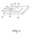
- the heat emitter 14 may comprise at least one high speed infrared LED (IR LED) 24 .
- the IR LED 24 may generate high speed thermal flashes.
- the IR LED 24 may generate high speed thermal flashes.
- the IR LED 24 may be controlled by an electronic circuit external to the heat emitter 14 . In an embodiment, the IR LED 24 may be controlled by an electronic circuit within the heat emitter 14 .
- the heat emitter 14 may comprise a plurality of high speed IR LEDs 24 .
- the plurality of IR LEDs 24 may be arranged in an array that corresponds to an array of IR sensor elements in the IR sensor 36 .
- Each IR LED 24 may be controlled to generate high speed thermal flashes one at a time.
- the plurality of IR LEDs 24 may be controlled to generate high speed thermal flashes randomly.
- the plurality of IR LEDs 24 may be controlled to generate high speed thermal flashes randomly.
- the plurality of IR LEDs 24 may be controlled to mimic a temperature pattern of a rail undercarriage component of a passing rail vehicle.
- the plurality of IR LEDs 24 may be controlled by an electronic circuit external to the heat emitter 14 .
- the plurality of IR LEDs 24 may be controlled by an electronic circuit within the heat emitter 14 .
- the heat emitter 14 may comprise a heat member 25 which is capable of producing thermal radiation.
- the heat member 25 may comprise a black surface 26 coupled to a resistor.
- the resistor may heat the black surface 26 .
- the black surface 26 may be superposed on the resistor.
- the resistor may be disposed in the heat emitter 14 so as not to interfere with the thermal radiation from the black surface 26 .
- the temperature of the black surface 24 may be regulated by varying the resistor.
- the heat member 25 may be controlled by an electronic circuit external to the heat emitter 14 . In an embodiment, the heat member 25 may be controlled by an electronic circuit within the heat emitter 14 .
- the heat emitter 14 may comprise a temperature sensor 28 .
- the temperature sensor 28 may sense the temperature of the black surface 26 .
- the temperature sensor 28 may allow the temperature of the black surface 26 to be controlled.
- the temperature sensor 28 may be disposed in the heat emitter 14 so as not to interfere with the thermal radiation from the black surface 26 .
- the heat emitter 14 may comprise both the heat member 25 and the IR LED 24 .
- the heat member 25 and the IR LED 24 may be provided on the heat emitter 14 such that the IR emissions from either sources are detectable by the IR sensor 36 .
- the heat member 25 and the IR LED 24 may be disposed on a flat surface of the heat emitter 14 .
- the heat member 25 may be positioned adjacent to the IR LED 24 .
- the heat emitter 14 may comprise either the heat member 25 or the IR LED 24 .
- the heat member 25 or the IR LED 24 may be disposed on the heat emitter 14 such that the IR emissions may be detectable by the IR sensor 36 .
- the support 18 may be positioned to the side of the track 30 .
- the support 18 may comprise of upright beam 19 .
- the beam 19 may extend perpendicularly relative to the track 30 .
- the beam 19 may have a cross beam 17 cantilevered to the beam 19 .
- the cross beam 17 may be positioned at a height that is greater than the highest part of the rail vehicle.
- the beam 19 may be positioned away from the track 30 .
- the position of the support 18 may correspond with the rail bed of the track 30 wherein IR sensor 36 or IR sensors 36 are located.
- the support 18 may support the heat emitter 14 at a position suitable for testing the IR sensor 36 .
- the support 18 may support the heat emitter 14 at a position that is spaced from the passage of the rail vehicle.
- the heat emitter 14 may be in a position located away from the passage of the rail vehicle while suitable for testing the IR sensor 36 .
- the heat emitter 14 may be positioned over the track 30 .
- the heat emitter 14 may be positioned to the side of the track 30 and supported above the level of the track 30 .
- the heat emitter 14 may be installed on the support 18 to receive a scanning beam from the IR sensor 36 which is orientated to obtain IR emission data from the one of the rail vehicle undercarriage components.
- the direction of IR emissions of the heat member 25 and the IR LED 24 on the heat emitter 14 may be indicated by the line 12 .
- the direction of IR emissions of the heat member 25 and the IR LED 24 may be detected by the IR sensor 36 .
- the direction of IR emissions of either the heat member 25 or the IR LED 24 on the heat emitter 14 may be indicated by the line 12 .
- the direction of IR emissions of the heat member 25 or the IR LED 24 may be detected by the IR sensor 36 .
- the test apparatus 10 may comprise a plurality of heat emitters 14 .
- the number of heat emitters 14 may correspond to the number of IR sensors 36 that are installed in the rail bed of the track 30 .
- the support 18 may support the heat emitters 14 at specific positions that are suitable for testing respective IR sensor 36 .
- the support 18 may support the heat emitters 14 at positions that are spaced from the passage of the rail vehicle.
- the heat emitters 14 may be in positions located away from the passage of the rail vehicle while suitable for testing the respective IR sensors 36 .
- the heat emitters 14 may be positioned over the track 30 .
- the support 18 may support the heat emitters 14 in specific orientations for directing the IR emissions at the respective IR sensors 36 .
- the emission lines 12 may indicate the directions of the IR emissions from each heat emitter 14 to the respective IR sensor 36 .
- the plurality of heat emitters 14 may be installed on the support 18 at the respective positions so as to receive scanning beams from the corresponding IR sensors 36 that are orientated to obtain IR emission data from the respective rail vehicle undercarriage components.
- the direction of IR emissions of the heat members 25 and the IR LEDs 24 on each heat emitter 14 may be indicated by the lines 12 .
- the direction of IR emissions of the heat members 25 and the IR LEDs 24 on each heat emitter 14 may be detected by the respective IR sensor 36 .
- the direction of IR emissions of the either the heat members 25 or the IR LEDs 24 on each heat emitter 14 may be indicated by the lines 12 .
- the direction of IR emissions of the heat members 25 or the IR LEDs 24 on each heat emitter 14 may be detected by the respective IR sensor 36 .
- the test apparatus 10 may comprise a test circuit 20 .
- the test circuit 20 may connect the heat emitter 14 to a controller 22 .
- the test circuit 20 may connect the plurality of heat emitters 14 to a controller 22 .
- the external electronic circuit controlling the IR LEDs 24 or the heat members 25 may be the test circuit 20 connected to the controller 22.
- the test apparatus 10 may comprise a wheel sensor 50 that is connected to the controller 22 .
- the test apparatus 10 may comprise a plurality of wheel sensors 50 that are each connected to the controller 22 .
- the controller 22 may be connected to the wheel sensors 50 and the IR sensors 36 .
- the controller 22 may be connected to a sensor controller 23 .
- the sensor controller 23 may control the IR sensors 36 .
- the sensor controller 23 may activate the IR sensors 36 to detect for IR emissions.
- the sensor controller 23 may generate IR data based on the detected IR emissions.
- a method of testing an IR sensor 36 of a rail vehicle undercarriage component may comprise the following steps.
- a heat emitter 14 may be provided for producing IR emissions at a reference temperature.
- the heat emitter 14 may be supported on a support 18 at a position spaced from the passage of the rail vehicle.
- the heat emitter 14 may be supported on a support 18 in an orientation for directing the IR emissions at the IR sensor 36 .
- the heat emitter 14 may be activated to produce IR emissions at the reference temperature.
- the reference temperature of the IR emissions and the temperature detected by the IR sensor 36 may be compared.
- the step of activating the heat emitter 14 may comprise generating a high speed thermal flash from the high speed IR LED 24 .
- the step of activating the heat emitter 14 may comprise generating high speed thermal flashes from the plurality of high speed IR LEDs 24 .
- the plurality of IR LEDs 24 may generate flashes which simulate the passage of a rail vehicle. This test may enable verification of the correct positioning of the scanning window.
- the scanning window may correspond to the target scanning area of a rail vehicle undercarriage component
- the controller 22 may generate signals that simulate the wheel signals of a passing rail vehicle travelling at a known speed.
- the simulated wheel signals may simultaneously trigger the test apparatus 10 and the IR sensors 36 .
- the simulated wheel signals may be transmitted to the IR LEDs 24 to generate thermal flashes.
- the thermal flashes may be at a pre-selected reference temperature.
- the IR LEDs 24 may generate thermal flashes sequentially.
- the simulated wheel signals may be transmitted to the sensor controller 23 for activation of the IR sensors 36 to detect the IR emissions corresponding to the thermal flashes.
- the IR emissions may be indicative of the temperature of the thermal flashes from the array of IR sensors 36 .
- the controller 22 may compare the reference temperature of the thermal flashes generated by the IR LEDs 24 and the temperature which is obtained from the IR emissions detected by the IR sensor 36 . A mismatch in the reference temperature and the detected temperature may send an error signal. The controller 22 may check if an alarm has been raised if the reference temperature is greater than a pre-set threshold temperature. An error signal may be sent if an alarm is not raised when the reference temperature is greater than a pre-set threshold temperature.
- the foregoing steps may enable the IR sensors 36 to be tested for the following functions: measurement of synchronicity with the IR LEDs 24 , velocity calculation of the rail vehicle and the reduction factor of the acquired IR emissions data.
- the step of activating the heat emitter 14 may comprise heating the black surface 26 by the resistor.
- the controller 22 may transmit signals to the resistor so as to heat the black surface 26 to a pre-selected temperature.
- the temperature of the black surface 26 may be checked by the controller 22 through the temperature sensor 28 .
- the controller 22 may transmit signals to the sensor controller 23 for activation of the IR sensors 36 to detect the IR emissions corresponding to the thermal radiation from the black surface 26 when the temperature of the black surface 24 reaches a pre-selected temperature.
- the IR emissions may be indicative of the temperature of the thermal radiation from the black surface 24 .
- the controller 22 may compare the reference temperature of the thermal radiation from the black surface 26 and the temperature which is obtained from the IR emissions detected by the IR sensor 36 . A mismatch in the reference temperature and the detected temperature may send an error signal. The controller 22 may check if an alarm has been raised if the reference temperature is greater than a pre-set threshold temperature. An error signal may be sent if an alarm is not raised when the reference temperature is greater than a pre-set threshold temperature.
- the foregoing steps may enable the IR sensors 36 to be tested for the following functions: IR sensor 36 alignment to the heat emitter 14 and the accuracy of the measurement by the IR sensor 36 .
- the heat member 25 may enable the measurement accuracy of the IR sensor 36 to be tested to a high level of accuracy since the reference temperature may be accurately controlled by the resistor and may be checked by the temperature sensor 28 .
- the reference temperature may be varied to specific pre-selected values through the controller 22 .
- the test apparatus 10 may be provided with a plurality of heat emitters 14 corresponding to a plurality of IR sensors 36 .
- Each heat emitter 14 may supply a reference temperature for detection by a corresponding IR sensor 36 .
- the step of activating the heat emitter 14 may comprise activating the plurality of heat emitters 14 one at a time.
- the plurality of heat emitters 14 may be activated in sequence.
- the plurality of heat emitters 14 may be activated randomly.
- the controller 22 may transmit signals resistor so as to heat the respective black surfaces 26 to a pre-selected temperature.
- the controller 22 may transmit signals to the sensor controller 23 for activation of the IR sensor 36 corresponding to the activated heat emitter 14 when the temperature of the black surfaces 26 reach the pre-selected temperature.
- the IR sensors 36 may be activated to detect the IR emissions corresponding to the thermal radiation from the respective black surfaces 26.
- the controller 22 may compare the reference temperature of the thermal radiation from the black surfaces 26 and the temperature which is obtained from the IR emissions detected by the IR sensors 36 . A mismatch in any one of the reference temperatures and the detected temperatures may send an error signal. The controller 22 may check if an alarm has been raised if the reference temperatures are greater than a pre-set threshold temperature. An error signal may be sent if an alarm is not raised when the reference temperatures are greater than a pre-set threshold temperature.
- the plurality of heat emitters 14 may be activated simultaneously.
- the controller 22 may transmit signals resistor so as to heat the respective black surfaces 26 to a pre-selected temperature.
- the controller 22 may transmit signals to the control circuit of the IR sensors 36 corresponding to the activated heat emitter 14 when the temperature of the black surfaces 26 reach the pre-selected temperature.
- the IR sensors 36 may be activated alternatively to detect the IR emissions corresponding to the thermal radiation from the respective black surfaces 26 .
- the plurality of IR sensors 36 may be activated in sequence.
- the plurality of IR sensors 36 may be activated randomly.
- the step of activating the heat emitter 14 may comprise activation of a wheel sensor 50 .
- the controller 22 may monitor the wheel sensor 50 and record the signals and the information relating to the passage of a rail vehicle used by the IR sensors 36 to detect the IR emissions from an undercarriage component. After a time lag the controller may activate the heat emitter 14 and may transmit signals to the IR sensor 36 .
- the controller 22 may use the signals and information from the wheel sensor 50 to issue signals which replicate signals from the wheel sensor 50 .
- the replicated signals from the controller may simulate the wheel signals of a passing rail vehicle travelling at a known speed.
- the replicated wheel signals may simultaneously trigger the test apparatus 10 and the IR sensors 36 .
- the replicated wheel signals may be transmitted to the IR LEDs 24 to generate thermal flashes.
- the thermal flashes may be at a pre-selected reference temperature.
- the IR LEDs 24 may generate thermal flashes sequentially.
- the replicated wheel signals may be transmitted to the sensor controller 23 for activation of the IR sensors 36 to detect the IR emissions corresponding to the thermal flashes.
- the IR emissions may be indicative of the temperature of the thermal flashes from the array of IR sensors 36 .
- the controller 22 may compare the reference temperature of the thermal flashes generated by the IR LEDs 24 and the temperature which is obtained from the IR emissions detected by the IR sensor 36 . A mismatch in the reference temperature and the detected temperature may send an error signal. The controller 22 may check if an alarm has been raised if the reference temperature is greater than a pre-set threshold temperature. An error signal may be sent if an alarm is not raised when the reference temperature is greater than a pre-set threshold temperature.
- the above tests may be performed by the controller 22 periodically at pre-determined time intervals.
- This disclosure describes a test apparatus 10 for testing an IR sensor 36 which may be used to obtain data, such as infrared IR emission data.
- the data may be obtained by sensing a wheel 44 or a wheel bearing 46, 48 of a vehicle, such as a rail car, passing over the IR sensor 36.
- the test apparatus 10 may perform a test on the IR sensor 36 in the absence of a passing rail vehicle or immediately upon passage of a rail vehicle.
- the test apparatus 10 may test the accuracy of the infrared IR emission data obtained by the IR sensor 36 .
- the test apparatus 10 may test the alignment of the IR sensor 36 .
- the test apparatus 10 may test the correct position of a measuring window of the IR sensor 36 .
- references signs have been included for the sole purpose of increasing the intelligibility of the claims and accordingly, neither the reference signs nor their absence have any limiting effect on the technical features as described above or on the scope of any claim elements.
Landscapes
- Physics & Mathematics (AREA)
- General Physics & Mathematics (AREA)
- Spectroscopy & Molecular Physics (AREA)
- Engineering & Computer Science (AREA)
- Mechanical Engineering (AREA)
- Testing Of Devices, Machine Parts, Or Other Structures Thereof (AREA)
- Investigating Or Analyzing Materials Using Thermal Means (AREA)
- Machines For Laying And Maintaining Railways (AREA)
- Testing Electric Properties And Detecting Electric Faults (AREA)
Priority Applications (5)
| Application Number | Priority Date | Filing Date | Title |
|---|---|---|---|
| EP11185451.9A EP2584329A1 (de) | 2011-10-17 | 2011-10-17 | Vorrichtung zum Testen eines Sensors für Zugunterwagentemperaturen |
| ES12150966.5T ES2600032T3 (es) | 2011-10-17 | 2012-01-12 | Aparato para someter a prueba un sensor de temperaturas de bastidor de trenes |
| EP12150966.5A EP2584330B1 (de) | 2011-10-17 | 2012-01-12 | Vorrichtung zum Testen eines Sensors für Zugunterwagentemperaturen |
| US13/605,764 US8944677B2 (en) | 2011-10-17 | 2012-09-06 | Device for testing a sensor of train undercarriage temperatures |
| US14/577,799 US9423305B2 (en) | 2011-10-17 | 2014-12-19 | Device for testing a sensor of train undercarriage temperatures |
Applications Claiming Priority (1)
| Application Number | Priority Date | Filing Date | Title |
|---|---|---|---|
| EP11185451.9A EP2584329A1 (de) | 2011-10-17 | 2011-10-17 | Vorrichtung zum Testen eines Sensors für Zugunterwagentemperaturen |
Publications (1)
| Publication Number | Publication Date |
|---|---|
| EP2584329A1 true EP2584329A1 (de) | 2013-04-24 |
Family
ID=45443054
Family Applications (2)
| Application Number | Title | Priority Date | Filing Date |
|---|---|---|---|
| EP11185451.9A Ceased EP2584329A1 (de) | 2011-10-17 | 2011-10-17 | Vorrichtung zum Testen eines Sensors für Zugunterwagentemperaturen |
| EP12150966.5A Active EP2584330B1 (de) | 2011-10-17 | 2012-01-12 | Vorrichtung zum Testen eines Sensors für Zugunterwagentemperaturen |
Family Applications After (1)
| Application Number | Title | Priority Date | Filing Date |
|---|---|---|---|
| EP12150966.5A Active EP2584330B1 (de) | 2011-10-17 | 2012-01-12 | Vorrichtung zum Testen eines Sensors für Zugunterwagentemperaturen |
Country Status (3)
| Country | Link |
|---|---|
| US (2) | US8944677B2 (de) |
| EP (2) | EP2584329A1 (de) |
| ES (1) | ES2600032T3 (de) |
Cited By (1)
| Publication number | Priority date | Publication date | Assignee | Title |
|---|---|---|---|---|
| EP2778012A1 (de) * | 2013-03-15 | 2014-09-17 | Progress Rail Inspection & Information Systems S.r.l. | Integritätsprüfung von IR-Detektoren für ein Schienenfahrzeug |
Families Citing this family (9)
| Publication number | Priority date | Publication date | Assignee | Title |
|---|---|---|---|---|
| WO2009088946A1 (en) * | 2008-01-03 | 2009-07-16 | Iwapi, Inc. | Integrated rail efficiency and safety support system |
| EP2584329A1 (de) | 2011-10-17 | 2013-04-24 | Progress Rail Services Corporation | Vorrichtung zum Testen eines Sensors für Zugunterwagentemperaturen |
| CN104330163B (zh) * | 2014-11-07 | 2018-05-04 | 中国兵器工业集团第二一四研究所苏州研发中心 | 新型钢轨测温计 |
| CN105292174B (zh) * | 2015-11-04 | 2018-04-06 | 南京富岛信息工程有限公司 | 一种基于信号特征的红外热轴音频通道故障诊断方法 |
| CN106197681A (zh) * | 2016-08-02 | 2016-12-07 | 北京殷图网联科技股份有限公司 | 高压开关柜在线测温装置、方法以及系统 |
| EP3354532B1 (de) * | 2017-01-26 | 2020-05-27 | Rail Vision Europe Ltd | Fahrzeugmontiertes überwachungssystem |
| WO2019136620A1 (zh) * | 2018-01-10 | 2019-07-18 | 北京东方瑞威科技发展股份有限公司 | 一种铁路超偏载系统及检测方法 |
| JP7160593B2 (ja) * | 2018-08-08 | 2022-10-25 | 東海旅客鉄道株式会社 | 温度異常検出システム及び温度異常検出方法 |
| CN111579091A (zh) * | 2020-06-01 | 2020-08-25 | 杭州岚达科技有限公司 | 一种红外温度监测系统 |
Citations (5)
| Publication number | Priority date | Publication date | Assignee | Title |
|---|---|---|---|---|
| US5060890A (en) * | 1988-10-11 | 1991-10-29 | Harmon Industries, Inc. | Detection of overheated railroad wheel and axle components |
| US5100243A (en) * | 1990-12-12 | 1992-03-31 | Servo Corporation Of America | Self-calibrating hot wheel detector for railroads |
| US5292090A (en) * | 1992-12-02 | 1994-03-08 | Meg Trans Corp. | Simulator for railroad hot wheel detector |
| EP0670255A1 (de) * | 1994-03-02 | 1995-09-06 | VAE Aktiengesellschaft | Prüfgerät für die Kalibrierung von Heissläufer- und Festbremsortungsanlagen |
| DE19633950A1 (de) * | 1995-09-05 | 1997-03-06 | Vae Ag | Prüfstrahler zur Kalibrierung von Infrarotdetektoren |
Family Cites Families (10)
| Publication number | Priority date | Publication date | Assignee | Title |
|---|---|---|---|---|
| US3086108A (en) * | 1960-03-22 | 1963-04-16 | Charles G Kaehms | Infrared hotbox detection system |
| US4878437A (en) * | 1988-03-17 | 1989-11-07 | Consolidated Rail Corporation | Hot bearing simulator |
| US4974797A (en) * | 1988-03-17 | 1990-12-04 | Consolidated Rail Corporation | Hot bearing simulator |
| US5149025A (en) * | 1988-10-11 | 1992-09-22 | Harmon Industries, Inc. | Detection of overheated railroad wheel and axle components |
| GB9106234D0 (en) * | 1991-03-23 | 1991-05-08 | Powell Duffryn Standard Ltd | Improvements in or relating to the detection of overheated bearings in railway vehicles |
| US6335548B1 (en) * | 1999-03-15 | 2002-01-01 | Gentex Corporation | Semiconductor radiation emitter package |
| US6791088B1 (en) * | 2001-05-04 | 2004-09-14 | Twin Rivers Engineering, Inc. | Infrared leak detector |
| TWI313614B (en) * | 2006-05-11 | 2009-08-21 | An infrared ray generator | |
| EP2584329A1 (de) | 2011-10-17 | 2013-04-24 | Progress Rail Services Corporation | Vorrichtung zum Testen eines Sensors für Zugunterwagentemperaturen |
| US20140321501A1 (en) * | 2013-04-24 | 2014-10-30 | Progress Rail Services Corporation | Hot bearing detection system and method |
-
2011
- 2011-10-17 EP EP11185451.9A patent/EP2584329A1/de not_active Ceased
-
2012
- 2012-01-12 EP EP12150966.5A patent/EP2584330B1/de active Active
- 2012-01-12 ES ES12150966.5T patent/ES2600032T3/es active Active
- 2012-09-06 US US13/605,764 patent/US8944677B2/en active Active
-
2014
- 2014-12-19 US US14/577,799 patent/US9423305B2/en not_active Expired - Fee Related
Patent Citations (5)
| Publication number | Priority date | Publication date | Assignee | Title |
|---|---|---|---|---|
| US5060890A (en) * | 1988-10-11 | 1991-10-29 | Harmon Industries, Inc. | Detection of overheated railroad wheel and axle components |
| US5100243A (en) * | 1990-12-12 | 1992-03-31 | Servo Corporation Of America | Self-calibrating hot wheel detector for railroads |
| US5292090A (en) * | 1992-12-02 | 1994-03-08 | Meg Trans Corp. | Simulator for railroad hot wheel detector |
| EP0670255A1 (de) * | 1994-03-02 | 1995-09-06 | VAE Aktiengesellschaft | Prüfgerät für die Kalibrierung von Heissläufer- und Festbremsortungsanlagen |
| DE19633950A1 (de) * | 1995-09-05 | 1997-03-06 | Vae Ag | Prüfstrahler zur Kalibrierung von Infrarotdetektoren |
Cited By (1)
| Publication number | Priority date | Publication date | Assignee | Title |
|---|---|---|---|---|
| EP2778012A1 (de) * | 2013-03-15 | 2014-09-17 | Progress Rail Inspection & Information Systems S.r.l. | Integritätsprüfung von IR-Detektoren für ein Schienenfahrzeug |
Also Published As
| Publication number | Publication date |
|---|---|
| US9423305B2 (en) | 2016-08-23 |
| EP2584330A1 (de) | 2013-04-24 |
| US20150131696A1 (en) | 2015-05-14 |
| US20130094535A1 (en) | 2013-04-18 |
| EP2584330B1 (de) | 2016-08-17 |
| US8944677B2 (en) | 2015-02-03 |
| ES2600032T3 (es) | 2017-02-06 |
Similar Documents
| Publication | Publication Date | Title |
|---|---|---|
| US8944677B2 (en) | Device for testing a sensor of train undercarriage temperatures | |
| CN107406090B (zh) | 异常车辆动态检测 | |
| CN101072985B (zh) | 列车车轮轴承温度检测 | |
| US9212902B2 (en) | Distance image obtaining system for track | |
| US6416020B1 (en) | Method and apparatus for detecting defective track wheels | |
| CN106163900A (zh) | 用于铁路车辆的障碍物和脱轨的检测装置 | |
| JP4008082B2 (ja) | レールの締結具の脱落の検知装置及び方法、並びに、レールの位置の検知方法 | |
| AU2005265414A1 (en) | Apparatus for detecting hunting and angle of attack of a rail vehicle wheelset | |
| ES2808103T3 (es) | Procedimiento y dispositivo para la prueba automática de los frenos de un vehículo guiado sobre raíles | |
| Nayan et al. | An IoT based real-time railway fishplate monitoring system for early warning | |
| US5292090A (en) | Simulator for railroad hot wheel detector | |
| JP6148643B2 (ja) | 列車検出装置 | |
| JP6672040B2 (ja) | 鉄道車両用温度検知装置 | |
| CA2870425C (en) | Automated in motion railway seismic wheel failure detection system | |
| EP2778012B1 (de) | Integritätsprüfung von IR-Detektoren für ein Schienenfahrzeug | |
| KR101221028B1 (ko) | 철도 차량과 터널 내 시설물과의 간격 측정 시스템 | |
| JP2016126015A (ja) | 床下機器監視システム、設置条件算出方法 | |
| EP4682018A1 (de) | Messvorrichtung für längsbewegungen oder schienenverschiebungen, gesteuert von sich bewegenden schienenfahrzeugen | |
| JP7701701B1 (ja) | 弛緩判定システムを備えた軌道点検装置 | |
| CN110207589B (zh) | 动态标定系统及方法 | |
| JP3600046B2 (ja) | 車両の床下監視装置 | |
| WO2021186235A1 (en) | Control device for continuous diagnostics of railway infrastructure | |
| JPH0682344A (ja) | 車両異常検出装置 | |
| CA2127837A1 (en) | Hot bearing simulator | |
| KR20190008754A (ko) | 궤도 안전 진단 시스템 및 방법 |
Legal Events
| Date | Code | Title | Description |
|---|---|---|---|
| PUAI | Public reference made under article 153(3) epc to a published international application that has entered the european phase |
Free format text: ORIGINAL CODE: 0009012 |
|
| AK | Designated contracting states |
Kind code of ref document: A1 Designated state(s): AL AT BE BG CH CY CZ DE DK EE ES FI FR GB GR HR HU IE IS IT LI LT LU LV MC MK MT NL NO PL PT RO RS SE SI SK SM TR |
|
| AX | Request for extension of the european patent |
Extension state: BA ME |
|
| 17P | Request for examination filed |
Effective date: 20131024 |
|
| RBV | Designated contracting states (corrected) |
Designated state(s): AL AT BE BG CH CY CZ DE DK EE ES FI FR GB GR HR HU IE IS IT LI LT LU LV MC MK MT NL NO PL PT RO RS SE SI SK SM TR |
|
| 17Q | First examination report despatched |
Effective date: 20131127 |
|
| STAA | Information on the status of an ep patent application or granted ep patent |
Free format text: STATUS: THE APPLICATION HAS BEEN REFUSED |
|
| 18R | Application refused |
Effective date: 20141209 |