EP2584364A1 - Selbstzentrierender, geteilter mehradriger Stromsensor - Google Patents
Selbstzentrierender, geteilter mehradriger Stromsensor Download PDFInfo
- Publication number
- EP2584364A1 EP2584364A1 EP11185788.4A EP11185788A EP2584364A1 EP 2584364 A1 EP2584364 A1 EP 2584364A1 EP 11185788 A EP11185788 A EP 11185788A EP 2584364 A1 EP2584364 A1 EP 2584364A1
- Authority
- EP
- European Patent Office
- Prior art keywords
- sensor device
- sensor
- cable
- housing
- current
- Prior art date
- Legal status (The legal status is an assumption and is not a legal conclusion. Google has not performed a legal analysis and makes no representation as to the accuracy of the status listed.)
- Withdrawn
Links
- 238000005259 measurement Methods 0.000 claims abstract description 15
- 238000000034 method Methods 0.000 claims abstract description 14
- 230000008569 process Effects 0.000 claims abstract description 6
- 239000012777 electrically insulating material Substances 0.000 claims abstract 3
- 230000003287 optical effect Effects 0.000 claims description 17
- 238000003306 harvesting Methods 0.000 claims description 16
- 238000012545 processing Methods 0.000 claims description 7
- 229920002943 EPDM rubber Polymers 0.000 claims description 4
- 238000004146 energy storage Methods 0.000 claims description 4
- 230000004907 flux Effects 0.000 claims description 4
- 239000004973 liquid crystal related substance Substances 0.000 claims description 3
- 229920002635 polyurethane Polymers 0.000 claims description 3
- 239000004814 polyurethane Substances 0.000 claims description 3
- 229920001084 poly(chloroprene) Polymers 0.000 claims description 2
- 239000004800 polyvinyl chloride Substances 0.000 claims description 2
- 150000002825 nitriles Chemical class 0.000 claims 1
- 229920002379 silicone rubber Polymers 0.000 claims 1
- 239000004945 silicone rubber Substances 0.000 claims 1
- 239000004020 conductor Substances 0.000 description 38
- 239000000463 material Substances 0.000 description 9
- 238000004804 winding Methods 0.000 description 8
- 241000234295 Musa Species 0.000 description 5
- 235000018290 Musa x paradisiaca Nutrition 0.000 description 5
- 230000008901 benefit Effects 0.000 description 5
- 150000001875 compounds Chemical class 0.000 description 5
- 238000009434 installation Methods 0.000 description 5
- 230000010354 integration Effects 0.000 description 4
- 238000000465 moulding Methods 0.000 description 4
- 239000004065 semiconductor Substances 0.000 description 4
- 230000000007 visual effect Effects 0.000 description 4
- 239000003086 colorant Substances 0.000 description 3
- 238000013461 design Methods 0.000 description 3
- 230000035699 permeability Effects 0.000 description 3
- 229920005749 polyurethane resin Polymers 0.000 description 3
- 239000000523 sample Substances 0.000 description 3
- 238000013459 approach Methods 0.000 description 2
- 239000000428 dust Substances 0.000 description 2
- 229920001971 elastomer Polymers 0.000 description 2
- 239000012530 fluid Substances 0.000 description 2
- 239000013307 optical fiber Substances 0.000 description 2
- 238000007781 pre-processing Methods 0.000 description 2
- 230000004044 response Effects 0.000 description 2
- 239000012780 transparent material Substances 0.000 description 2
- 208000032365 Electromagnetic interference Diseases 0.000 description 1
- 241000446313 Lamella Species 0.000 description 1
- 230000005540 biological transmission Effects 0.000 description 1
- 239000003990 capacitor Substances 0.000 description 1
- 230000008859 change Effects 0.000 description 1
- 239000012141 concentrate Substances 0.000 description 1
- 230000003247 decreasing effect Effects 0.000 description 1
- 230000000694 effects Effects 0.000 description 1
- 230000005489 elastic deformation Effects 0.000 description 1
- 230000005611 electricity Effects 0.000 description 1
- 239000007789 gas Substances 0.000 description 1
- 239000011521 glass Substances 0.000 description 1
- 238000005286 illumination Methods 0.000 description 1
- 230000006698 induction Effects 0.000 description 1
- 238000003780 insertion Methods 0.000 description 1
- 230000037431 insertion Effects 0.000 description 1
- 238000009413 insulation Methods 0.000 description 1
- 230000002452 interceptive effect Effects 0.000 description 1
- 239000007788 liquid Substances 0.000 description 1
- 230000005415 magnetization Effects 0.000 description 1
- 238000000691 measurement method Methods 0.000 description 1
- 230000007246 mechanism Effects 0.000 description 1
- 230000003278 mimic effect Effects 0.000 description 1
- 239000002480 mineral oil Substances 0.000 description 1
- 235000010446 mineral oil Nutrition 0.000 description 1
- 230000004048 modification Effects 0.000 description 1
- 238000012986 modification Methods 0.000 description 1
- 125000005245 nitryl group Chemical group [N+](=O)([O-])* 0.000 description 1
- 238000004806 packaging method and process Methods 0.000 description 1
- 230000010287 polarization Effects 0.000 description 1
- 229920001296 polysiloxane Polymers 0.000 description 1
- 229920005989 resin Polymers 0.000 description 1
- 239000011347 resin Substances 0.000 description 1
- 238000010079 rubber tapping Methods 0.000 description 1
- 238000009738 saturating Methods 0.000 description 1
- 239000007787 solid Substances 0.000 description 1
- 238000003860 storage Methods 0.000 description 1
- 230000007704 transition Effects 0.000 description 1
- XLYOFNOQVPJJNP-UHFFFAOYSA-N water Substances O XLYOFNOQVPJJNP-UHFFFAOYSA-N 0.000 description 1
Images


Classifications
-
- G—PHYSICS
- G01—MEASURING; TESTING
- G01R—MEASURING ELECTRIC VARIABLES; MEASURING MAGNETIC VARIABLES
- G01R15/00—Details of measuring arrangements of the types provided for in groups G01R17/00 - G01R29/00, G01R33/00 - G01R33/26 or G01R35/00
- G01R15/14—Adaptations providing voltage or current isolation, e.g. for high-voltage or high-current networks
- G01R15/20—Adaptations providing voltage or current isolation, e.g. for high-voltage or high-current networks using galvano-magnetic devices, e.g. Hall-effect devices, i.e. measuring a magnetic field via the interaction between a current and a magnetic field, e.g. magneto resistive or Hall effect devices
- G01R15/207—Constructional details independent of the type of device used
-
- G—PHYSICS
- G01—MEASURING; TESTING
- G01R—MEASURING ELECTRIC VARIABLES; MEASURING MAGNETIC VARIABLES
- G01R15/00—Details of measuring arrangements of the types provided for in groups G01R17/00 - G01R29/00, G01R33/00 - G01R33/26 or G01R35/00
- G01R15/14—Adaptations providing voltage or current isolation, e.g. for high-voltage or high-current networks
- G01R15/146—Measuring arrangements for current not covered by other subgroups of G01R15/14, e.g. using current dividers, shunts, or measuring a voltage drop
- G01R15/148—Measuring arrangements for current not covered by other subgroups of G01R15/14, e.g. using current dividers, shunts, or measuring a voltage drop involving the measuring of a magnetic field or electric field
-
- G—PHYSICS
- G01—MEASURING; TESTING
- G01R—MEASURING ELECTRIC VARIABLES; MEASURING MAGNETIC VARIABLES
- G01R15/00—Details of measuring arrangements of the types provided for in groups G01R17/00 - G01R29/00, G01R33/00 - G01R33/26 or G01R35/00
- G01R15/14—Adaptations providing voltage or current isolation, e.g. for high-voltage or high-current networks
- G01R15/18—Adaptations providing voltage or current isolation, e.g. for high-voltage or high-current networks using inductive devices, e.g. transformers
- G01R15/181—Adaptations providing voltage or current isolation, e.g. for high-voltage or high-current networks using inductive devices, e.g. transformers using coils without a magnetic core, e.g. Rogowski coils
-
- G—PHYSICS
- G01—MEASURING; TESTING
- G01R—MEASURING ELECTRIC VARIABLES; MEASURING MAGNETIC VARIABLES
- G01R15/00—Details of measuring arrangements of the types provided for in groups G01R17/00 - G01R29/00, G01R33/00 - G01R33/26 or G01R35/00
- G01R15/14—Adaptations providing voltage or current isolation, e.g. for high-voltage or high-current networks
- G01R15/24—Adaptations providing voltage or current isolation, e.g. for high-voltage or high-current networks using light-modulating devices
- G01R15/245—Adaptations providing voltage or current isolation, e.g. for high-voltage or high-current networks using light-modulating devices using magneto-optical modulators, e.g. based on the Faraday or Cotton-Mouton effect
Definitions
- the present invention relates to sensor devices, in particular to those which are adapted to be attached to cables. Furthermore, the present invention relates to a method for fabricating such a sensor device.
- sensor devices are needed which can be attached to the cable in a way that the position of a sensor element is defined such that it enables maximum accuracy of the measurement.
- electrically conductive cables are considered as objects to be monitored, the principles of the present invention may also be applied to all sorts of conducts for gases and liquid fluids or to optical fibers.
- the type of sensor element which is contained in the sensor device according to the present invention can be different. Further, also a plurality of sensor types may be incorporated within the housing according to the present invention. In the following, as an example mostly, an application as a current sensor is envisaged.
- Current transformers consist of two or more windings, each winding consisting of one or more turns of wire, around a continuous core having a high magnetic permeability to concentrate the magnetic flux lines generated by current flowing in the windings. The ratio of turns in the windings determines the turns ratio of the transformer.
- Clamp-on current transformers introduce a break in the core to permit its installation around a current carrying conductor without breaking the conductor.
- Current transformers only respond to AC currents unless special steps are taken to actively switch the magnetization direction or strength in the core.
- current transformers become extremely large and heavy and contain insulating mineral oil in order to satisfy the dielectric requirements of the application.
- a Rogowski coil consists of a coil winding placed around a core having a magnetic permeability similar to air.
- a current-carrying conductor is passed through the coil, and generates an output voltage that is proportional to the time derivative of the current in the conductor.
- the real-time current can be estimated by time-integrating the signal from the Rogowski coil.
- Rogoswki coils require an AC current to generate an output signal, and their output amplitude is proportional to the frequency, amplitude and differential of the current.
- a resistive shunt consists of a resistor connected to a current-carrying conductor in such a manner as to allow at least some of the conductor current to pass through the resistive element.
- the resulting voltage drop across the resistive element is a measure of the current flowing through the element.
- the resistive element can be placed in series with the current-carrying conductor, whereby all the conductor current passes through the resistive element, or it can be placed in parallel with a portion of the current-carrying conductor, whereby it shunts a known portion of the current away from the conductor.
- Resistive current sensors can measure AC or DC currents, and are relatively easy to use when the currents to be measured are small, i.e. less than 100 Amperes.
- Field sensors take advantage of the magnetic field generated by the current in a conductor. By placing a point magnetic field sensor such as a Hall sensor near the conductor, the sensor output signal is proportional to the current in the conductor. By using a magnetic field sensor of the proper type, this current sensor can respond to AC or DC currents, and can have a wide frequency response. Calibration is difficult to achieve or maintain with this approach. Stray magnetic fields generated by other currents located nearby will also cause measurement errors.
- Optical current sensors use the Faraday effect in an optical solid to change the travel time, polarization state or optical phase of an optical signal, in direct proportion to the magnetic field present along the optical path.
- the resulting signal is proportional to the current, and is substantially immune to interfering magnetic fields from other conductors, the position of the conductor relative to the sensor structure, and the size of the conductor.
- the sensor can be made to respond to DC or AC currents, and it can have a high bandwidth.
- Optical current sensors are difficult to design as a clamp-on device, and they suffer from high costs.
- the most accurate current sensors take advantage of Ampere's law, which states that the line integral of the magnetic field along a closed path encircling a current is proportional to the current. More importantly, the integral is not sensitive to the details of the path shape, the spatial distribution of the current within the closed integration path, or the presence of any currents that do not pass through the closed integration path.
- the current transformer achieves this by having a closed path of high permeability core.
- the Rogowski coil achieves this by having a coil encircling the conductor with uniform turns per inch along the winding.
- the optical current sensor achieves this by having an optical sensor element encircling the conductor, such as a block of glass through which a hole has been machined to allow a conductor to pass through and in which the optical beam propagates in a closed path encircling the hole, or an optical fiber that carries the optical signal and can be formed into a closed loop or loops around the current carrying conductor.
- an optical sensor element encircling the conductor, such as a block of glass through which a hole has been machined to allow a conductor to pass through and in which the optical beam propagates in a closed path encircling the hole, or an optical fiber that carries the optical signal and can be formed into a closed loop or loops around the current carrying conductor.
- the power utility industry measures current and voltage to calculate power flow and energy transferred between suppliers and customers.
- IEEE Institute for Electrical and Electronics Engineers
- IEC International Electricity Committee
- ANSI/IEEE Standard C57.13 requires that a current transformer must have an amplitude error of no greater than +/-0.3% and a phase angle error of no greater than +/-15 minutes of arc over a wide range of currents, regardless of temperature, stray magnetic fields, conductor size or installation environment.
- IEC Standard 60044-7 has a similar current transformer requirement of +/-0.2% magnitude error and +/-10 minutes of arc in phase angle error.
- the present invention is based on the idea of embedding sensor elements within a housing fabricated from a flexible material that is formed as one integral single part.
- the housing encases the sensor element and can be clamped onto the cable during a measurement process.
- same is elastically deformed.
- the advantage of this idea firstly lies in the fact that the installation is facilitated and the sensor elements are securely protected from moisture and physical damage.
- the sensor element comprises at least one current measurement device which can accurately measure the current in an electrical conductor without cutting or breaking the conductor.
- the sensor device may also comprise a voltage measurement device.
- a voltage sensor may advantageously provide further information on the electrical condition of the cable to be monitored.
- the voltage sensor can for instance comprise a voltage plate which is in direct contact with a semiconductor layer of the cable, the so-called semicon material. The voltage plate will sense the voltage in the internal conductor of the cable to be monitored and this signal will give a differential signal when compared with the ground plane.
- Part of such a voltage sensor can also be embedded in a stress relieve mechanism which forms part of a switch gear connection system, such as the RSTI product line of TE connectivity.
- the housing is formed by overmolding the sensor element directly.
- materials can be used for this overmolding step, such as polyvinyl chloride (PVC), silicone, rubber, neoprene, nitryl, ethylene propylene diene monomer (EPDM) rubber, or polyurethane.
- the housing may either be configured as a simple sensor probe, therefore containing only the sensor elements and optionally some signal pre-processing element, transmitting the measured signals to the outside by means of wireless techniques or electrically conductive leads.
- the required intelligence for evaluating the measured signals and display or warning devices of some sort may also be directly integrated within the housing.
- Fault current sensors may for instance contain an acoustic and/or optic warning device and may be fabricated with at least a part of the housing being transparent.
- a centro-symmetric form of the housing is advantageous. This may for instance be achieved by providing a ring-shaped sensor portion at the housing which accommodates the at least one sensor element.
- a secure centering of the housing with the embedded sensors with respect to the cable to be monitored can be achieved.
- the housing is provided with a slit-shaped opening that leaves in a radial direction an unobstructed gap for mounting the mounting sleeve on the cable.
- the mounting sleeve may have an inner surface which is either smooth or provided with radial or axial waves or protrusions, as this is known from rubber grommets.
- the mounting sleeve In order to adapt the sensor device to a particularly large range of cable diameters, at the mounting sleeve at least one resilient protrusion may be provided for adapting the inner cross-sectional dimension of the mounting sleeve to varying outer crossectional dimensions of the cable to be monitored.
- the ring-shaped sensor portion is connected via at least one bellows-shaped connection portion to such a mounting sleeve.
- the housing When mounting the sensor device at the cable to be monitored, the housing has to be deformed elastically, for instance by opening a crossection which is formed as a broken circle.
- RF radio frequency
- the choke coils can be connected in series, as shown in US 6,825,650 B1 .
- an electrically conductive shielding element for instance a braided tubular shield, can be provided around the RF chokes connected in series.
- a terminal portion of the sensor device may be located in the same region or diagonally opposing region as the slit-shaped opening provided at the housing.
- the sensor device maintains equidistance between each RF chokes after installation on the cable especially in relation to the RF chokes on either side of the slit.
- identification means such as coded resistors, may be introduced into the sensor device for providing an electronically readable identification means of the sensor device.
- the sensor device has an embedded electronic circuitry which is encased within the housing. This allows a compact sensor design with an enhanced functionality and accuracy, because no additional leads have to be provided for transporting the signals from the sensor elements to the necessary electronic circuitry. Furthermore, in outdoor applications or rough environments, the electronic circuitry is securely protected from dust and intrusion of water.
- the electronic circuit may comprise an integrator circuit and/or a circuit carrier with a complete signal processing unit.
- the electrical output signal from the RF chokes is a derivative of the current with respect to the time (di/dt).
- the signal can be passed through an electronic integration circuit, which may be powered externally.
- the electronic circuitry can be embedded into the molding compound such that the output signal is a true current wave form.
- a printed circuit board PCB
- a display unit such as a liquid crystal display, LCD, and/or a plurality of light-emitting diodes, LED, can be provided for indicating a status of the sensor device.
- a visual indicator can be given to an observer of the amount of current passing through the conductor.
- the LEDs can be controlled in response to the measured current in a way that no colour means no current, green colour means rated current, amber colour signifies high current and red colour indicates an excessive current.
- a flashing red LED signal could be used in order to indicate a fault condition existing on the cable.
- the LEDs can be made visible for an operator either by providing windows near the LEDs or by using a transparent material for the complete housing.
- the sensor device may comprise energy harvesting means which are able to harvest energy from the conductor, whereto the sensor is attached.
- energy harvesting coils can be embedded into the housing, for instance a polyurethane resin, in order to harvest power from the cable being monitored.
- Two flux concentrated type electronic units may be incorporated for harvesting the necessary power from the conductor and, furthermore, a storage device may also be included in the sensor device.
- Such an energy storage unit may be in the form of a battery, a super capacitor, or both.
- a compact stand-alone sensor unit can be provided, which does not have to rely on additional energy sources.
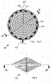
- FIG. 1 shows in a perspective view a sensor device 100 according to a first embodiment of the present invention.
- the shown sensor device is a current measurement device which can be mounted directly on a cable without disconnecting same.
- the sensor device 100 has a housing 102 which is formed as one single molded part from a flexible material.
- two mounting sleeves 108 are provided, which encompass the cable in a way like a grommet would do, with the difference that the radial circumference is not closed.
- the cable does not have to be slipped into the sensor device 100 and the mounting sleeves 108 in a longitudinal direction, but the sensor device 100 may be mounted in a direction across to the cable, due to the fact that a slit-shaped opening 106 is provided. Due to the fact that the housing material is flexible, the sensor device 100 may be opened-as indicated by arrows 110-wide enough to be mounted on the cable and will be clamped on the cable when releasing same.
- the ring-shaped sensor portion 112 encapsulates one or more sensor elements. In the case of an AC current sensor, this can be a plurality of RF chokes. Alternatively or additionally, also temperature sensors can be encapsulated in the housing material. In particular, the temperature sensors do not necessarily have to be located only in the sensor portion 112, but can also be arranged in direct contact with the cable, i. e. nearer to or directly within the mounting sleeves 108.
- a bellows-shaped connection portion 114 is provided between each of the mounting sleeves 108 and the sensor portion 112.
- the two connection portions 114 also can adjust for slight mounting tolerances in a longitudinal direction, when the sensor device is attached to the cable.
- the sensor elements which are embedded in the housing material 102 are thus accurately centered with respect to the cable to be monitored, as well as hermetically sealed against humidity, dust and physical damage.
- the sensor device may have an inner diameter of the mounting sleeves 108 of about 10 mm, an outer diameter of the sensor portion 112 of 150 mm and an inner diameter of the sensor portion of about 110 mm.
- the complete longitudinal outer dimension may amount to 76 mm from one mounting sleeve to the other.
- other dimensions can be chosen, depending on the dimensions of the cable or conduit whereto the sensor device 100 has to be mounted.
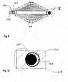
- FIGs. 2 and 3 show a longitudinal sectional view of the sensor device 100 of FIG. 8 and a detail of the sensor portion 112.
- the sensor portion 112 is formed like a circular ring being centered with respect to the middle axis 116.
- the housing 102 may be opened wide enough to attach the sensor device 100 to a cable, such that the central axis of the cable (not shown in the figure) coincides with the middle axis 116 of the sensor device 100.
- the sensor element 104 is either small enough or in itself flexible enough to follow this deformation. As shown in FIG.
- the sensor portion may encapsulate a plurality of serially connected RF chokes 118, which are surrounded by a shielding 120.
- the connecting wires between the individual chokes provide the necessary flexibility for opening the sensor device 100 when mounting same on a cable.
- the sensor elements 104 may also be formed by one single Rogowski coil, by evenly distributed Hall sensor elements, capacitive sensing elements, or other sensor elements.
- the mounting sleeves 108 have a smooth inner surface 122 which attaches the sensor device 100 to the outer surface of a cable (not shown in the figures).
- the inner surface 122 may also have a different shape, for instance by providing longitudinal protrusions or radial ring-shaped protrusions, as this is known from grommets.
- connection regions between the sensor portion 112 and the mounting sleeves 108, respectively, are formed with a step-wise decreasing diameter in order to form a flexible bellows-shaped connection portion 114. If necessary, the transition between the two diameters may of course also be linear.
- FIGs. 4 and 5 show top and side view of the sensor device according to FIG. 1 .
- the circular symmetric from of the housing is advantageous for a lot of current detecting techniques.
- preferable centrally symmetric footprints such as polygonal or rectangular, can be envisaged if necessary.
- the dimensions of the slit 106 are of course also arbitrary design measures, as long as it is ensured that the cable or conduit to be monitored will be centered coaxially with the middle of the sensor device 100.
- the housing 102 may for instance be fabricated in a way that the sidewalls 124 of the slit 106 touch each other in the mounted state. The housing 102, as shown in FIG.
- the device shown in FIGs. 1 to 5 may of course also be equipped with a terminal for electrically connecting same to a controller unit, a PC or the like.
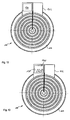
- the sensor device 100 comprises a cable leading to an external circuitry for processing the signals from the plurality of sensor elements.
- the cable 126 is connected, as shown in FIG. 7 , to the first end of a first coil and the second end of a last coil in order to output a sensor signal to an external signal processing unit.
- the sensor device 100 thus represents a current sensing probe without any further intelligence integrated in the housing 102.
- signal pre-processing electronic circuitry may also be integrated in the sensor device 100.
- a series of 16 RF chokes 118 are connected in series with each other, the first and the last one being arranged on the two opposing ends adjacent to the slit 106. Any other suitable number of chokes may of course also be used.
- the first and last wire 128, 130 of the series connection are led back in parallel to the chokes 118 and are connected to the cable 126 at a position opposite to the slit 106.
- the chokes and the wiring are encompassed by a shielding 120.
- FIG. 11 An alternative possibility of designing the mounting sleeve 108 is schematically shown in FIG. 11 .
- the sensor portion 112 is connected to only one mounting sleeve 108 by means of elastic lamellae 134.
- the mounting sleeve 108 is formed in a way that is has protrusions which are in contact with the cable.
- a slit 106 allows opening the sensor device as a whole in directions 110 and the insertion of a cable in a position centrally to the sensor portion 112.
- the sensor element according to the present invention may use a plurality of radio frequency chokes which have lacquered windings that are wrapped around a center core and are attached to an axial wire at either end.
- the flexible axial wire can be deformed when the housing 102 is opened.
- the RF chokes are connected in series end to end and the last inductor is connected to a wire that leads back from the last inductor to an output cable and leading out.
- a further possibility of connecting the coils to each other is to keep the windings which are wrapped around the core electrically separate from the core and from a center wire. This allows the larger core wires to be attached together in an electrical ring, thus having no break in the core/wire electrically and leading to a higher accuracy.
- the sensor device according to the present invention has the following advantages: Firstly, it overcomes the inaccuracy of the centering of current measuring devices on cables, wherein the error is the smaller, the closer the axis of the cable is to the center of the sensor device. The installation is facilitated and the sensors, in particular cores of coils, are securely protected from moisture and damage. In comparison for instance to conventional Rogowski coils, the sensor device according to the present invention is very cost-effective.
- a coded resistor can be included to identify which sensor is being used.
- the sensor device according to the present invention supports itself for clear viewing by a fault-finding electrician.
- the cores are self-saturating and provide an inherent self-protection for very high-current situations.
- the grommet-shaped mounting sleeves provide a ready made cable measurement device for an electrician.
- any sort of sensor device in particular a current measuring device, can be equipped with a very cost-effective means of measuring, in particular AC current.
- a further protrusion is created which encompasses an electronic integrator circuit 136.
- the signal can be passed through an electronic integration circuit 136 for recovering the actual current wave form i(t).
- the electronic integrator circuit 136 may be powered externally or by a power source integrated within the sensor device 100.
- the electronic circuitry 136 is embedded into the molding compound of the housing 102 in a way that the output signal is a true current wave form.
- FIG. 13 shows a further modification of the sensor device 100 according to the present invention.
- the protrusion of the housing 102 contains a complete electronic processing unit 138.
- the entire electronics required to measure and process the sensed current and/or voltage can be embedded by overmolding same when fabricating the sensor device according to the present invention.
- a display 140 can be provided for indicating a status of the cable to be measured to an operator. This display can for instance be a liquid crystal display, LCD.
- LED light emitting diodes
- LED light emitting diodes
- FIG. 14 By embedding such optical indicators 142 into the housing, an observer can have a visual indication of the status of the conductor to be measured.
- LEDs 142 with differing colours can be provided in a housing 102 formed by a polyurethane resin.
- any sufficiently transparent material can be used for ensuring that the illumination of the visual indicators is visible to a service technician.
- LEDs with differing colours would give the technician a quick information about the current passing through the conductor, for instance by defining that no colour means no current, that the green colour signifies a situation where the current is within the rated value, the amber colour signifies an elevated current level, and the red colour indicates to high a current. Additionally, also a flashing red colour could be used for identifying a fault condition existing on the cable.
- FIGs 14 and 15 one possible implementation of LEDs 142 is shown, where the LEDs are embedded inside the sensor portion 112 of the sensor device 100 and are visible through the compound of the housing 102, thus giving a visual indication of the status and possible fault conditions of the cable to be monitored. Additionally or alternatively, of course also acoustic warning means may be embedded within the housing 102.
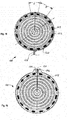
- FIGs 16 and 17 illustrate an option for powering the sensors directly from the cable to be monitored.
- energy harvesting means 144 are embedded within the housing 102 for harvesting energy from the conductor the sensor device 100 is attached around.
- Energy harvesting coils may for instance be embedded into polyurethane resin in order to harvest power from the cable being sensed.
- two flux concentrator type electronic units are provided for harvesting the power from the conductor and furthermore, an energy storage device can be included in the sensor device 100 which is charged by the energy harvesting units 144.
- Such an energy storage device can be formed by a battery and/or a supercapacitor (supercap).
- the RF chokes 118 should be arranged in positions which are diagonally opposing each other.
- the number itself is not critical, but only the fact that there is a pairing of chokes 118, one directly across from the other.
- the distances A and B, shown in FIG. 18 should be equal, so that the RF chokes 118 are uniformly distributed around the circumference of the sensor device 100.
- the wire is not brought back to exit on the opposite side of the slit 106 for inserting the cable, but is lead out where the slit 106 is provided at the mold.
- two mini banana plug receptacles 146 can be provided at each side of the slit 106 and be molded into the compound.
- the banana plug receptacles 146 are electrically connected with the two end chokes 118 and the top of the receptacles may be formed deeper than the mold surface, so that when the banana plugs are plugged into the receptacles 146, the compound extends over the plugs (not shown in the figure), thus providing a seal around the outside of the banana plug.
- the electrical connector being plugged into the sensor device can additionally serve as the mechanical clip to bring the two faces of the slit together and thus hold the sensor device in place.
- a cable 148 to be monitored usually comprises a semiconducting layer 150.
- a voltage plate 152 is provided in contact with the semiconductor material 150. The voltage plate 152 senses the voltage in the internal conductor with respect to ground 154 and the output signal V out indicates the voltage with respect to ground potential 154.
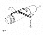
- FIG. 21 shows an embodiment, where the sensor device 100 is equipped with a voltage sensor according to the principle of FIG. 20 .
- a voltage sensor is embedded into the flexible multicore sensor device 100.
- the voltage sensor 152 is a conductor plate curving around the cable 148 being measured and is in contact with a semiconductor or insulation around the cable 148. The plate is held against the connector by the molding itself.
- two grounding rings 156 are provided at each of the mounting sleeves 108. These grounding rings 156 are electrically connected to each other by an insulated wire 158 running from one mounting sleeve 108 to the other.
- two wires 160 run across the axis of the cable and are connected to the exact center of the wire 158. As can be seen from FIG. 21 , one of the wires 160 is connected to the ground wire 158 and the other is connected with the voltage plate 152.
- the two horizontal wires 160 can be formed as a twisted pair configuration which allows the sensing of the voltage while almost eliminating any induced currents.
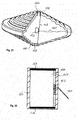
- FIG. 22 shows a voltage sensor that is provided separately from the sensor device 100 and can be combined therewith.
- a strain relief sleeve 162 is inserted onto a high voltage cable and under an elbow molding of existing connectors.
- the voltage sensing plate 152 is arranged between the semicon material 150 of the cable and the strain relief sleeve 162.
- Two electrically conductive rings 156 at the top and bottom of the sleeve 162 provide an electrical connection with the exposed semiconductor layer 150 of the cable being sensed.
- the grounding rings 156 are electrically wired to each other by means of connection 158, and a tap is taken of the exact center point of this connection.
- the second tap is taken of the voltage sensing plate 152 as close to the grounding tap as physically possible.
- Output wires 160 lead from these tapping points to a measuring unit (not shown in the figure).
- the configuration is designed to sense voltage and cancel out any induced current.
- the output wires 160 can of course also be formed in a twisted pair configuration in order to reduce current induction.
- sensor device housing 104 sensor element 106 slit for inserting the cable 108 mounting sleeves 110 direction for opening the housing 112 sensor portion 114 bellows-shaped connection portion 116 middle axis 118 RF choke 120 shielding 122 inner surface of mounting sleeves 124 inner wall of slit 126 cable of sensor device 128 first wire 130 last wire 132 connecting wires 134 elastic lamella 136 electronic integrator circuit 138 electronic processing unit 140 optical display unit, LCD 142 light emitting diodes 144 energy harvesting unit 146 mini banana plug receptacles 148 cable to be monitored 150 semiconducting layer 152 voltage plate 154 ground 156 grounding rings 158 insulated wire 160 output wires 162 strain relief sleeve
Landscapes
- Physics & Mathematics (AREA)
- General Physics & Mathematics (AREA)
- Engineering & Computer Science (AREA)
- Power Engineering (AREA)
- Measuring Instrument Details And Bridges, And Automatic Balancing Devices (AREA)
Priority Applications (2)
| Application Number | Priority Date | Filing Date | Title |
|---|---|---|---|
| EP11185788.4A EP2584364A1 (de) | 2011-10-19 | 2011-10-19 | Selbstzentrierender, geteilter mehradriger Stromsensor |
| PCT/EP2012/070749 WO2013057246A1 (en) | 2011-10-19 | 2012-10-19 | Self centering, split multicore current sensor |
Applications Claiming Priority (1)
| Application Number | Priority Date | Filing Date | Title |
|---|---|---|---|
| EP11185788.4A EP2584364A1 (de) | 2011-10-19 | 2011-10-19 | Selbstzentrierender, geteilter mehradriger Stromsensor |
Publications (1)
| Publication Number | Publication Date |
|---|---|
| EP2584364A1 true EP2584364A1 (de) | 2013-04-24 |
Family
ID=47022729
Family Applications (1)
| Application Number | Title | Priority Date | Filing Date |
|---|---|---|---|
| EP11185788.4A Withdrawn EP2584364A1 (de) | 2011-10-19 | 2011-10-19 | Selbstzentrierender, geteilter mehradriger Stromsensor |
Country Status (2)
| Country | Link |
|---|---|
| EP (1) | EP2584364A1 (de) |
| WO (1) | WO2013057246A1 (de) |
Cited By (3)
| Publication number | Priority date | Publication date | Assignee | Title |
|---|---|---|---|---|
| CN104974391A (zh) * | 2015-07-29 | 2015-10-14 | 傅兴琴 | 一种耐油型电缆护套材料的制备方法 |
| WO2015144541A3 (de) * | 2014-03-28 | 2015-11-19 | Phi-Sens Gmbh | Verfahren und vorrichtung für die permanente strommessung in den kabel-verteilkabinen der 230v/400v netzebene |
| CN108610633A (zh) * | 2018-05-21 | 2018-10-02 | 浙江嘉泽电缆有限公司 | 一种耐低温电缆及其生产工艺 |
Families Citing this family (1)
| Publication number | Priority date | Publication date | Assignee | Title |
|---|---|---|---|---|
| US10684312B2 (en) * | 2017-12-26 | 2020-06-16 | Industrial Technology Research Institute | Current detection device and method |
Citations (11)
| Publication number | Priority date | Publication date | Assignee | Title |
|---|---|---|---|---|
| US3434052A (en) * | 1965-04-23 | 1969-03-18 | Telemecanique Electrique | Deformable loop apparatus for measuring alternating currents |
| US3725832A (en) * | 1971-10-12 | 1973-04-03 | Schwertzer E Mfg Co Inc | Magnetic core structure |
| GB2088568A (en) * | 1980-11-14 | 1982-06-09 | Central Electr Generat Board | A transducer for an alternating current measuring device |
| US4408175A (en) * | 1982-01-18 | 1983-10-04 | Honeywell Inc. | Self centering current responsive pickup means |
| US5008651A (en) * | 1989-11-08 | 1991-04-16 | Schweitzer Edmund O Jun | Battery-powered fault indicator |
| US5889399A (en) * | 1997-02-06 | 1999-03-30 | Schweitzer, Jr.; Edmund O. | Test-point mounted fault indicator having immunity to fault currents in adjacent conductors |
| US6211764B1 (en) * | 1998-02-20 | 2001-04-03 | Edmund O. Schweitzer, Jr. | Waterproof current transformer |
| US6414474B1 (en) * | 1999-05-11 | 2002-07-02 | Yazaki Corporation | Fixed type current detector |
| US6825650B1 (en) | 1999-01-29 | 2004-11-30 | Suparules Limited | Current measuring probe and electrical energy meter for use therewith |
| US7321226B2 (en) | 2004-01-16 | 2008-01-22 | Fieldmetrics, Inc | Temperature compensated and self-calibrated current sensor using reference current |
| US20110043219A1 (en) * | 2007-03-19 | 2011-02-24 | General Electric Company | System for detecting faults in electrical wiring, and manufacturing method thereof |
-
2011
- 2011-10-19 EP EP11185788.4A patent/EP2584364A1/de not_active Withdrawn
-
2012
- 2012-10-19 WO PCT/EP2012/070749 patent/WO2013057246A1/en not_active Ceased
Patent Citations (11)
| Publication number | Priority date | Publication date | Assignee | Title |
|---|---|---|---|---|
| US3434052A (en) * | 1965-04-23 | 1969-03-18 | Telemecanique Electrique | Deformable loop apparatus for measuring alternating currents |
| US3725832A (en) * | 1971-10-12 | 1973-04-03 | Schwertzer E Mfg Co Inc | Magnetic core structure |
| GB2088568A (en) * | 1980-11-14 | 1982-06-09 | Central Electr Generat Board | A transducer for an alternating current measuring device |
| US4408175A (en) * | 1982-01-18 | 1983-10-04 | Honeywell Inc. | Self centering current responsive pickup means |
| US5008651A (en) * | 1989-11-08 | 1991-04-16 | Schweitzer Edmund O Jun | Battery-powered fault indicator |
| US5889399A (en) * | 1997-02-06 | 1999-03-30 | Schweitzer, Jr.; Edmund O. | Test-point mounted fault indicator having immunity to fault currents in adjacent conductors |
| US6211764B1 (en) * | 1998-02-20 | 2001-04-03 | Edmund O. Schweitzer, Jr. | Waterproof current transformer |
| US6825650B1 (en) | 1999-01-29 | 2004-11-30 | Suparules Limited | Current measuring probe and electrical energy meter for use therewith |
| US6414474B1 (en) * | 1999-05-11 | 2002-07-02 | Yazaki Corporation | Fixed type current detector |
| US7321226B2 (en) | 2004-01-16 | 2008-01-22 | Fieldmetrics, Inc | Temperature compensated and self-calibrated current sensor using reference current |
| US20110043219A1 (en) * | 2007-03-19 | 2011-02-24 | General Electric Company | System for detecting faults in electrical wiring, and manufacturing method thereof |
Cited By (3)
| Publication number | Priority date | Publication date | Assignee | Title |
|---|---|---|---|---|
| WO2015144541A3 (de) * | 2014-03-28 | 2015-11-19 | Phi-Sens Gmbh | Verfahren und vorrichtung für die permanente strommessung in den kabel-verteilkabinen der 230v/400v netzebene |
| CN104974391A (zh) * | 2015-07-29 | 2015-10-14 | 傅兴琴 | 一种耐油型电缆护套材料的制备方法 |
| CN108610633A (zh) * | 2018-05-21 | 2018-10-02 | 浙江嘉泽电缆有限公司 | 一种耐低温电缆及其生产工艺 |
Also Published As
| Publication number | Publication date |
|---|---|
| WO2013057246A1 (en) | 2013-04-25 |
Similar Documents
| Publication | Publication Date | Title |
|---|---|---|
| ES2879385T3 (es) | Métodos y dispositivos sensores para detectar corriente a través de un conductor | |
| CN108761168B (zh) | 非接触式电压传感器 | |
| AU2012216505B2 (en) | Sensor devices and methods for use in sensing current through a conductor | |
| US9429595B2 (en) | Sensor devices and methods for use in sensing current through a conductor | |
| RU2730412C2 (ru) | Узел датчика тока электрической шины | |
| US20180292435A1 (en) | Voltage sensor | |
| US8829888B2 (en) | Sensor devices and methods for use in sensing current through a conductor | |
| US9791474B2 (en) | Current sensing device, and method of manufacturing the same | |
| RU2717397C1 (ru) | Устройство и способ для измерения силы тока одного отдельного провода многопроводной системы | |
| US9081040B2 (en) | Sensor devices and methods for use in sensing current through a conductor | |
| EP2584364A1 (de) | Selbstzentrierender, geteilter mehradriger Stromsensor | |
| CA2897856C (en) | Sensor devices and methods for use in sensing current through a conductor | |
| EP3560046B1 (de) | Buchse mit integrierter elektronik | |
| WO2014116848A1 (en) | Flexible magnetic field sensor | |
| ES2820589T3 (es) | Procedimiento y aparato para localizar detectores de corriente | |
| US20200124644A1 (en) | Flexible current sensor with stranded core | |
| EP1302773B1 (de) | Abschirmvorrichtung für Rogowski-Strommessanordnung | |
| US11656248B2 (en) | Current meter for detecting currents in electrical lines | |
| US6538421B1 (en) | Apparatus with separated conductors | |
| CN112437882A (zh) | 分裂芯电流传感器 | |
| KR20240131140A (ko) | 직류전원 시스템의 유지관리용 전류측정기 | |
| AU2001100615A4 (en) | Terminal arrangement for electricity meter | |
| HK1179347A (en) | Current sensor | |
| JPH03198615A (ja) | 電力ケーブル接続箱の導体移動量検出装置 |
Legal Events
| Date | Code | Title | Description |
|---|---|---|---|
| PUAI | Public reference made under article 153(3) epc to a published international application that has entered the european phase |
Free format text: ORIGINAL CODE: 0009012 |
|
| AK | Designated contracting states |
Kind code of ref document: A1 Designated state(s): AL AT BE BG CH CY CZ DE DK EE ES FI FR GB GR HR HU IE IS IT LI LT LU LV MC MK MT NL NO PL PT RO RS SE SI SK SM TR |
|
| AX | Request for extension of the european patent |
Extension state: BA ME |
|
| 17P | Request for examination filed |
Effective date: 20131024 |
|
| RBV | Designated contracting states (corrected) |
Designated state(s): AL AT BE BG CH CY CZ DE DK EE ES FI FR GB GR HR HU IE IS IT LI LT LU LV MC MK MT NL NO PL PT RO RS SE SI SK SM TR |
|
| STAA | Information on the status of an ep patent application or granted ep patent |
Free format text: STATUS: THE APPLICATION HAS BEEN WITHDRAWN |
|
| 18W | Application withdrawn |
Effective date: 20140314 |