EP2584526A2 - Bildverarbeitungsvorrichtung, Bildverarbeitungsverfahren und Bildverarbeitungsprogramm - Google Patents
Bildverarbeitungsvorrichtung, Bildverarbeitungsverfahren und Bildverarbeitungsprogramm Download PDFInfo
- Publication number
- EP2584526A2 EP2584526A2 EP12006600.6A EP12006600A EP2584526A2 EP 2584526 A2 EP2584526 A2 EP 2584526A2 EP 12006600 A EP12006600 A EP 12006600A EP 2584526 A2 EP2584526 A2 EP 2584526A2
- Authority
- EP
- European Patent Office
- Prior art keywords
- region
- bubble
- determining unit
- surrounding
- image processing
- Prior art date
- Legal status (The legal status is an assumption and is not a legal conclusion. Google has not performed a legal analysis and makes no representation as to the accuracy of the status listed.)
- Granted
Links
Images




Classifications
-
- G—PHYSICS
- G06—COMPUTING OR CALCULATING; COUNTING
- G06T—IMAGE DATA PROCESSING OR GENERATION, IN GENERAL
- G06T7/00—Image analysis
- G06T7/0002—Inspection of images, e.g. flaw detection
- G06T7/0012—Biomedical image inspection
-
- A—HUMAN NECESSITIES
- A61—MEDICAL OR VETERINARY SCIENCE; HYGIENE
- A61B—DIAGNOSIS; SURGERY; IDENTIFICATION
- A61B1/00—Instruments for performing medical examinations of the interior of cavities or tubes of the body by visual or photographical inspection, e.g. endoscopes; Illuminating arrangements therefor
- A61B1/00002—Operational features of endoscopes
- A61B1/00004—Operational features of endoscopes characterised by electronic signal processing
- A61B1/00009—Operational features of endoscopes characterised by electronic signal processing of image signals during a use of endoscope
- A61B1/000094—Operational features of endoscopes characterised by electronic signal processing of image signals during a use of endoscope extracting biological structures
-
- G—PHYSICS
- G06—COMPUTING OR CALCULATING; COUNTING
- G06T—IMAGE DATA PROCESSING OR GENERATION, IN GENERAL
- G06T7/00—Image analysis
- G06T7/60—Analysis of geometric attributes
- G06T7/64—Analysis of geometric attributes of convexity or concavity
-
- G—PHYSICS
- G06—COMPUTING OR CALCULATING; COUNTING
- G06T—IMAGE DATA PROCESSING OR GENERATION, IN GENERAL
- G06T2207/00—Indexing scheme for image analysis or image enhancement
- G06T2207/10—Image acquisition modality
- G06T2207/10024—Color image
-
- G—PHYSICS
- G06—COMPUTING OR CALCULATING; COUNTING
- G06T—IMAGE DATA PROCESSING OR GENERATION, IN GENERAL
- G06T2207/00—Indexing scheme for image analysis or image enhancement
- G06T2207/10—Image acquisition modality
- G06T2207/10068—Endoscopic image
-
- G—PHYSICS
- G06—COMPUTING OR CALCULATING; COUNTING
- G06T—IMAGE DATA PROCESSING OR GENERATION, IN GENERAL
- G06T2207/00—Indexing scheme for image analysis or image enhancement
- G06T2207/30—Subject of image; Context of image processing
- G06T2207/30004—Biomedical image processing
- G06T2207/30096—Tumor; Lesion
Definitions
- the present invention relates to an image processing device, an image processing method, and an image processing program for determining an abnormal region from an image obtained by imaging a lumen of a living body.
- the invention has been made in view of the above, and an object of the invention is to provide an image processing device, an image processing method, and an image processing program capable of suppressing detection errors when detecting an abnormal region from an intra-luminal image.
- An image processing device includes: a candidate abnormal region determining unit (110, 210) that determines a candidate abnormal region from an image using a first determination criterion; a bubble region determining unit (120, 220) that determines a bubble region from the image; a bubble inside determining unit (130, 230, 310) that determines whether the candidate abnormal region is present inside the bubble region based on a determination result of the bubble region; and an abnormal region determining unit (140, 240, 320) that determines whether the candidate abnormal region is an abnormal region using a second determination criterion different from the first determination criterion when the candidate abnormal region is determined to be present inside the bubble region.
- An image processing method includes: determining a candidate abnormal region from an image using a first determination criterion (S02, S22, S42); determining a bubble region from the image (S03 to S05, S23 to S25, S43 to S45); determining whether the candidate abnormal region is present inside the bubble region based on the determination result of the bubble region (S06 to S11, S17, S26 to S29, S31, S46 to S51, S57); and determining whether the candidate abnormal region is an abnormal region using a second determination criterion different from the first determination criterion when the candidate abnormal region is determined to be present inside the bubble region (S12 to S16, S30, S32, S52 to S56).
- An image processing program causes a computer to execute: determining a candidate abnormal region from an image using a first determination criterion (S02, S22, S42); determining a bubble region from the image (S03 to S05, S23 to S25, S43 to S45); determining whether the candidate abnormal region is present inside the bubble region based on the determination result of the bubble region (S06 to S11, S17, S26 to S29, S31, S46 to S51, S57); and determining whether the candidate abnormal region is an abnormal region using a second determination criterion different from the first determination criterion when the candidate abnormal region is determined to be present inside the bubble region (S12 to S16, S30, S32, S52 to S56).
- a first determination criterion S02, S22, S42
- determining a bubble region from the image S03 to S05, S23 to S25, S43 to S45
- determining whether the candidate abnormal region is present inside the bubble region based on the determination result of the bubble region (
- the images subjected to image processing are color images which have 256 pixel levels (pixel values) for each of the respective color components of R (red), G (green), and B (blue) at the respective pixel positions, for example.
- the invention is not limited to intra-luminal images but can be widely applied to a case of extracting a specific region from images acquired using other general image acquisition devices.
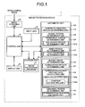
- FIG. 1 is a block diagram illustrating the configuration of an image processing device according to a first embodiment of the invention.
- An image processing device 1 illustrated in FIG. 1 includes a control unit 10 that controls the operation of the entire image processing device 1, an image acquiring unit 20 that acquires image data corresponding to an image captured by a medical observation device, an input unit 30 that receives input signals input from an external device, a display unit 40 that displays various screens, a storage unit 50 that stores the image data acquired by the image acquiring unit 20 and various programs, and a arithmetic unit 100 that executes predetermined image processing on the image data.
- the control unit 10 is implemented by hardware such as a CPU.
- the control unit 10 reads various programs stored in the storage unit 50 to thereby transmit instructions and data to the respective units of the image processing device 1 in accordance with the image data input from the image acquiring unit 20 or an operation signal input from the input unit 30 and control the operation of the entire image processing device 1 in an integrated manner.
- the image acquiring unit 20 is appropriately configured according to an aspect of a system that includes the medical observation device.
- the medical observation device is a capsule endoscope, and a portable recording medium is used in exchanging of image data with the medical observation device
- the image acquiring unit 20 is configured as a reader device that detachably attaches the recording medium and reads image data of the intra-luminal images stored in the recording medium.
- the image acquiring unit 20 is configured as a communication device that is connected to the server and performs data communication with the server to acquire the image data of the intra-luminal images.
- the image acquiring unit 20 may be configured as an interface device or the like that receives image signals from the medical observation device via a cable.
- the input unit 30 is implemented as an input device such as, for example, a keyboard, a mouse, a touch panel, or various switches, and outputs received input signals to the control unit 10.
- the display unit 40 is implemented as a display device such as an LCD or an EL display, and displays various screens including intra-luminal images under control of the control unit 10.
- the storage unit 50 is implemented as various IC memories called a ROM or a RAM such as a rewritable flash memory, an internal hard disk or a hard disk connected to a data communication terminal, or an information storage medium such as a CD-ROM, and a reading device thereof.
- the storage unit 50 stores a program for causing the image processing device 1 to operate and causing the image processing device 1 to execute various functions, and data or the like used during the execution of the program in addition to the image data of the intra-luminal images acquired by the image acquiring unit 20.
- the storage unit 50 stores an image processing program 51 for executing a process of determining a candidate abnormal region from an image using a first predetermined criterion, determining a bubble region, and determining whether the candidate abnormal region is an abnormal region using a second criterion when it is determined that the candidate abnormal region is present within the bubble region.
- the storage unit 50 also stores various determination criteria used during the execution of the image processing program 51.
- the arithmetic unit 100 is implemented by hardware such as a CPU.
- the arithmetic unit 100 performs image processing on the image data corresponding to the intra-luminal image by reading the image processing program 51 and performs various arithmetic processes for determining an abnormal region from an intra-luminal image.
- the arithmetic unit 100 includes a candidate abnormal region determining unit 110 that determines a candidate abnormal region from an image using a first determination criterion, a bubble region determining unit 120 that determines a bubble region from the image, a bubble inside determining unit 130 that determines whether the candidate abnormal region is present inside the bubble region based on the determination result of the bubble region, and an abnormal region determining unit 140 that determines whether the candidate abnormal region is an abnormal region using a second determination criterion different from the first determination criterion when the candidate abnormal region is determined to be present inside the bubble region.
- the bubble region determining unit 120 includes a peripheral region determining unit 121 that determines a region having the features of the peripheral region of the bubble region and an inner region determining unit 122 that determines a region having the features of the inner region of the bubble region.
- the peripheral region determining unit 121 includes an arc-shaped region determining unit 121a that determines an arc-shaped region which is the feature of the peripheral region of the bubble region.
- the inner region determining unit 122 includes a halation region determining unit 122a that determines a halation region which is the feature of the inner region of the bubble region.
- the bubble inside determining unit 130 includes a surrounding region determining unit 131 that determines a surrounding region of the candidate abnormal region and a surrounding region feature data calculating unit 132 that calculates the feature data of the surrounding region based on the determination result of the bubble region in the surrounding region and a region in the vicinity of the surrounding region.
- the surrounding region feature data calculating unit 132 includes an area calculating unit 132a that calculates the area of the bubble region in the surrounding region and the region in the vicinity of the surrounding region. More specifically, the area calculating unit 132a includes a contour extracting unit 132a' that extracts contour pixels of the surrounding region.
- the abnormal region determining unit 140 includes a determination criterion switching unit 141 that switches the determination criterion based on whether the surrounding region of the candidate abnormal region is present inside the bubble region.
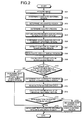
- FIG. 2 is a flowchart illustrating the operation of the image processing device 1.
- step S01 the image acquiring unit 20 acquires a series of intra-luminal images obtained by imaging the lumen of a subject and stores the intra-luminal images in the storage unit 50.
- the arithmetic unit 100 sequentially reads image data corresponding to a processing target image from the storage unit 50.
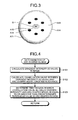
- FIG. 3 is a schematic view illustrating a part of the processing target image read by the arithmetic unit 100 as an example.
- the candidate abnormal region determining unit 110 determines a candidate abnormal region based on the color feature data of the image. More specifically, the candidate abnormal region determining unit 110 calculates a G/R value from the pixel values of the respective pixels that constitute an image and determines a region in which the G/R value is smaller than a predetermined determination criterion value as a candidate abnormal region A10. That is, a region in which red colors are relatively strong (a region in which bleeding or reddening is suspicious) is extracted from the image as the candidate abnormal region A10.
- the peripheral region determining unit 121 determines an arc-shaped region in the image.
- various methods can be used as a method of determining the arc-shaped region, in the first embodiment, a method disclosed in Japanese Laid-open Patent Publication No. 2007-313119 is used.
- FIG. 4 is a flowchart illustrating a detailed process of step S03.
- the arc-shaped region determining unit 121a calculates a gradient intensity (G value) in the image.
- step S102 a correlation value between the gradient intensity (G value) and an arc-shaped model created in advance is calculated.
- a region in which the correlation value between the gradient intensity and the arc-shaped model is equal to or greater than a predetermined threshold value is determined as an arc-shaped region A11 (see FIG. 3 ).
- the processing returns to a main routine.
- step S05 the bubble region determining unit 120 sets the arc-shaped region A11 determined by the peripheral region determining unit 121 and the halation region A12 determined by the inner region determining unit 122 as the bubble region.
- the bubble region includes both the arc-shaped region A11 and the halation region A12.
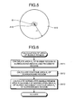
- the surrounding region determining unit 131 determines the surrounding region of the candidate abnormal region A10. More specifically, first, the surrounding region determining unit 131 calculates the gravity center position G of the candidate abnormal region A10 in the image as illustrated in FIG. 5 . Moreover, a region included in a circle of which the origin is located at the gravity center position G and which has a radius of r1 is extracted as a surrounding region A13. The value of the radius r1 may be a predetermined value or may be determined adaptively based on the area of the candidate abnormal region A10.
- step S07 the contour extracting unit 132a' executes a contour tracking process (see Digital Image Processing, CG-ARTS Society, p. 178) to extract a contour (outline) region A14 of the surrounding region A13.
- the area calculating unit 132a calculates the area of the bubble region in the surrounding region A13 and a region in the vicinity of the surrounding region A13. For example, in the case of FIG. 3 , the bubble region (the halation region) A12 is present in the surrounding region A13, and the bubble region (the arc-shaped region) A11 is present so as to overlap the contour region A14 of the surrounding region A13. The area calculating unit 132a calculates the total areas of the bubble regions A11 and A12.
- FIG. 6 is a flowchart illustrating a detailed process of step S08.
- the area S 1 may be divided by the area of the surrounding region A13 instead of the area S 2 of the contour region A14, or the area S 1 may be divided by the sum of the areas of the surrounding region A13 and the contour region A14.
- step S09 the surrounding region feature data calculating unit 132 uses the normalized bubble region area S as the feature data of the surrounding region A13.
- the value itself of the area S 1 of the bubble regions A11 and A12 or the determination result (1 for present and 0 for absent) on the presence of a bubble region in the surrounding region A13 and a region in the vicinity of the surrounding region A13 may be used as the feature data of the surrounding region A13.
- step S10 the bubble inside determining unit 130 determines whether the normalized bubble region area S in the surrounding region A13 of the candidate abnormal region A10 is equal to or greater than a predetermined threshold value (predetermined value).
- predetermined value a predetermined threshold value
- the bubble inside determining unit 130 determines that the candidate abnormal region A10 is inside the bubble region (step S11). This is because the greater the area of the region having the features of the bubble region in the surrounding region A13 and a region in the vicinity of the surrounding region A13 is, the higher the possibility of the candidate abnormal region A10 being an inner region of the bubble region is.
- the candidate abnormal region A10 may be determined to be present inside the bubble region when the area S 1 is equal to or greater than a predetermined value or the bubble region is determined to be present.
- step S12 the determination criterion switching unit 141 reads a determination criterion value created in advance from the storage unit 50.
- the criterion value read at this time is smaller than the criterion value used by the candidate abnormal region determining unit 110 in step S02. That is, the region (the abnormal region) which is determined to fall within the range defined by the criterion value read in step S12 is fewer than the region (the candidate abnormal region) which is determined to fall within the range defined by the criterion value in step S02. In other words, the criterion value read in step S12 is stricter than the criterion value used in step S02.
- the abnormal region determining unit 140 determines whether the candidate abnormal region A10 is an abnormal region based on the determination criterion read in step S12. Specifically, first, in step S13, the abnormal region determining unit 140 calculates a mean value (G/R mean value) of the G/R value of the candidate abnormal region A10. Subsequently, in step S14, the abnormal region determining unit 140 determines whether the calculated G/R mean value is smaller than a determination criterion. When the G/R mean value is determined to be smaller than the determination criterion (Yes in step S14), the abnormal region determining unit 140 determines that the candidate abnormal region A10 is an abnormal region such as a bleeding region or a reddening region (step S15). In this case, a region in which the red colors are stronger than the determination result in step S02 is determined as an abnormal region.
- the abnormal region determining unit 140 determines that the candidate abnormal region A10 is not an abnormal region (step S16).
- step S10 when the normalized bubble region area S is determined to be smaller than a predetermined value (No in step S10), the candidate abnormal region A10 is determined not to be present inside the bubble region (step S17). In this case, the candidate abnormal region A10 is determined as an abnormal region according to the determination in step S02 (step S15).
- a candidate abnormal region which is determined based on a predetermined criterion value from an image, is determined to be present inside a bubble region, it is determined whether the candidate abnormal region is an abnormal region in accordance with a different criterion value such that the corresponding regions are fewer than that obtained when the predetermined criterion value is used. Therefore, it is possible to suppress a mucosal region inside bubbles from being erroneously detected as an abnormal region.
- the G/R value and the luminance value Y have been calculated for each pixel, and the candidate abnormal region and the halation region have been determined.
- an image may be divided into small regions, and the candidate abnormal region and the halation region may be determined for each small region.
- a mean value in each small region of the G/R value and the luminance value Y of the respective pixels is used for the determination process.
- a process of dividing an image based on edge intensity is performed as follows. First, the edge intensity of each of the respective pixels included in a processing target image is calculated. In calculating the edge intensity, a known method such as a differential filtering process using the Sobel filter may be used. Subsequently, the image is divided into multiple edge regions using the ridges of the edge intensities as boundaries. More specifically, an edge intensity image which uses the respective pixels edge intensities as pixel values is created, and a gradient direction of the edge intensities in the pixels of the edge intensity image is acquired. In this case, the gradient direction is set in a direction where the value of the edge intensity decreases. Moreover, pixels having the minimum value which the respective pixels reach when moving along the gradient direction are searched, and the image is divided so that the pixels at the starting point which have reached the adjacent pixels having the minimum value are included in the same region (see WO 2006/080239 A ).
- an existing method such as a watershed algorithm can be also used (see Luc Vincent and Pierre Soille, "Watersheds in digital spaces: An efficient algorithm based on immersion simulations", IEEE Transactions on Pattern Analysis and Machine Intelligence, Vol. 13, No. 6, pp. 583-598, June 1991 ).
- the candidate abnormal region and the halation region are determined based on the feature data of each of the small regions including multiple pixels, it is possible to perform the determination process by reflecting the features of each small region and to improve the computation speed.
- the candidate abnormal region is inside the bubble region using the value obtained by normalizing the total area of the bubble region (the halation region) present in the surrounding region of the candidate abnormal region and the bubble region (the arc-shaped region) near the contour region of the surrounding region by the area of the contour region as the feature data.
- the determination may be performed using the total area of the halation region and the arc-shaped region present in the surrounding region and the region in the vicinity of the surrounding region or a value obtained by normalizing the total area by the area of the surrounding region as the feature data.
- the determination may be performed based on whether a predetermined amount of the arc-shaped region is present in the surrounding region and the region in the vicinity of the surrounding region (for example, the total area of the arc-shaped region or the sum of the lengths of the arcs is equal to or greater than a predetermined threshold value).
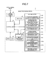
- FIG. 7 is a block diagram illustrating the configuration of an image processing device according to the second embodiment.
- an image processing device 2 according to the second embodiment includes an arithmetic unit 200 which includes a candidate abnormal region determining unit 210 that determines a candidate abnormal region from an image, a bubble region determining unit 220 that determines a bubble region from the image, a bubble inside determining unit 230 that determines whether the candidate abnormal region is present inside the bubble region based on the determination result of the bubble region, and an abnormal region determining unit 240 that determines whether the candidate abnormal region is an abnormal region.
- the configuration of the image processing device 2 other than the arithmetic unit 200 is the same as that illustrated in FIG. 1 .
- the bubble region determining unit 220 includes a peripheral region determining unit 221 that determines a region having the features of the peripheral region of the bubble region and a determination range determining unit 222 that determines a determination range where the bubble region in the image is determined based on the determination result of the candidate abnormal region.
- the peripheral region determining unit 221 includes an arc-shaped region determining unit 221a that determines an arc-shaped region.
- the bubble inside determining unit 230 includes a surrounding region determining unit 231 that determines the surrounding region of the candidate abnormal region and a surrounding region feature determining unit 232 that determines the features of the bubble region in the surrounding region based on the determination result of the bubble region in the surrounding region and the region in the vicinity of the surrounding region.
- the surrounding region feature determining unit 232 includes an arc-shaped bubble region determining unit 232a that determines whether the bubble region in the surrounding region and the region in the vicinity of the surrounding region includes an arc-shaped region and an arc-shaped inner region determining unit 232b that determines whether the surrounding region is an inner region of the arc-shaped region.
- FIG. 8 is a flowchart illustrating the operation of the image processing device according to the second embodiment.
- step S21 the arithmetic unit 200 acquires image data corresponding to a processing target image.
- the detailed process of step S21 is the same as that of step S01 of the first embodiment.
- step S22 the candidate abnormal region determining unit 210 determines a candidate abnormal region based on a color feature data.
- FIG. 9 is a flowchart illustrating a detailed process of determining the candidate abnormal region.
- the candidate abnormal region determining unit 210 calculates the G/R value from the pixel values of the respective pixels that constitute the image.
- the mean value of the G/R values may be calculated for each of the small regions that are obtained by dividing the image.
- step S202 the candidate abnormal region determining unit 210 determines whether each of the calculated G/R values is smaller than a first criterion value set in advance.
- the region is determined as an abnormal region such as a bleeding region or a reddening region (step S203).
- the candidate abnormal region determining unit 210 determines whether the G/R value in the region is smaller than a second criterion value set in advance (second criterion value > first criterion value) (step S204).
- second criterion value > first criterion value the region in which the G/R value is smaller than the second criterion value is detected (Yes in step S204)
- the region is determined as a candidate abnormal region which is likely to be an abnormal region but with low confidence (step S205).
- the region in which the G/R value is equal to or greater than the second criterion value (No in step S204) is determined neither as an abnormal region nor a candidate abnormal region. After that, the processing returns to the main routine.
- the determination range determining unit 222 determines a determination range where the bubble region in the image is determined. Specifically, as illustrated in FIG. 10 , the gravity center position G of a candidate abnormal region A20 determined from the image is calculated, and a region included in a circle of which the origin is located at the gravity center position G and which has a radius of r2 is determined as a determination range A21.
- the value of the radius r2 may be a predetermined value set in advance and may be determined adaptively based on the area of the candidate abnormal region A20.
- step S24 the peripheral region determining unit 221 (the arc-shaped region determining unit 221a) determines an arc-shaped region in the determination range A21.
- a detailed process of a method of determining the arc-shaped region is the same as that described with reference to FIG. 4 in step S03 of the first embodiment.
- FIG. 11 illustrates an example of arc-shaped regions A22 to A26 determined in this way.
- step S25 the bubble region determining unit 220 sets the arc-shaped regions A22 to A26 determined in step S24 as candidate bubble regions.
- step S26 the surrounding region determining unit 231 determines the surrounding region of the candidate abnormal region A20.
- a detailed process of step S26 is the same as that described in step S06 of the first embodiment.
- FIG. 12 illustrates a surrounding region A27 determined in step S26.
- step S27 the arc-shaped bubble region determining unit 232a extracts an arc-shaped candidate bubble region from the candidate bubble regions (arc-shaped regions) A22 to A26 in the surrounding region A27 of the candidate abnormal region A20 and a region in the vicinity of the surrounding region A27 and extracts an arc-shaped inner region.
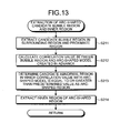
- FIG. 13 is a flowchart illustrating a detailed process of extracting an arc-shaped candidate bubble region and an arc-shaped inner region.
- step S211 the arc-shaped bubble region determining unit 232a extracts a candidate bubble region in the surrounding region A27 of the candidate abnormal region A20 and a region in the vicinity of the surrounding region A27.
- the candidate bubble regions A22 to A24 and A26 are extracted from the candidate bubble regions A22 to A26 set in step S25.
- step S212 the arc-shaped bubble region determining unit 232a calculates a correlation value between the extracted candidate bubble regions A22 to A24 and A26 and an arc-shaped model created in advance.
- a candidate bubble region in which the correlation value with the arc-shaped model is equal to or greater than a predetermined threshold value is determined as an arc-shaped candidate bubble region.
- the candidate bubble regions A22 to A24 are determined as an arc-shaped candidate bubble region.
- the arc-shaped bubble region determining unit 232a extracts an inner region A28 of the candidate bubble regions A22 to A24 determined as an arc-shaped region. After that, the processing returns to the main routine.
- step S28 the arc-shaped inner region determining unit 232b determines whether the arc-shaped inner region A28 extracted in step S27 or the surrounding region A27 of the candidate abnormal region A20 is an inner region of an arc-shaped region.
- the bubble inside determining unit 230 determines that the surrounding region A27 is inside a bubble region (step S29). In this case, in step S30, the abnormal region determining unit 240 determines that the candidate abnormal region A20 in the surrounding region A27 is not an abnormal region.
- the bubble inside determining unit 230 determines that the surrounding region A27 is not inside the bubble region (step S31). In this case, in step S32, the abnormal region determining unit 240 determines that the candidate abnormal region A20 in the surrounding region A27 is an abnormal region.
- a region in which the color feature data is smaller than a first criterion value is determined as an abnormal region.
- a region in which the color feature data is between the first criterion value and the second criterion value and which is likely to be an abnormal region with low confidence it is determined whether the region is an abnormal region using a bubble region. Therefore, it is possible to improve the efficiency of the computation process.
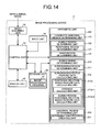
- FIG. 14 is a block diagram illustrating the configuration of an image processing device according to the third embodiment.
- an image processing device 3 according to the third embodiment includes an arithmetic unit 300 which includes the candidate abnormal region determining unit 110, the bubble region determining unit 120, a bubble inside determining unit 310 that determines whether the candidate abnormal region is present inside the bubble region based on the determination result of the bubble region, and an abnormal region determining unit 320 that determines whether the candidate abnormal region is an abnormal region based on the determination result of the bubble inside determining unit 310.
- the configuration and the operation of the candidate abnormal region determining unit 110 and the bubble region determining unit 120 are the same as those described in the first embodiment.
- the configuration of the image processing device 3 other than the arithmetic unit 300 is the same as that illustrated in FIG. 1 .
- the bubble inside determining unit 310 includes a surrounding region determining unit 311 that determines the surrounding region of the candidate abnormal region and a surrounding region feature data calculating unit 312 that calculates a feature data based on the surrounding region.
- the surrounding region feature data calculating unit 312 includes a positional relation-based feature data calculating unit 312a that calculates a feature data based on a positional relation of the bubble region in the surrounding region and the region in the vicinity of the surrounding region.
- the positional relation-based feature data calculating unit 312a includes a distance calculating unit 312a-1 that calculates the distance between bubble regions and a bubble region positional relation-based feature data calculating unit 312a-2 that calculates the feature data based on a positional relation between the arc-shaped region and the halation region.
- the abnormal region determining unit 320 includes a determination criterion creating unit 321 that adaptively creates a determination criterion based on the information on the surrounding region of the candidate abnormal region.
- FIG. 15 is a flowchart illustrating the operation of the image processing device according to the third embodiment.
- FIG. 15 the operations of steps S41 to S46 correspond to the operations of steps S01 to S06 illustrated in FIG. 2 .
- FIG. 16 illustrates a candidate abnormal region A30, an arc-shaped region A31, a halation region A32, and a surrounding region A33 which are determined from the image in steps S41 to S46.
- step S47 the bubble region positional relation-based feature data calculating unit 312a-2 determines whether both the arc-shaped region A31 and the halation region A32 which constitute the bubble region are mixedly present in the surrounding region A33 and the region in the vicinity of the surrounding region A33.
- a halation is generally observed in the inner side of an arc-shaped region that constitutes a portion having an approximately circular shape (including a shape similar to a circle such as an ellipse).
- a region where both a portion determined as the arc-shaped region A31 and a portion determined as the halation region A32 are mixedly present can be determined not to be the bubble region.
- the positional relation-based feature data calculating unit 312a calculates the feature data based on the positional relation in each portion of the bubble region (step S48).
- FIG. 17 is a flowchart illustrating a detailed process of calculating the feature data based on the positional relation in each portion of the bubble region.
- the bubble region positional relation-based feature data calculating unit (hereinafter, simply referred to as a feature data calculating unit) 312a-2 calculates the gravity center position G of the candidate abnormal region A30 in the image.
- the feature data calculating unit 312a-2 calculates the mean distance C from the gravity center position G of the candidate abnormal region A30 to the respective arc-shaped regions A31 present in the surrounding region A33 and the region in the vicinity of the surrounding region A33.
- step S405 the positional relation-based feature data calculating unit 312a sets the difference D calculated in this way as a feature data based on the positional relation in each portion of the bubble region in the surrounding region A33 and the region in the vicinity of the surrounding region A33.
- step S49 the surrounding region feature data calculating unit 312 sets the feature data (the difference D) based on the positional relation in each portion of the bubble region as a feature data in the surrounding region A33.
- step S50 the bubble inside determining unit 310 determines whether the feature data (namely, the difference D) in the surrounding region A33 is equal to or greater than zero.
- the bubble inside determining unit 310 determines that the candidate abnormal region A30 is inside the bubble region (step S51). This is because the fact that the difference D is equal to or greater than zero means that the halation region A32 can be determined to be present inside the arc-shaped region A31.
- step S52 the determination criterion creating unit 321 calculates the mean value (G/R mean value) of the G/R values in portions of the surrounding region A33 other than the candidate abnormal region A30 and the halation region A32.
- the abnormal region determining unit 320 determines whether the candidate abnormal region A30 is an abnormal region using the G/R mean value calculated in step S52 as a determination criterion. Specifically, first, in step S53, the G/R mean value in the respective candidate abnormal regions A30 is calculated. Moreover, in step S54, it is determined whether a difference D AB between the G/R mean value in the surrounding region A33 and the G/R mean value in the candidate abnormal region A30 is equal to or greater than a predetermined threshold value (predetermined value). When the difference D AB is equal to or greater than the predetermined value (Yes in step S54), the abnormal region determining unit 320 determines that the candidate abnormal region A30 is an abnormal region (step S55). On the other hand, when the difference D AB is smaller than the predetermined value (No in step S54), the abnormal region determining unit 320 determines that the candidate abnormal region A30 is not an abnormal region (step S56).
- predetermined value a predetermined threshold value
- step S47 when it is determined in step S47 that both the arc-shaped region and the halation region are mixedly present in the surrounding region A33 and the region in the vicinity of the surrounding region A33 (Yes in step S47), the bubble inside determining unit 310 determines that the candidate abnormal region is not inside the bubble region (step S57). In this case, in step S55, the abnormal region determining unit 320 determines that the candidate abnormal region A30 is an abnormal region.
- the bubble inside determining unit 310 determines that the candidate abnormal region is not inside the bubble region (step S57).
- the third embodiment since it is determined whether the surrounding region of the candidate abnormal region is present inside the bubble region based on the positional relation of the portions that constitute the bubble region, it is possible to improve the detection accuracy of the bubble region.
- the G/R value has been used as the color feature data which is used in determining the candidate abnormal region
- various color feature datas such as the respective RGR values, relative values (B/G values or the like) of the respective RGB values, brightness and color difference calculated by YCbCr conversion, or hue, saturation, and lightness calculated by HSI conversion can be used.
- B/G value when used as the color feature data, it is easy to determine a lesion of a region covered by the bile that is yellow.
- B and G components of an illumination light that illuminates the lumen of a subject are absorbed in a red region by approximately the same amount.
- the candidate abnormal region determined based on the first determination criterion when the candidate abnormal region determined based on the first determination criterion is determined to be present inside the bubble region, it is determined whether the candidate abnormal region is an abnormal region using the second determination criterion different from the first determination criterion.
- the candidate abnormal region is an abnormal region using the second determination criterion different from the first determination criterion.
- the image processing device can be implemented by an image processing program recorded on a recording medium being executed by a computer system such as a personal computer or a workstation.
- the computer system may be used in a state of being connected to an apparatus such as another computer system or a server via a local area network, a wide area network (LAN/WAN) or a public line such as the Internet.
- a computer system such as a personal computer or a workstation.
- the computer system may be used in a state of being connected to an apparatus such as another computer system or a server via a local area network, a wide area network (LAN/WAN) or a public line such as the Internet.
- LAN/WAN wide area network
- public line such as the Internet.
- the image processing device may acquire image data of the intra-luminal images via these networks, output image processing results to various output apparatuses (a viewer, a printer, and the like) connected via these networks, and store the image processing results in a storage device (a recording medium, a reading device thereof, and the like) connected via these networks.
- the invention is not limited to the first to third embodiments and the modification examples thereof, but various inventions can be formed by appropriately combining multiple constituent components disclosed in the respective embodiments and modification examples. For example, some constituent components may be removed from all constituent components illustrated in the respective embodiments and modification examples, and constituent components illustrated in other embodiments and modification examples may be appropriately combined.
Landscapes
- Engineering & Computer Science (AREA)
- Physics & Mathematics (AREA)
- Health & Medical Sciences (AREA)
- Life Sciences & Earth Sciences (AREA)
- Nuclear Medicine, Radiotherapy & Molecular Imaging (AREA)
- General Physics & Mathematics (AREA)
- Medical Informatics (AREA)
- Computer Vision & Pattern Recognition (AREA)
- Radiology & Medical Imaging (AREA)
- General Health & Medical Sciences (AREA)
- Theoretical Computer Science (AREA)
- Surgery (AREA)
- Quality & Reliability (AREA)
- Heart & Thoracic Surgery (AREA)
- Molecular Biology (AREA)
- Animal Behavior & Ethology (AREA)
- Biomedical Technology (AREA)
- Public Health (AREA)
- Veterinary Medicine (AREA)
- Pathology (AREA)
- Optics & Photonics (AREA)
- Biophysics (AREA)
- Signal Processing (AREA)
- Geometry (AREA)
- Endoscopes (AREA)
- Image Analysis (AREA)
Applications Claiming Priority (1)
| Application Number | Priority Date | Filing Date | Title |
|---|---|---|---|
| JP2011229229A JP5980490B2 (ja) | 2011-10-18 | 2011-10-18 | 画像処理装置、画像処理装置の作動方法、及び画像処理プログラム |
Publications (3)
| Publication Number | Publication Date |
|---|---|
| EP2584526A2 true EP2584526A2 (de) | 2013-04-24 |
| EP2584526A3 EP2584526A3 (de) | 2017-05-17 |
| EP2584526B1 EP2584526B1 (de) | 2019-03-20 |
Family
ID=47262942
Family Applications (1)
| Application Number | Title | Priority Date | Filing Date |
|---|---|---|---|
| EP12006600.6A Active EP2584526B1 (de) | 2011-10-18 | 2012-09-20 | Bildverarbeitungsvorrichtung, Bildverarbeitungsverfahren und Bildverarbeitungsprogramm |
Country Status (4)
| Country | Link |
|---|---|
| US (1) | US9299137B2 (de) |
| EP (1) | EP2584526B1 (de) |
| JP (1) | JP5980490B2 (de) |
| CN (1) | CN103218802B (de) |
Families Citing this family (7)
| Publication number | Priority date | Publication date | Assignee | Title |
|---|---|---|---|---|
| JP6097629B2 (ja) * | 2013-04-26 | 2017-03-15 | Hoya株式会社 | 病変評価情報生成装置 |
| JP6552601B2 (ja) | 2015-03-20 | 2019-07-31 | オリンパス株式会社 | 画像処理装置、画像処理装置の作動方法および画像処理プログラム |
| JP6704933B2 (ja) * | 2015-11-26 | 2020-06-03 | オリンパス株式会社 | 画像処理装置、画像処理方法およびプログラム |
| JPWO2017104192A1 (ja) * | 2015-12-17 | 2017-12-14 | オリンパス株式会社 | 医用観察システム |
| CN112766481B (zh) * | 2020-03-13 | 2023-11-24 | 腾讯科技(深圳)有限公司 | 神经网络模型的训练方法、装置及图像检测的方法 |
| JP7602438B2 (ja) * | 2021-07-12 | 2024-12-18 | 富士フイルム株式会社 | 医療画像処理装置及びその作動方法 |
| CN116228758B (zh) * | 2023-05-08 | 2023-07-07 | 深圳市前海誉卓科技有限公司 | 一种用于偏光片生产的内部气泡检测方法 |
Citations (3)
| Publication number | Priority date | Publication date | Assignee | Title |
|---|---|---|---|---|
| JP2005192880A (ja) | 2004-01-08 | 2005-07-21 | Olympus Corp | 画像処理方法 |
| WO2006080239A1 (ja) | 2005-01-31 | 2006-08-03 | Olympus Corporation | 画像処理装置、顕微鏡システム、及び領域特定プログラム |
| JP2007313119A (ja) | 2006-05-26 | 2007-12-06 | Olympus Corp | 画像処理装置及び画像処理プログラム |
Family Cites Families (19)
| Publication number | Priority date | Publication date | Assignee | Title |
|---|---|---|---|---|
| US5815591A (en) * | 1996-07-10 | 1998-09-29 | R2 Technology, Inc. | Method and apparatus for fast detection of spiculated lesions in digital mammograms |
| US6246782B1 (en) * | 1997-06-06 | 2001-06-12 | Lockheed Martin Corporation | System for automated detection of cancerous masses in mammograms |
| US6112112A (en) * | 1998-09-18 | 2000-08-29 | Arch Development Corporation | Method and system for the assessment of tumor extent in magnetic resonance images |
| JP2002330950A (ja) * | 2001-05-11 | 2002-11-19 | Fuji Photo Film Co Ltd | 異常陰影候補検出装置 |
| AUPR509801A0 (en) * | 2001-05-18 | 2001-06-14 | Polartechnics Limited | Boundary finding in dermatological examination |
| AUPR509601A0 (en) * | 2001-05-18 | 2001-06-14 | Polartechnics Limited | Diagnostic feature extraction in dermatological examination |
| US6882743B2 (en) * | 2001-11-29 | 2005-04-19 | Siemens Corporate Research, Inc. | Automated lung nodule segmentation using dynamic programming and EM based classification |
| JP4493386B2 (ja) * | 2003-04-25 | 2010-06-30 | オリンパス株式会社 | 画像表示装置、画像表示方法および画像表示プログラム |
| GB2451367B (en) * | 2004-05-20 | 2009-05-27 | Medicsight Plc | Nodule Detection |
| US20080021502A1 (en) * | 2004-06-21 | 2008-01-24 | The Trustees Of Columbia University In The City Of New York | Systems and methods for automatic symmetry identification and for quantification of asymmetry for analytic, diagnostic and therapeutic purposes |
| US8047993B2 (en) * | 2004-12-08 | 2011-11-01 | Industrial Technology Research Institute | Quantitative non-invasive method for detecting degree of malignancy in tumors and application thereof |
| EP1870020B1 (de) * | 2005-04-13 | 2015-08-05 | Olympus Medical Systems Corp. | Bildverarbeitungsapparat und bildverarbeitungsverfahren |
| US8086002B2 (en) * | 2007-04-27 | 2011-12-27 | Three Palm Software | Algorithms for selecting mass density candidates from digital mammograms |
| JP5004736B2 (ja) * | 2007-09-25 | 2012-08-22 | オリンパス株式会社 | 画像処理装置および画像処理プログラム |
| ATE511683T1 (de) * | 2007-12-28 | 2011-06-15 | Im3D S P A | Klassifikation von markiertem material in einem satz tomografischer bilder der kolorektalregion |
| US8774479B2 (en) * | 2008-02-19 | 2014-07-08 | The Trustees Of The University Of Pennsylvania | System and method for automated segmentation, characterization, and classification of possibly malignant lesions and stratification of malignant tumors |
| JP5374078B2 (ja) * | 2008-06-16 | 2013-12-25 | オリンパス株式会社 | 画像処理装置、画像処理方法および画像処理プログラム |
| JP2010115260A (ja) * | 2008-11-11 | 2010-05-27 | Olympus Corp | 画像処理装置、画像処理プログラムおよび画像処理方法 |
| US9208405B2 (en) * | 2010-08-06 | 2015-12-08 | Sony Corporation | Systems and methods for digital image analysis |
-
2011
- 2011-10-18 JP JP2011229229A patent/JP5980490B2/ja active Active
-
2012
- 2012-09-14 US US13/617,365 patent/US9299137B2/en active Active
- 2012-09-20 EP EP12006600.6A patent/EP2584526B1/de active Active
- 2012-10-16 CN CN201210392607.XA patent/CN103218802B/zh active Active
Patent Citations (3)
| Publication number | Priority date | Publication date | Assignee | Title |
|---|---|---|---|---|
| JP2005192880A (ja) | 2004-01-08 | 2005-07-21 | Olympus Corp | 画像処理方法 |
| WO2006080239A1 (ja) | 2005-01-31 | 2006-08-03 | Olympus Corporation | 画像処理装置、顕微鏡システム、及び領域特定プログラム |
| JP2007313119A (ja) | 2006-05-26 | 2007-12-06 | Olympus Corp | 画像処理装置及び画像処理プログラム |
Non-Patent Citations (1)
| Title |
|---|
| LUC VINCENT; PIERRE SOILLE: "Watersheds in digital spaces: An efficient algorithm based on immersion simulations", IEEE TRANSACTIONS ON PATTERN ANALYSIS AND MACHINE INTELLIGENCE, vol. 13, no. 6, June 1991 (1991-06-01), pages 583 - 598 |
Also Published As
| Publication number | Publication date |
|---|---|
| CN103218802A (zh) | 2013-07-24 |
| EP2584526B1 (de) | 2019-03-20 |
| JP2013085718A (ja) | 2013-05-13 |
| US20130094726A1 (en) | 2013-04-18 |
| JP5980490B2 (ja) | 2016-08-31 |
| US9299137B2 (en) | 2016-03-29 |
| CN103218802B (zh) | 2018-01-16 |
| EP2584526A3 (de) | 2017-05-17 |
Similar Documents
| Publication | Publication Date | Title |
|---|---|---|
| EP2584526A2 (de) | Bildverarbeitungsvorrichtung, Bildverarbeitungsverfahren und Bildverarbeitungsprogramm | |
| JP5117353B2 (ja) | 画像処理装置、画像処理プログラムおよび画像処理方法 | |
| US9639927B2 (en) | Image processing apparatus, image processing method, and computer-readable recording device | |
| US8682048B2 (en) | Image processing device, image processing method, computer-readable recording device | |
| JP5851160B2 (ja) | 画像処理装置、画像処理装置の作動方法、及び画像処理プログラム | |
| JP5424584B2 (ja) | 画像処理装置、画像処理プログラムおよび画像処理装置の作動方法 | |
| KR102176139B1 (ko) | 연속적인 딥 인코더-디코더 네트워크를 이용한 이미지 세그먼테이션 장치 및 그 방법 | |
| US9672612B2 (en) | Image processing device, image processing method, and image processing program for classification of region of interest from intraluminal images based on initial region feature and expansion region feature | |
| EP2557539B1 (de) | Bildverarbeitungsvorrichtung, Bildverarbeitungsverfahren und Bildverarbeitungsprogramm | |
| JP5766986B2 (ja) | 画像処理装置、画像処理方法、及び画像処理プログラム | |
| US9959481B2 (en) | Image processing apparatus, image processing method, and computer-readable recording medium | |
| US8805086B2 (en) | Image processing apparatus, image processing method and computer-readable recording device | |
| US10194783B2 (en) | Image processing apparatus, image processing method, and computer-readable recording medium for determining abnormal region based on extension information indicating state of blood vessel region extending in neighborhood of candidate region | |
| US8811676B2 (en) | Image processing apparatus, image processing method, and computer readable recording device | |
| US20160192832A1 (en) | Image processing apparatus, method of processing image, and image processing program | |
| Lee et al. | Hair segmentation using adaptive threshold from edge and branch length measures | |
| JP2010115260A (ja) | 画像処理装置、画像処理プログラムおよび画像処理方法 |
Legal Events
| Date | Code | Title | Description |
|---|---|---|---|
| PUAI | Public reference made under article 153(3) epc to a published international application that has entered the european phase |
Free format text: ORIGINAL CODE: 0009012 |
|
| AK | Designated contracting states |
Kind code of ref document: A2 Designated state(s): AL AT BE BG CH CY CZ DE DK EE ES FI FR GB GR HR HU IE IS IT LI LT LU LV MC MK MT NL NO PL PT RO RS SE SI SK SM TR |
|
| AX | Request for extension of the european patent |
Extension state: BA ME |
|
| RAP1 | Party data changed (applicant data changed or rights of an application transferred) |
Owner name: OLYMPUS CORPORATION |
|
| RAP1 | Party data changed (applicant data changed or rights of an application transferred) |
Owner name: OLYMPUS CORPORATION |
|
| RAP1 | Party data changed (applicant data changed or rights of an application transferred) |
Owner name: OLYMPUS CORPORATION |
|
| RIN1 | Information on inventor provided before grant (corrected) |
Inventor name: MATSUDA, TAKEHIRO Inventor name: KANDA, YAMATO Inventor name: HIROTA, MASASHI Inventor name: KONO, TAKASHI Inventor name: KITAMURA, MAKOTO |
|
| PUAL | Search report despatched |
Free format text: ORIGINAL CODE: 0009013 |
|
| AK | Designated contracting states |
Kind code of ref document: A3 Designated state(s): AL AT BE BG CH CY CZ DE DK EE ES FI FR GB GR HR HU IE IS IT LI LT LU LV MC MK MT NL NO PL PT RO RS SE SI SK SM TR |
|
| AX | Request for extension of the european patent |
Extension state: BA ME |
|
| RIC1 | Information provided on ipc code assigned before grant |
Ipc: A61B 1/04 20060101ALI20170413BHEP Ipc: G06T 7/00 20170101AFI20170413BHEP |
|
| STAA | Information on the status of an ep patent application or granted ep patent |
Free format text: STATUS: REQUEST FOR EXAMINATION WAS MADE |
|
| 17P | Request for examination filed |
Effective date: 20171117 |
|
| RBV | Designated contracting states (corrected) |
Designated state(s): AL AT BE BG CH CY CZ DE DK EE ES FI FR GB GR HR HU IE IS IT LI LT LU LV MC MK MT NL NO PL PT RO RS SE SI SK SM TR |
|
| STAA | Information on the status of an ep patent application or granted ep patent |
Free format text: STATUS: EXAMINATION IS IN PROGRESS |
|
| 17Q | First examination report despatched |
Effective date: 20180316 |
|
| GRAP | Despatch of communication of intention to grant a patent |
Free format text: ORIGINAL CODE: EPIDOSNIGR1 |
|
| STAA | Information on the status of an ep patent application or granted ep patent |
Free format text: STATUS: GRANT OF PATENT IS INTENDED |
|
| RIC1 | Information provided on ipc code assigned before grant |
Ipc: G06T 7/00 20060101AFI20180921BHEP Ipc: G06T 7/64 20170101ALI20180921BHEP Ipc: A61B 1/04 20060101ALI20180921BHEP Ipc: A61B 1/00 20060101ALI20180921BHEP |
|
| INTG | Intention to grant announced |
Effective date: 20181017 |
|
| GRAS | Grant fee paid |
Free format text: ORIGINAL CODE: EPIDOSNIGR3 |
|
| RIC1 | Information provided on ipc code assigned before grant |
Ipc: G06T 7/64 20170101ALI20180921BHEP Ipc: A61B 1/04 20060101ALI20180921BHEP Ipc: G06T 7/00 20170101AFI20180921BHEP Ipc: A61B 1/00 20060101ALI20180921BHEP |
|
| GRAA | (expected) grant |
Free format text: ORIGINAL CODE: 0009210 |
|
| STAA | Information on the status of an ep patent application or granted ep patent |
Free format text: STATUS: THE PATENT HAS BEEN GRANTED |
|
| AK | Designated contracting states |
Kind code of ref document: B1 Designated state(s): AL AT BE BG CH CY CZ DE DK EE ES FI FR GB GR HR HU IE IS IT LI LT LU LV MC MK MT NL NO PL PT RO RS SE SI SK SM TR |
|
| REG | Reference to a national code |
Ref country code: GB Ref legal event code: FG4D |
|
| REG | Reference to a national code |
Ref country code: CH Ref legal event code: EP |
|
| REG | Reference to a national code |
Ref country code: DE Ref legal event code: R096 Ref document number: 602012057947 Country of ref document: DE |
|
| REG | Reference to a national code |
Ref country code: AT Ref legal event code: REF Ref document number: 1111286 Country of ref document: AT Kind code of ref document: T Effective date: 20190415 |
|
| REG | Reference to a national code |
Ref country code: IE Ref legal event code: FG4D |
|
| REG | Reference to a national code |
Ref country code: NL Ref legal event code: MP Effective date: 20190320 |
|
| PG25 | Lapsed in a contracting state [announced via postgrant information from national office to epo] |
Ref country code: LT Free format text: LAPSE BECAUSE OF FAILURE TO SUBMIT A TRANSLATION OF THE DESCRIPTION OR TO PAY THE FEE WITHIN THE PRESCRIBED TIME-LIMIT Effective date: 20190320 Ref country code: FI Free format text: LAPSE BECAUSE OF FAILURE TO SUBMIT A TRANSLATION OF THE DESCRIPTION OR TO PAY THE FEE WITHIN THE PRESCRIBED TIME-LIMIT Effective date: 20190320 Ref country code: NO Free format text: LAPSE BECAUSE OF FAILURE TO SUBMIT A TRANSLATION OF THE DESCRIPTION OR TO PAY THE FEE WITHIN THE PRESCRIBED TIME-LIMIT Effective date: 20190620 Ref country code: SE Free format text: LAPSE BECAUSE OF FAILURE TO SUBMIT A TRANSLATION OF THE DESCRIPTION OR TO PAY THE FEE WITHIN THE PRESCRIBED TIME-LIMIT Effective date: 20190320 |
|
| REG | Reference to a national code |
Ref country code: LT Ref legal event code: MG4D |
|
| PG25 | Lapsed in a contracting state [announced via postgrant information from national office to epo] |
Ref country code: GR Free format text: LAPSE BECAUSE OF FAILURE TO SUBMIT A TRANSLATION OF THE DESCRIPTION OR TO PAY THE FEE WITHIN THE PRESCRIBED TIME-LIMIT Effective date: 20190621 Ref country code: BG Free format text: LAPSE BECAUSE OF FAILURE TO SUBMIT A TRANSLATION OF THE DESCRIPTION OR TO PAY THE FEE WITHIN THE PRESCRIBED TIME-LIMIT Effective date: 20190620 Ref country code: LV Free format text: LAPSE BECAUSE OF FAILURE TO SUBMIT A TRANSLATION OF THE DESCRIPTION OR TO PAY THE FEE WITHIN THE PRESCRIBED TIME-LIMIT Effective date: 20190320 Ref country code: RS Free format text: LAPSE BECAUSE OF FAILURE TO SUBMIT A TRANSLATION OF THE DESCRIPTION OR TO PAY THE FEE WITHIN THE PRESCRIBED TIME-LIMIT Effective date: 20190320 Ref country code: HR Free format text: LAPSE BECAUSE OF FAILURE TO SUBMIT A TRANSLATION OF THE DESCRIPTION OR TO PAY THE FEE WITHIN THE PRESCRIBED TIME-LIMIT Effective date: 20190320 Ref country code: NL Free format text: LAPSE BECAUSE OF FAILURE TO SUBMIT A TRANSLATION OF THE DESCRIPTION OR TO PAY THE FEE WITHIN THE PRESCRIBED TIME-LIMIT Effective date: 20190320 |
|
| REG | Reference to a national code |
Ref country code: AT Ref legal event code: MK05 Ref document number: 1111286 Country of ref document: AT Kind code of ref document: T Effective date: 20190320 |
|
| PG25 | Lapsed in a contracting state [announced via postgrant information from national office to epo] |
Ref country code: CZ Free format text: LAPSE BECAUSE OF FAILURE TO SUBMIT A TRANSLATION OF THE DESCRIPTION OR TO PAY THE FEE WITHIN THE PRESCRIBED TIME-LIMIT Effective date: 20190320 Ref country code: PT Free format text: LAPSE BECAUSE OF FAILURE TO SUBMIT A TRANSLATION OF THE DESCRIPTION OR TO PAY THE FEE WITHIN THE PRESCRIBED TIME-LIMIT Effective date: 20190720 Ref country code: AL Free format text: LAPSE BECAUSE OF FAILURE TO SUBMIT A TRANSLATION OF THE DESCRIPTION OR TO PAY THE FEE WITHIN THE PRESCRIBED TIME-LIMIT Effective date: 20190320 Ref country code: RO Free format text: LAPSE BECAUSE OF FAILURE TO SUBMIT A TRANSLATION OF THE DESCRIPTION OR TO PAY THE FEE WITHIN THE PRESCRIBED TIME-LIMIT Effective date: 20190320 Ref country code: SK Free format text: LAPSE BECAUSE OF FAILURE TO SUBMIT A TRANSLATION OF THE DESCRIPTION OR TO PAY THE FEE WITHIN THE PRESCRIBED TIME-LIMIT Effective date: 20190320 Ref country code: ES Free format text: LAPSE BECAUSE OF FAILURE TO SUBMIT A TRANSLATION OF THE DESCRIPTION OR TO PAY THE FEE WITHIN THE PRESCRIBED TIME-LIMIT Effective date: 20190320 Ref country code: EE Free format text: LAPSE BECAUSE OF FAILURE TO SUBMIT A TRANSLATION OF THE DESCRIPTION OR TO PAY THE FEE WITHIN THE PRESCRIBED TIME-LIMIT Effective date: 20190320 Ref country code: IT Free format text: LAPSE BECAUSE OF FAILURE TO SUBMIT A TRANSLATION OF THE DESCRIPTION OR TO PAY THE FEE WITHIN THE PRESCRIBED TIME-LIMIT Effective date: 20190320 |
|
| PG25 | Lapsed in a contracting state [announced via postgrant information from national office to epo] |
Ref country code: PL Free format text: LAPSE BECAUSE OF FAILURE TO SUBMIT A TRANSLATION OF THE DESCRIPTION OR TO PAY THE FEE WITHIN THE PRESCRIBED TIME-LIMIT Effective date: 20190320 Ref country code: SM Free format text: LAPSE BECAUSE OF FAILURE TO SUBMIT A TRANSLATION OF THE DESCRIPTION OR TO PAY THE FEE WITHIN THE PRESCRIBED TIME-LIMIT Effective date: 20190320 |
|
| PG25 | Lapsed in a contracting state [announced via postgrant information from national office to epo] |
Ref country code: IS Free format text: LAPSE BECAUSE OF FAILURE TO SUBMIT A TRANSLATION OF THE DESCRIPTION OR TO PAY THE FEE WITHIN THE PRESCRIBED TIME-LIMIT Effective date: 20190720 Ref country code: AT Free format text: LAPSE BECAUSE OF FAILURE TO SUBMIT A TRANSLATION OF THE DESCRIPTION OR TO PAY THE FEE WITHIN THE PRESCRIBED TIME-LIMIT Effective date: 20190320 |
|
| REG | Reference to a national code |
Ref country code: DE Ref legal event code: R097 Ref document number: 602012057947 Country of ref document: DE |
|
| PLBE | No opposition filed within time limit |
Free format text: ORIGINAL CODE: 0009261 |
|
| STAA | Information on the status of an ep patent application or granted ep patent |
Free format text: STATUS: NO OPPOSITION FILED WITHIN TIME LIMIT |
|
| PG25 | Lapsed in a contracting state [announced via postgrant information from national office to epo] |
Ref country code: DK Free format text: LAPSE BECAUSE OF FAILURE TO SUBMIT A TRANSLATION OF THE DESCRIPTION OR TO PAY THE FEE WITHIN THE PRESCRIBED TIME-LIMIT Effective date: 20190320 |
|
| 26N | No opposition filed |
Effective date: 20200102 |
|
| PG25 | Lapsed in a contracting state [announced via postgrant information from national office to epo] |
Ref country code: SI Free format text: LAPSE BECAUSE OF FAILURE TO SUBMIT A TRANSLATION OF THE DESCRIPTION OR TO PAY THE FEE WITHIN THE PRESCRIBED TIME-LIMIT Effective date: 20190320 |
|
| PG25 | Lapsed in a contracting state [announced via postgrant information from national office to epo] |
Ref country code: TR Free format text: LAPSE BECAUSE OF FAILURE TO SUBMIT A TRANSLATION OF THE DESCRIPTION OR TO PAY THE FEE WITHIN THE PRESCRIBED TIME-LIMIT Effective date: 20190320 |
|
| PG25 | Lapsed in a contracting state [announced via postgrant information from national office to epo] |
Ref country code: MC Free format text: LAPSE BECAUSE OF FAILURE TO SUBMIT A TRANSLATION OF THE DESCRIPTION OR TO PAY THE FEE WITHIN THE PRESCRIBED TIME-LIMIT Effective date: 20190320 |
|
| REG | Reference to a national code |
Ref country code: CH Ref legal event code: PL |
|
| PG25 | Lapsed in a contracting state [announced via postgrant information from national office to epo] |
Ref country code: LU Free format text: LAPSE BECAUSE OF NON-PAYMENT OF DUE FEES Effective date: 20190920 Ref country code: IE Free format text: LAPSE BECAUSE OF NON-PAYMENT OF DUE FEES Effective date: 20190920 Ref country code: CH Free format text: LAPSE BECAUSE OF NON-PAYMENT OF DUE FEES Effective date: 20190930 Ref country code: LI Free format text: LAPSE BECAUSE OF NON-PAYMENT OF DUE FEES Effective date: 20190930 |
|
| REG | Reference to a national code |
Ref country code: BE Ref legal event code: MM Effective date: 20190930 |
|
| PG25 | Lapsed in a contracting state [announced via postgrant information from national office to epo] |
Ref country code: BE Free format text: LAPSE BECAUSE OF NON-PAYMENT OF DUE FEES Effective date: 20190930 |
|
| GBPC | Gb: european patent ceased through non-payment of renewal fee |
Effective date: 20190920 |
|
| PG25 | Lapsed in a contracting state [announced via postgrant information from national office to epo] |
Ref country code: FR Free format text: LAPSE BECAUSE OF NON-PAYMENT OF DUE FEES Effective date: 20190930 Ref country code: GB Free format text: LAPSE BECAUSE OF NON-PAYMENT OF DUE FEES Effective date: 20190920 |
|
| PG25 | Lapsed in a contracting state [announced via postgrant information from national office to epo] |
Ref country code: CY Free format text: LAPSE BECAUSE OF FAILURE TO SUBMIT A TRANSLATION OF THE DESCRIPTION OR TO PAY THE FEE WITHIN THE PRESCRIBED TIME-LIMIT Effective date: 20190320 |
|
| PG25 | Lapsed in a contracting state [announced via postgrant information from national office to epo] |
Ref country code: MT Free format text: LAPSE BECAUSE OF FAILURE TO SUBMIT A TRANSLATION OF THE DESCRIPTION OR TO PAY THE FEE WITHIN THE PRESCRIBED TIME-LIMIT Effective date: 20190320 Ref country code: HU Free format text: LAPSE BECAUSE OF FAILURE TO SUBMIT A TRANSLATION OF THE DESCRIPTION OR TO PAY THE FEE WITHIN THE PRESCRIBED TIME-LIMIT; INVALID AB INITIO Effective date: 20120920 |
|
| PG25 | Lapsed in a contracting state [announced via postgrant information from national office to epo] |
Ref country code: MK Free format text: LAPSE BECAUSE OF FAILURE TO SUBMIT A TRANSLATION OF THE DESCRIPTION OR TO PAY THE FEE WITHIN THE PRESCRIBED TIME-LIMIT Effective date: 20190320 |
|
| P01 | Opt-out of the competence of the unified patent court (upc) registered |
Effective date: 20230528 |
|
| PGFP | Annual fee paid to national office [announced via postgrant information from national office to epo] |
Ref country code: DE Payment date: 20250919 Year of fee payment: 14 |