EP2584541B1 - Procédé de contrôle d'accès - Google Patents
Procédé de contrôle d'accès Download PDFInfo
- Publication number
- EP2584541B1 EP2584541B1 EP12450043.0A EP12450043A EP2584541B1 EP 2584541 B1 EP2584541 B1 EP 2584541B1 EP 12450043 A EP12450043 A EP 12450043A EP 2584541 B1 EP2584541 B1 EP 2584541B1
- Authority
- EP
- European Patent Office
- Prior art keywords
- control device
- access control
- electronic key
- data
- transmitted
- Prior art date
- Legal status (The legal status is an assumption and is not a legal conclusion. Google has not performed a legal analysis and makes no representation as to the accuracy of the status listed.)
- Not-in-force
Links
Images

Classifications
-
- G—PHYSICS
- G07—CHECKING-DEVICES
- G07C—TIME OR ATTENDANCE REGISTERS; REGISTERING OR INDICATING THE WORKING OF MACHINES; GENERATING RANDOM NUMBERS; VOTING OR LOTTERY APPARATUS; ARRANGEMENTS, SYSTEMS OR APPARATUS FOR CHECKING NOT PROVIDED FOR ELSEWHERE
- G07C9/00—Individual registration on entry or exit
- G07C9/00174—Electronically operated locks; Circuits therefor; Nonmechanical keys therefor, e.g. passive or active electrical keys or other data carriers without mechanical keys
- G07C9/00309—Electronically operated locks; Circuits therefor; Nonmechanical keys therefor, e.g. passive or active electrical keys or other data carriers without mechanical keys operated with bidirectional data transmission between data carrier and locks
-
- H—ELECTRICITY
- H04—ELECTRIC COMMUNICATION TECHNIQUE
- H04B—TRANSMISSION
- H04B13/00—Transmission systems characterised by the medium used for transmission, not provided for in groups H04B3/00 - H04B11/00
- H04B13/005—Transmission systems in which the medium consists of the human body
-
- G—PHYSICS
- G07—CHECKING-DEVICES
- G07C—TIME OR ATTENDANCE REGISTERS; REGISTERING OR INDICATING THE WORKING OF MACHINES; GENERATING RANDOM NUMBERS; VOTING OR LOTTERY APPARATUS; ARRANGEMENTS, SYSTEMS OR APPARATUS FOR CHECKING NOT PROVIDED FOR ELSEWHERE
- G07C9/00—Individual registration on entry or exit
- G07C9/00174—Electronically operated locks; Circuits therefor; Nonmechanical keys therefor, e.g. passive or active electrical keys or other data carriers without mechanical keys
- G07C9/00944—Details of construction or manufacture
Definitions
- the invention relates to a method for access control, especially in buildings, in which a bidirectional data transmission between an electronic key and an access control device takes place, wherein the data transmission comprises the transmission of identification data from the electronic key to the access control device, wherein the identification data in the access control device for determining the access authorization be evaluated and depending on the established access authorization, a blocking element for selectively enabling or blocking the access is controlled, wherein the data transmission takes place at least partially via a capacitive coupling between the electronic key and the access control device.
- the invention further relates to an apparatus for carrying out this method, comprising an access control device and an electronic key, each having a transmitting / receiving device to allow bidirectional data transmission between the electronic key and the access control device, wherein the electronic key storage for identification data which cooperates with the transmitting / receiving device of the key for transmitting the identification data to the access control device, wherein the access control device has an evaluation circuit for determining the access authorization based on the received identification data and the evaluation circuit cooperates with a blocking element for selectively enabling or disabling the access, wherein the transmitting / receiving device of the electronic key and the access control device each have at least one Koppelka Having capacitive capacitive data transmission module, so that the data transmission can take place at least partially via a capacitive coupling between the electronic key and the access control device.
- the receiving unit of the access control device has at least one capacitive coupling surface, so that upon contact with the access control device or when approaching the access control device by the person closes an AC circuit and an electrical flow through the access control device arises, which can be detected by the receiving unit.
- the result of the capacitive data transmission is that the electronic key itself does not have to be brought into immediate proximity to the recipient of the access control device and no user-controlled activation of the key is required, for example by pressing a button. Rather, it is sufficient if the electronic key is close to the body of the respective user, for example in a trouser pocket, briefcase or the like.
- the data to be transmitted can be modulated here, for example, to a carrier frequency generated by the electronic key.
- the user-friendliness of the access control is thereby substantially increased and it is also ensured that a data transfer takes place only when the person carrying the key approaches the access control device or touches it, so that manipulation possibilities by third parties are virtually eliminated. Furthermore, the fact that a low-power, near-field capacitive field is used, the power consumption of the access control system is extremely low, and in particular the power consumption of the electronic key.
- Electronic keys are understood below to mean different configurations of identification media which have stored an electronic code or identification data, e.g. in the form of cards, key fobs and combinations of mechanical and electronic keys.
- a disadvantage of the capacitive transmission of the data in the course of a blocking operation is that the displacement currents arising in the capacitive coupling due to electrically conductive structures, e.g. in the area of a door, so that the propagation of a signal can not always be precisely controlled. It may therefore be the case, without further precautions, that identification data transmitted by the key are available not only to the access control device of the desired door but also to that of the adjacent door, so that a locking operation may be triggered at the wrong door.
- the WO 2009/152628 A1 shows an access control system with capacitive and HF coupling.
- the invention is therefore based on the object, an access control method or device of the aforementioned To improve the nature of the above-mentioned disadvantages, without losing the benefits of capacitive transmission, such as energy efficiency and the lack of free space propagation.
- the invention provides that a part of the data transmitted between the electronic key and the access control device is transmitted via a capacitive coupling and a part of the data via radio waves.
- the transmission characteristics of the respective methods can be optimally utilized.
- the capacitive coupling the data transmission takes place with the aid of an electric field, while the data transmission takes place in the case of radio waves via an electromagnetic field.
- the fields mentioned have different propagation properties, which are utilized depending on the type of data to be transmitted as well as the amount of data.
- the electric field used for the data transmission by means of the capacitive coupling propagates only a few centimeters wide, while an electromagnetic field occurring in the radio wave transmission has a much greater spread.
- the data transmission rate may also be higher compared to that of the capacitive transmission due to the high carrier frequency.
- the identification data is transmitted from the electronic key to the access control device via a capacitive coupling.
- the transmission and privacy is of particular importance.
- the advantages of the capacitive coupling are exploited, which only works over very short distances, so that a listening or interception of the transmitted data is hardly possible.
- other data that does not serve the immediate identification of a key can be transmitted via radio waves.
- the data transmitted via a return channel from the access control device to the electronic key is less sensitive.
- a further preferred procedure therefore provides that at least part of the data transmitted by the access control device to the electronic key is transmitted via radio waves.
- all data transmitted by the electronic key to the access control device is transmitted via a capacitive coupling and all data transmitted by the access control device to the electronic key are transmitted via radio waves. This reduces the structural complexity both in the access control device and in the electronic key, since the electronic key only requires a capacitively operating transmitter and a receiver for radio wave transmission and the access control device conversely only requires a capacitively operating receiver and a transmitter for radio wave transmission.
- the person carrying the electronic key can be located during the blocking process.
- the "man-in-the-middle" would not have to carry a legitimate key in order to gain access, but could touch the access control device with one hand and the person carrying the valid key with the other hand.
- the location of the person should ensure that the person from whose electronic key the access control device receives data is actually in the immediate vicinity of the access control device.
- the location is preferably in such a way that the access control device emits a presence control signal via radio waves whose range is less than 2m, preferably less than 1m.
- the presence control signal is received only by an electronic key, which is located within the range of the radio signal.
- a further limitation can preferably take place in that the presence control signal is transmitted bundled over at least one directional antenna.
- a message is additionally transmitted from the electronic key to the access control device via a capacitive coupling.
- the data or signal transmission in one direction thus via radio waves and in the other direction via a capacitive coupling, so that the different propagation characteristics of an electric field (capacitive coupling) and an electromagnetic field (radio wave transmission) can be exploited the To determine the position of the electronic key.
- the electronic key is located only in the area where the two propagation fields overlap.
- the presence control signal may be the response to a request message of the key, or the presence control signal may trigger the return of a receipt acknowledgment message. Both are conceivable.
- the procedure is preferably such that the access control device transmits the presence control signal after it has received a request message via a capacitive coupling.
- the electronic key upon receipt of the presence control signal sends back a receipt confirmation message and the access control device releases the further data transmission between the access control device and the electronic key only upon receipt of the receipt confirmation message.
- the acknowledgment message is in this case in particular transmitted back via a capacitive coupling.
- an identifier is transmitted with the request message or the presence control signal which is returned with the returned message.
- a particularly precise location of the electronic key takes place in that the presence control signal is emitted via radio waves whose range is less than 2m, preferably less than 1m.
- the procedure is preferably such that the access control device is associated with a door and that the presence control signal is transmitted and / or received via radio waves directed essentially perpendicular to the door.
- the access control device is associated with a door and that the presence control signal is transmitted and / or received via radio waves directed essentially perpendicular to the door.
- the presence control signal is transmitted and / or received via radio waves directed essentially perpendicular to the door.
- only those electronic keys are detected, which are present in the region of the directed substantially perpendicular to the door radio waves. In this way, a targeted location succeeds in a given surrounding area of a door.
- the data partially transmitted via a capacitive coupling and partly via radio waves can also be used in the case of encrypted transmission of data.
- a preferred procedure in this context provides that the identification data is transmitted via a secure connection via a capacitive coupling and that the required for the establishment of the secure connection exchange of data between the electronic key and the access control device is at least partially via radio waves.
- the transfer of data via a capacitive coupling has, as mentioned above, the advantage that the electronic key itself does not have to be brought into the immediate vicinity of the access control device in order to trigger the data transmission. Rather, it is sufficient that the electronic key is worn on the body or near the body of the person concerned, since the human body can be used as a transmission medium.
- a preferred procedure provides that data transmitted from the electronic key via a capacitive coupling to the access control device is coupled from the electronic key to the person carrying the electronic key and from a body part of the person approaching or touching the coupling electrode of the access control device the access control device are coupled.
- a device of the aforementioned type is developed such that the transmitting / receiving device of the electronic key and the access control device respectively Furthermore, a radio transmission module has, so that the transmitted between the electronic key and the access control device data can be transmitted either via a capacitive coupling and / or radio waves.
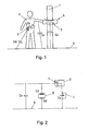
- FIG. 1 a schematic representation of the operation of a working with capacitive access control device
- Fig. 2 a simplified equivalent circuit diagram of the training according to Fig. 1
- Fig. 3 an embodiment in which the data transmission between the electronic key and the access control device takes place both capacitively and via radio waves
- Fig. 4 a flow chart of data transmission.
- Fig. 1 schematically shows a door with a person opening the door and the individual scattering, loss and coupling capacities.
- the door is designated 1 and has an access control device 2 with a trained as a knob actuator 3.
- the person 4 carries an electronic key 5, which may be plugged in a trouser pocket, for example.
- the electronic key 5 in this case generates a capacitive near field with a carrier frequency to which identification data are modulated.
- the capacitive near field is coupled to the body surface of the person 4 and forwarded in the sequence to a receiver of the access control device 2.
- the electronic key 5 has a stray capacitance Cst against the bottom 6.
- At the transition between the electronic key 5 and the person 4 is a coupling capacity Ck too observe.
- loss capacity Cv occurs between the person 4 and the floor 6.
- Cv emulates all the capacitances that result in electrical flows, which do not close from the transmitter via the receiver's receiver capacitor, but pass it and thus contribute nothing to the coupling between receiver and transmitter.
- Cst simulates the capacitance which is available as the sum for the capacitive coupling of the transmitting electrode to ground.
- Ck simulates the capacities which are available as the sum for the capacitive coupling of the person 4 to the second electrode.
- Cz simulates the capacities which are available as the sum for the capacitive coupling of the access control device or its locking cylinder to the ground. It is in the Fig.2 the access control device again denoted by 2 and has a receiving capacitor 7.
- the access control device is again denoted by 2 and the electronic key by 5.
- the access control device 2 comprises a transmitting / receiving device 8 with a control circuit 9, which is responsible for supplying the data to be transmitted either to the radio transmission module 10 or to the capacitive data transmission module 11, which transmits the data via radio waves or via a capacitive coupling.
- the radio transmission module 10 and the capacitive data transmission module 11 each comprise an antenna (not shown).
- the antenna of the radio transmission module 10 is designed, for example, as a directional antenna.
- the antenna of the capacitive data transmission module comprises a coupling capacitor, for example in the form of a capacitor with at least one coupling electrode.
- the data received by the transceiver via a capacitive coupling with the key 5 or via a radio link with the key 5 are supplied to processing means in the form of a microcontroller 12 in which the data is processed.
- a microcontroller 12 In the microcontroller 12, an evaluation circuit 13 is realized, with which it is determined whether there is an access authorization from key 5 received identification data. If the access authorization is checked positively, the microcontroller 12 activates a release element 14 so that a locking member of a locking device (not shown) is released.
- a bidirectional transmission of data takes place between the key 5 and the access control device 2.
- a bidirectional connection is, for example, for the exchange of authentication data in establishing a secure connection between the key 5 and the access control device 2 and for the exchange of status data and test data od.
- the data provided for the transmission from the access control device 2 to the key 2 are stored in the Microcontroller 12 is generated and processed and fed to the transmitting / receiving device 8.
- a matching circuit 15 embodied in the microcontroller 12 is responsible for adapting the data for transmission via the radio transmission module 10 or the capacitive data transmission module 11, which may be necessary, for example, because of the different transmission protocols depending on the module.
- the signal strength can also be adapted, wherein the matching circuit can in principle also be provided in the transmitting / receiving device 8.
- the electronic key 5 also has processing means in the form of a microcontroller 16 and a transmitting / receiving device 17 connected to the microcontroller 16 with a radio transmission module 18 and a capacitive data transmission module 19.
- the control circuit 20 is responsible for supplying the data to be transmitted either to the radio transmission module 18 or to the capacitive data transmission module 19, depending on the specification.
- the microcontroller comprises a memory 21 for identification data.
- the data communication specified in the following example can take place.
- the access control device eg integrated in the fitting
- an electronic key eg a ID medium
- a communication is actively established by both parties. If the transmission is purely capacitive, it is not absolutely necessary to use a frequency from an ISM frequency band, since with this type of transmission no electromagnetic radiation takes place into the room.
- Fig. 4 shows the sequence of a data transfer.
- the fitting sends a request message at the beginning to determine if the identification medium is located nearby and is ready for use. As soon as the identification medium detects this signal successfully, it sends an acknowledge signal (ACK) back to the fitting.
- ACK acknowledge signal
- both the fitting and the identification medium have successfully recognized that the respective call partner is authentic or valid. Incomplete data, too long waiting time for the response and invalid data immediately lead to a communication abort.
- an 8-byte session key can be generated on both sides. These are set over a fixed Calculation algorithm generated from RndNrI and RndNrB. By using the generated random numbers it is ensured that with each authentication a different key is used, which excludes replay attacks and hack attempts to calculate the secret keys SI and SB very elaborate.
- the session key is used to encrypt data in encrypted form (see Fig. 4 "Session"). These are necessary to read or write information such as battery status, keys, etc. and can be expanded as required.
- a session is terminated by an end-of-session signal (EOS). A disconnect, too long computation times, and too many retries will automatically result in termination of the session. After a termination of the session, as well as an EOS signal as well as an error, the session key must be recreated.
- EOS end-of-session signal
- the key-to-key communication channel in this example uses radio waves as the carrier medium, whereas the key-to-key communication channel uses the near-field capacitive field.
- the communication from the fitting to the key takes place via radio waves, the communication from the key to the fitting takes place via a capacitive coupling.
- the identification medium sends when approaching and / or touching the identification data in a package to the fitting. After receipt of the data, the fitting checks with the sent and calculated checksum the correctness of the data packet. If the data agree (no transmission errors), the fitting sends its response data (battery status, event lists, ...) to the ID medium via radio. The identification medium responds capacitively with an OK if the data was received correctly. Otherwise, the identification medium can request the retransmission of the data when fitting.
- the Ident Medium sends its data to the hardware in several consecutive short packets backed up by a checksum or CRC. If one of these short packages is corrupted, the fitting will request its re-shipment. Thus, the total transmission time is extended in the case of individual disturbances only by the repetition period of the one disturbed short packet, that is insignificant, which compared to the example case 1 (all key data must be retransmitted) is more efficient.
- the key-to-key communication takes place via capacitive coupling, while the key-to-key communication can take place both via radio waves and via capacitive coupling.
- the data is sent and received similarly to the cases 1 and 2 described above.
- the identification medium gets from the fitting a short temporary valid identifier, which is only shortly before the touch or capacitive returned to the fitting back on contact. Since the signal strength in the capacitive transmission at fast contact, as well as very much in contact increases sharply, it can be detected, which person touches the fitting. All data is transmitted encrypted despite the short range.
- a plurality of ident media in the transmission / reception area) can be read out beforehand by radio, and it is then determined on contact who operates the door.
Landscapes
- Engineering & Computer Science (AREA)
- Computer Networks & Wireless Communication (AREA)
- Signal Processing (AREA)
- Physics & Mathematics (AREA)
- General Physics & Mathematics (AREA)
- Lock And Its Accessories (AREA)
Claims (24)
- Procédé de contrôle d'accès, en particulier dans des immeubles, dans lequel il se produit une transmission de données bidirectionnelle entre une clé électronique et un dispositif de contrôle d'accès, la transmission de données comprenant la transmission de données d'identification de la clé électronique au dispositif de contrôle d'accès, les données d'identification étant analysées dans le dispositif de contrôle d'accès pour vérifier l'autorisation d'accès et, d'après la vérification de l'autorisation d'accès, un organe de blocage est commandé pour débloquer ou bloquer l'accès, au choix, la transmission de données s'effectuant au moins en partie par l'intermédiaire d'un couplage capacitif entre la clé électronique et le dispositif de contrôle d'accès, une partie des données transmises entre la clé électronique (5) et le dispositif de contrôle d'accès (2) étant transmise par l'intermédiaire d'un couplage capacitif et une partie des données étant transmise par l'intermédiaire d'ondes radio, caractérisé en ce que la transmission de données bidirectionnelle comprend l'émission d'un signal de contrôle de présence par le dispositif de contrôle d'accès (2), le signal de contrôle de présence étant émis par l'intermédiaire d'ondes radio dont la portée est inférieure à 2 m, de préférence inférieure à 1 m.
- Procédé selon la revendication 1, caractérisé en ce que les données d'identification sont transmises de la clé électronique (5) au dispositif de contrôle d'accès (2) par l'intermédiaire d'un couplage capacitif.
- Procédé selon la revendication 1 ou 2, caractérisé en ce qu'au moins une partie des données transmises du dispositif de contrôle d'accès (2) à la clé électronique (5) est transmise par l'intermédiaire d'ondes radio.
- Procédé selon la revendication 1, 2 ou 3, caractérisé en ce que toutes les données transmises de la clé électronique (5) au dispositif de contrôle d'accès (2) sont transmises par l'intermédiaire d'un couplage capacitif et toutes les données transmises du dispositif de contrôle d'accès (2) à la clé électronique (5) sont transmises par l'intermédiaire d'ondes radio.
- Procédé selon l'une des revendications 1 à 4, caractérisé en ce que le signal de contrôle de présence est émis par l'intermédiaire d'au moins une antenne directionnelle, sous forme de faisceau.
- Procédé selon l'une des revendications 1 à 5, caractérisé en ce que le dispositif de contrôle d'accès (2) émet le signal de contrôle de présence après avoir reçu un message d'interrogation par l'intermédiaire d'un couplage capacitif.
- Procédé selon l'une des revendications 1 à 6, caractérisé en ce que, lors de la réception du signal de contrôle de présence, la clé électronique (5) transmet en retour un message d'accusé de réception et le dispositif de contrôle d'accès (2) ne débloque la poursuite de la transmission de données entre le dispositif de contrôle d'accès (2) et la clé électronique (5) qu'à réception du message d'accusé de réception.
- Procédé selon la revendication 7, caractérisé en ce que le message d'accusé de réception est transmis en retour par l'intermédiaire d'un couplage capacitif.
- Procédé selon l'une des revendications 1 à 8, caractérisé en ce qu'avec le message d'interrogation ou avec le signal de contrôle de présence, est transmis un indicatif qui est retourné avec le message transmis en retour.
- Procédé selon l'une des revendications 1 à 9, caractérisé en ce que la transmission de données bidirectionnelle entre la clé électronique (5) et le dispositif de contrôle d'accès (2) comprend les étapes suivantes :- transmission des données d'identification de la clé électronique (5) au dispositif de contrôle d'accès (2) par l'intermédiaire d'un couplage capacitif,- vérification du fait que la clé électronique (5) est présente dans une zone locale prédéterminée située à proximité du dispositif de contrôle d'accès (2), par le fait qu'un signal de contrôle de présence est émis par le dispositif de contrôle d'accès (2) par l'intermédiaire d'ondes radio dirigées et qu'en cas de réception du signal de contrôle de présence par la clé électronique (5), un accusé de réception est transmis de la clé électronique (5) au dispositif de contrôle d'accès (2).
- Procédé selon l'une des revendications 1 à 10, caractérisé en ce que le dispositif de contrôle d'accès (2) est affecté à une porte (1) et en ce que le signal de contrôle de présence est émis et/ou reçu par l'intermédiaire d'ondes radio dirigées sensiblement perpendiculairement à la porte (1).
- Procédé selon l'une des revendications 1 à 11, caractérisé en ce que les données d'identification sont transmises par une liaison sécurisée par l'intermédiaire d'un couplage capacitif et en ce que l'échange de données entre la clé électronique (5) et le dispositif de contrôle d'accès (2) qui est nécessaire pour l'établissement de la liaison sécurisée, s'effectue au moins en partie par l'intermédiaire d'ondes radio.
- Procédé selon l'une des revendications 1 à 12, caractérisé en ce que des données transmises de la clé électronique (5) au dispositif de contrôle d'accès (2) par l'intermédiaire d'un couplage capacitif sont injectées dans la personne (4) qui porte la clé électronique (5) et sont injectées dans le dispositif de contrôle d'accès (2) par une partie du corps de la personne (4) qui s'approche d'une électrode de couplage du dispositif de contrôle d'accès (2) ou la touche.
- Dispositif pour la mise en oeuvre du procédé selon l'une des revendications 1 à 13, comprenant un dispositif de contrôle d'accès (2) et une clé électronique (5) qui présentent chacun un dispositif d'émission/réception (8), pour permettre une transmission de données bidirectionnelle entre la clé électronique (5) et le dispositif de contrôle d'accès (2), la clé électronique (5) présentant une mémoire (21) pour des données d'identification, qui coopère avec le dispositif d'émission/réception (8) de la clé (5) pour assurer la transmission des données d'identification au dispositif de contrôle d'accès (2), le dispositif de contrôle d'accès (2) présentant un circuit d'évaluation (13) destiné à constater l'autorisation d'accès sur la base des données d'identification reçues et le circuit d'évaluation (13) coopérant avec un organe de blocage pour l'exécution sélective du déblocage ou du blocage de l'accès, le dispositif d'émission/réception (8) de la clé électronique (5) et celui du dispositif de contrôle d'accès (2) présentant chacun un module de transmission de données (11) de type capacitif qui présente au moins une capacité de couplage, de sorte que la transmission de données entre la clé électronique (5) et le dispositif de contrôle d'accès (2) peut s'effectuer au moins en partie par l'intermédiaire d'un couplage capacitif, le dispositif d'émission/réception (8) de la clé électronique (5) et celui du dispositif de contrôle d'accès (2) présentant en outre chacun un module de transmission radio (10), de sorte que les données transmises entre la clé électronique (5) et le dispositif de contrôle d'accès (2) peuvent être transmises au choix par l'intermédiaire d'un couplage capacitif et/ou par l'intermédiaire d'ondes radio, caractérisé en ce que le circuit de commande (20) du dispositif de contrôle d'accès (2) est agencé de telle sorte qu'un signal de contrôle de présence est émis par le dispositif de contrôle d'accès (2) par l'intermédiaire d'ondes radio dont la portée est inférieure à 2 m, de préférence inférieure à 1 m.
- Dispositif selon la revendication 14, caractérisé en ce que le dispositif d'émission/réception (8) de la clé électronique (5) et celui du dispositif de contrôle d'accès (2) présentent chacun un circuit de commande qui est agencé pour recevoir ou émettre les données en fonction des informations de commande, soit par l'intermédiaire du module de transmission radio (10), soit par l'intermédiaire du module de transmission de données capacitif (11), soit encore par l'intermédiaire des deux modules.
- Dispositif selon la revendication 15, caractérisé en ce que le circuit de commande (20) est agencé de telle sorte que les données d'identification sont transmises par la clé électronique (5) au dispositif de contrôle d'accès (2) par l'intermédiaire du module de transmission de données capacitif (11).
- Dispositif selon la revendication 15 ou 16, caractérisé en ce que le circuit de commande (20) est agencé de telle sorte qu'au moins une partie des données transmises du dispositif de contrôle d'accès (2) à la clé électronique (5) sont transmises par l'intermédiaire du module de transmission radio (10).
- Dispositif selon la revendication 15, 16 ou 17, caractérisé en ce que le circuit de commande (20) est conçu de telle sorte que toutes les données transmises du dispositif de contrôle d'accès (2) à la clé électronique (5) sont transmises par l'intermédiaire du module de transmission radio (10) et que toutes les données transmises de la clé électronique (5) au dispositif de contrôle d'accès (2) sont transmises par l'intermédiaire du module de transmission de données capacitif (11).
- Dispositif selon l'une des revendications 14 à 18, caractérisé en ce que le module de transmission radio (10) comprend des moyens de réglage servant à régler la puissance d'émission.
- Dispositif selon l'une des revendications 14 à 19, caractérisé en ce que le module de transmission radio (10) présente une puissance d'émission telle que la portée des ondes radio émises soit inférieure à 2 m, de préférence inférieure à 1 m.
- Dispositif selon l'une des revendications 14 à 20, caractérisé en ce que le module de transmission radio (10) est constitué par un émetteur directif.
- Dispositif selon la revendication 21, caractérisé en ce que le dispositif de contrôle d'accès (2) est affecté à une porte (1) et que l'antenne directive de l'émetteur directif est conçue pour émettre/recevoir les ondes radio dans une direction sensiblement perpendiculaire à la porte (1).
- Dispositif selon l'une des revendications 14 à 22, caractérisé en ce qu'il est prévu des moyens pour établir une liaison sécurisée entre la clé électronique (5) et le dispositif de contrôle d'accès (2) et en ce que les circuits de commande de la clé électronique (5) et du dispositif de contrôle d'accès (2) sont conçus de telle sorte que les données d'identification sont transmises par l'intermédiaire de la liaison sécurisée et par l'intermédiaire du module de transmission de données capacitif (11, 19) et que l'échange de données entre la clé électronique (5) et le dispositif de contrôle d'accès (2) qui est nécessaire pour l'établissement de la liaison sécurisée s'effectue par l'intermédiaire du module de transmission radio (10, 18).
- Dispositif selon l'une des revendications 14 23, caractérisé en ce que les dispositifs d'émission/réception (8) présentent chacun un circuit d'adaptation du signal servant à adapter le signal à transmettre en fonction du besoin pour la transmission par ondes radio ou pour la transmission capacitive.
Applications Claiming Priority (1)
| Application Number | Priority Date | Filing Date | Title |
|---|---|---|---|
| AT15252011A AT512075A1 (de) | 2011-10-18 | 2011-10-18 | Verfahren zur zutrittskontrolle |
Publications (2)
| Publication Number | Publication Date |
|---|---|
| EP2584541A1 EP2584541A1 (fr) | 2013-04-24 |
| EP2584541B1 true EP2584541B1 (fr) | 2015-08-05 |
Family
ID=47137651
Family Applications (1)
| Application Number | Title | Priority Date | Filing Date |
|---|---|---|---|
| EP12450043.0A Not-in-force EP2584541B1 (fr) | 2011-10-18 | 2012-10-18 | Procédé de contrôle d'accès |
Country Status (3)
| Country | Link |
|---|---|
| EP (1) | EP2584541B1 (fr) |
| AT (1) | AT512075A1 (fr) |
| ES (1) | ES2547101T3 (fr) |
Families Citing this family (4)
| Publication number | Priority date | Publication date | Assignee | Title |
|---|---|---|---|---|
| US20150044969A1 (en) * | 2013-08-09 | 2015-02-12 | Microchip Technology Incorporated | Wireless Transmission System and Method |
| DE102014011753B4 (de) * | 2014-08-08 | 2022-04-28 | Testo Ag | Verfahren zur Übertragung eines Signals, Verwendung eines menschlichen Körpers zu einer Bildung eines Signalübertragungswegs und Signalübertragungsvorrichtung |
| AT516288B1 (de) * | 2014-09-19 | 2024-09-15 | Evva Sicherheitstechnologie | Verfahren und Vorrichtung zum Verwalten von Zutrittsberechtigungen |
| CN109754505B (zh) * | 2018-12-19 | 2022-07-12 | 广州羊城通有限公司 | 一种基于ic卡的开锁方法及装置 |
Family Cites Families (6)
| Publication number | Priority date | Publication date | Assignee | Title |
|---|---|---|---|---|
| DE19902983A1 (de) * | 1998-12-21 | 2000-07-06 | Mannesmann Vdo Ag | Verfahren und System zur Datenübertragung bei einer Sicherheitseinrichtung eines Kraftfahrzeuges |
| EP1024626A1 (fr) * | 1999-01-27 | 2000-08-02 | International Business Machines Corporation | Méthode, appareil, et système de communication pour l'échange d'information dans des environnements répandus |
| DE10132031A1 (de) * | 2001-07-03 | 2003-01-23 | Texas Instruments Deutschland | Verfahren zur Ermöglichung des authentifizierten Zugangs eines Individuums zu einem geschützten Bereich und Sicherheitssystem zur Durchführung des Verfahrens |
| DE10331440A1 (de) * | 2003-07-10 | 2005-02-17 | Huf Hülsbeck & Fürst Gmbh & Co. Kg | Elektronische Zugangskontrollvorrichtung, sowie Verfahren zur Zugangskontrolle |
| TW200727609A (en) * | 2005-09-27 | 2007-07-16 | Kaba Ag | A method and system for the transmission of identification signals |
| EP2304693B1 (fr) * | 2008-06-18 | 2016-08-31 | Kaba AG | Procédé et système de contrôle d' accès |
-
2011
- 2011-10-18 AT AT15252011A patent/AT512075A1/de not_active Application Discontinuation
-
2012
- 2012-10-18 EP EP12450043.0A patent/EP2584541B1/fr not_active Not-in-force
- 2012-10-18 ES ES12450043.0T patent/ES2547101T3/es active Active
Also Published As
| Publication number | Publication date |
|---|---|
| AT512075A1 (de) | 2013-05-15 |
| ES2547101T3 (es) | 2015-10-01 |
| EP2584541A1 (fr) | 2013-04-24 |
Similar Documents
| Publication | Publication Date | Title |
|---|---|---|
| AT506344B1 (de) | Verfahren und vorrichtung zur steuerung der zutrittskontrolle | |
| AT513461B1 (de) | Verfahren zur Zutrittskontrolle | |
| CH709804B1 (de) | Elektronische Zugangskontrollvorrichtung und Zugangskontrollverfahren. | |
| EP3031676A2 (fr) | Dispositif pour un systeme de securite d'un vehicule | |
| EP2584541A1 (fr) | Procédé de contrôle d'accès | |
| EP2624223B1 (fr) | Procédé et dispositif de contrôle d'accès | |
| EP2304693B1 (fr) | Procédé et système de contrôle d' accès | |
| EP1317824A2 (fr) | Procede et systeme de controle d'acces | |
| CH711351A1 (de) | Elektronische Zugangskontrollvorrichtung und Zugangskontrollverfahren. | |
| EP2584540A2 (fr) | Procédé de contrôle d'accès | |
| DE102007022944A1 (de) | Kontaktloser portabler Datenträger | |
| DE102008007842B3 (de) | Synchronisation der Kommunikation zwischen Identifikationsgeber und Fahrzeugstation einer Zugangsvorrichtung | |
| EP2469481A1 (fr) | Système de sécurisation et procédé de sécurisation | |
| EP2859536B1 (fr) | Procédé de preuve sécurisée par cryptographie de la présence d'un jeton d'identité dans la zone d'un capteur d'identité, ainsi que capteur d'identité pour un tel procédé | |
| EP2871616B1 (fr) | Procédé et dispositif de contrôle d'accès | |
| DE19958145C1 (de) | Vorrichtung zur Aktivierung und/oder Deaktivierung einer Sicherheitseinrichtung | |
| AT504633B1 (de) | Verfahren zur authentifizierung eines mobilfunkendgerätes | |
| EP2063380A2 (fr) | Appareil de communication destiné à la transmission de données sans contact par l'intermédiaire d'un champ de proximité | |
| EP3739554A1 (fr) | Procédé de fonctionnement d'un système de contrôle d'accès ainsi que système de contrôle d'accès | |
| EP3023945B1 (fr) | Procédé et dispositif de détermination de la distance pour un contrôle d'accès | |
| DE10206128B4 (de) | Elektrisches Handwerkzeug | |
| AT13608U1 (de) | Verfahren und Vorrichtung zur Steuerung der Zutrittskontrolle | |
| EP3444150B1 (fr) | Sécurisation d'une communication radio pour systèmes d'accès au véhicule | |
| EP3529904A1 (fr) | Système de communication destiné à la communication sans fil et procédé de commande d'un tel système de communication | |
| WO2018202569A1 (fr) | Chiffrement de balises |
Legal Events
| Date | Code | Title | Description |
|---|---|---|---|
| PUAI | Public reference made under article 153(3) epc to a published international application that has entered the european phase |
Free format text: ORIGINAL CODE: 0009012 |
|
| AK | Designated contracting states |
Kind code of ref document: A1 Designated state(s): AL AT BE BG CH CY CZ DE DK EE ES FI FR GB GR HR HU IE IS IT LI LT LU LV MC MK MT NL NO PL PT RO RS SE SI SK SM TR |
|
| AX | Request for extension of the european patent |
Extension state: BA ME |
|
| 17P | Request for examination filed |
Effective date: 20131024 |
|
| RBV | Designated contracting states (corrected) |
Designated state(s): AL AT BE BG CH CY CZ DE DK EE ES FI FR GB GR HR HU IE IS IT LI LT LU LV MC MK MT NL NO PL PT RO RS SE SI SK SM TR |
|
| 17Q | First examination report despatched |
Effective date: 20140612 |
|
| GRAP | Despatch of communication of intention to grant a patent |
Free format text: ORIGINAL CODE: EPIDOSNIGR1 |
|
| INTG | Intention to grant announced |
Effective date: 20150309 |
|
| GRAS | Grant fee paid |
Free format text: ORIGINAL CODE: EPIDOSNIGR3 |
|
| GRAA | (expected) grant |
Free format text: ORIGINAL CODE: 0009210 |
|
| AK | Designated contracting states |
Kind code of ref document: B1 Designated state(s): AL AT BE BG CH CY CZ DE DK EE ES FI FR GB GR HR HU IE IS IT LI LT LU LV MC MK MT NL NO PL PT RO RS SE SI SK SM TR |
|
| REG | Reference to a national code |
Ref country code: GB Ref legal event code: FG4D Free format text: NOT ENGLISH |
|
| REG | Reference to a national code |
Ref country code: CH Ref legal event code: EP |
|
| REG | Reference to a national code |
Ref country code: AT Ref legal event code: REF Ref document number: 741089 Country of ref document: AT Kind code of ref document: T Effective date: 20150815 |
|
| REG | Reference to a national code |
Ref country code: IE Ref legal event code: FG4D Free format text: LANGUAGE OF EP DOCUMENT: GERMAN |
|
| REG | Reference to a national code |
Ref country code: CH Ref legal event code: NV Representative=s name: OK PAT AG PATENTE MARKEN LIZENZEN, CH |
|
| REG | Reference to a national code |
Ref country code: DE Ref legal event code: R096 Ref document number: 502012004016 Country of ref document: DE |
|
| REG | Reference to a national code |
Ref country code: ES Ref legal event code: FG2A Ref document number: 2547101 Country of ref document: ES Kind code of ref document: T3 Effective date: 20151001 |
|
| REG | Reference to a national code |
Ref country code: FR Ref legal event code: PLFP Year of fee payment: 4 |
|
| REG | Reference to a national code |
Ref country code: SE Ref legal event code: TRGR |
|
| REG | Reference to a national code |
Ref country code: NL Ref legal event code: FP |
|
| REG | Reference to a national code |
Ref country code: LT Ref legal event code: MG4D |
|
| PG25 | Lapsed in a contracting state [announced via postgrant information from national office to epo] |
Ref country code: NO Free format text: LAPSE BECAUSE OF FAILURE TO SUBMIT A TRANSLATION OF THE DESCRIPTION OR TO PAY THE FEE WITHIN THE PRESCRIBED TIME-LIMIT Effective date: 20151105 Ref country code: LT Free format text: LAPSE BECAUSE OF FAILURE TO SUBMIT A TRANSLATION OF THE DESCRIPTION OR TO PAY THE FEE WITHIN THE PRESCRIBED TIME-LIMIT Effective date: 20150805 Ref country code: GR Free format text: LAPSE BECAUSE OF FAILURE TO SUBMIT A TRANSLATION OF THE DESCRIPTION OR TO PAY THE FEE WITHIN THE PRESCRIBED TIME-LIMIT Effective date: 20151106 Ref country code: LV Free format text: LAPSE BECAUSE OF FAILURE TO SUBMIT A TRANSLATION OF THE DESCRIPTION OR TO PAY THE FEE WITHIN THE PRESCRIBED TIME-LIMIT Effective date: 20150805 Ref country code: FI Free format text: LAPSE BECAUSE OF FAILURE TO SUBMIT A TRANSLATION OF THE DESCRIPTION OR TO PAY THE FEE WITHIN THE PRESCRIBED TIME-LIMIT Effective date: 20150805 |
|
| PG25 | Lapsed in a contracting state [announced via postgrant information from national office to epo] |
Ref country code: IS Free format text: LAPSE BECAUSE OF FAILURE TO SUBMIT A TRANSLATION OF THE DESCRIPTION OR TO PAY THE FEE WITHIN THE PRESCRIBED TIME-LIMIT Effective date: 20151205 Ref country code: PT Free format text: LAPSE BECAUSE OF FAILURE TO SUBMIT A TRANSLATION OF THE DESCRIPTION OR TO PAY THE FEE WITHIN THE PRESCRIBED TIME-LIMIT Effective date: 20151207 Ref country code: HR Free format text: LAPSE BECAUSE OF FAILURE TO SUBMIT A TRANSLATION OF THE DESCRIPTION OR TO PAY THE FEE WITHIN THE PRESCRIBED TIME-LIMIT Effective date: 20150805 Ref country code: PL Free format text: LAPSE BECAUSE OF FAILURE TO SUBMIT A TRANSLATION OF THE DESCRIPTION OR TO PAY THE FEE WITHIN THE PRESCRIBED TIME-LIMIT Effective date: 20150805 Ref country code: RS Free format text: LAPSE BECAUSE OF FAILURE TO SUBMIT A TRANSLATION OF THE DESCRIPTION OR TO PAY THE FEE WITHIN THE PRESCRIBED TIME-LIMIT Effective date: 20150805 |
|
| PG25 | Lapsed in a contracting state [announced via postgrant information from national office to epo] |
Ref country code: IT Free format text: LAPSE BECAUSE OF FAILURE TO SUBMIT A TRANSLATION OF THE DESCRIPTION OR TO PAY THE FEE WITHIN THE PRESCRIBED TIME-LIMIT Effective date: 20150805 Ref country code: EE Free format text: LAPSE BECAUSE OF FAILURE TO SUBMIT A TRANSLATION OF THE DESCRIPTION OR TO PAY THE FEE WITHIN THE PRESCRIBED TIME-LIMIT Effective date: 20150805 Ref country code: DK Free format text: LAPSE BECAUSE OF FAILURE TO SUBMIT A TRANSLATION OF THE DESCRIPTION OR TO PAY THE FEE WITHIN THE PRESCRIBED TIME-LIMIT Effective date: 20150805 Ref country code: SK Free format text: LAPSE BECAUSE OF FAILURE TO SUBMIT A TRANSLATION OF THE DESCRIPTION OR TO PAY THE FEE WITHIN THE PRESCRIBED TIME-LIMIT Effective date: 20150805 Ref country code: CZ Free format text: LAPSE BECAUSE OF FAILURE TO SUBMIT A TRANSLATION OF THE DESCRIPTION OR TO PAY THE FEE WITHIN THE PRESCRIBED TIME-LIMIT Effective date: 20150805 |
|
| REG | Reference to a national code |
Ref country code: DE Ref legal event code: R097 Ref document number: 502012004016 Country of ref document: DE |
|
| PG25 | Lapsed in a contracting state [announced via postgrant information from national office to epo] |
Ref country code: LU Free format text: LAPSE BECAUSE OF FAILURE TO SUBMIT A TRANSLATION OF THE DESCRIPTION OR TO PAY THE FEE WITHIN THE PRESCRIBED TIME-LIMIT Effective date: 20151018 Ref country code: RO Free format text: LAPSE BECAUSE OF FAILURE TO SUBMIT A TRANSLATION OF THE DESCRIPTION OR TO PAY THE FEE WITHIN THE PRESCRIBED TIME-LIMIT Effective date: 20150805 |
|
| PLBE | No opposition filed within time limit |
Free format text: ORIGINAL CODE: 0009261 |
|
| STAA | Information on the status of an ep patent application or granted ep patent |
Free format text: STATUS: NO OPPOSITION FILED WITHIN TIME LIMIT |
|
| PG25 | Lapsed in a contracting state [announced via postgrant information from national office to epo] |
Ref country code: MC Free format text: LAPSE BECAUSE OF FAILURE TO SUBMIT A TRANSLATION OF THE DESCRIPTION OR TO PAY THE FEE WITHIN THE PRESCRIBED TIME-LIMIT Effective date: 20150805 |
|
| 26N | No opposition filed |
Effective date: 20160509 |
|
| REG | Reference to a national code |
Ref country code: IE Ref legal event code: MM4A |
|
| PG25 | Lapsed in a contracting state [announced via postgrant information from national office to epo] |
Ref country code: SI Free format text: LAPSE BECAUSE OF FAILURE TO SUBMIT A TRANSLATION OF THE DESCRIPTION OR TO PAY THE FEE WITHIN THE PRESCRIBED TIME-LIMIT Effective date: 20150805 |
|
| REG | Reference to a national code |
Ref country code: FR Ref legal event code: PLFP Year of fee payment: 5 |
|
| PG25 | Lapsed in a contracting state [announced via postgrant information from national office to epo] |
Ref country code: IE Free format text: LAPSE BECAUSE OF NON-PAYMENT OF DUE FEES Effective date: 20151018 |
|
| PG25 | Lapsed in a contracting state [announced via postgrant information from national office to epo] |
Ref country code: SM Free format text: LAPSE BECAUSE OF FAILURE TO SUBMIT A TRANSLATION OF THE DESCRIPTION OR TO PAY THE FEE WITHIN THE PRESCRIBED TIME-LIMIT Effective date: 20150805 Ref country code: HU Free format text: LAPSE BECAUSE OF FAILURE TO SUBMIT A TRANSLATION OF THE DESCRIPTION OR TO PAY THE FEE WITHIN THE PRESCRIBED TIME-LIMIT; INVALID AB INITIO Effective date: 20121018 Ref country code: BG Free format text: LAPSE BECAUSE OF FAILURE TO SUBMIT A TRANSLATION OF THE DESCRIPTION OR TO PAY THE FEE WITHIN THE PRESCRIBED TIME-LIMIT Effective date: 20150805 |
|
| PG25 | Lapsed in a contracting state [announced via postgrant information from national office to epo] |
Ref country code: CY Free format text: LAPSE BECAUSE OF FAILURE TO SUBMIT A TRANSLATION OF THE DESCRIPTION OR TO PAY THE FEE WITHIN THE PRESCRIBED TIME-LIMIT Effective date: 20150805 |
|
| PG25 | Lapsed in a contracting state [announced via postgrant information from national office to epo] |
Ref country code: BE Free format text: LAPSE BECAUSE OF NON-PAYMENT OF DUE FEES Effective date: 20151031 |
|
| PG25 | Lapsed in a contracting state [announced via postgrant information from national office to epo] |
Ref country code: MT Free format text: LAPSE BECAUSE OF FAILURE TO SUBMIT A TRANSLATION OF THE DESCRIPTION OR TO PAY THE FEE WITHIN THE PRESCRIBED TIME-LIMIT Effective date: 20150805 |
|
| REG | Reference to a national code |
Ref country code: FR Ref legal event code: PLFP Year of fee payment: 6 |
|
| PGFP | Annual fee paid to national office [announced via postgrant information from national office to epo] |
Ref country code: DE Payment date: 20171027 Year of fee payment: 6 Ref country code: FR Payment date: 20171025 Year of fee payment: 6 |
|
| PGFP | Annual fee paid to national office [announced via postgrant information from national office to epo] |
Ref country code: AT Payment date: 20171024 Year of fee payment: 6 Ref country code: GB Payment date: 20171027 Year of fee payment: 6 Ref country code: ES Payment date: 20171102 Year of fee payment: 6 Ref country code: NL Payment date: 20171026 Year of fee payment: 6 Ref country code: SE Payment date: 20171027 Year of fee payment: 6 Ref country code: CH Payment date: 20171027 Year of fee payment: 6 |
|
| PG25 | Lapsed in a contracting state [announced via postgrant information from national office to epo] |
Ref country code: MK Free format text: LAPSE BECAUSE OF FAILURE TO SUBMIT A TRANSLATION OF THE DESCRIPTION OR TO PAY THE FEE WITHIN THE PRESCRIBED TIME-LIMIT Effective date: 20150805 Ref country code: TR Free format text: LAPSE BECAUSE OF FAILURE TO SUBMIT A TRANSLATION OF THE DESCRIPTION OR TO PAY THE FEE WITHIN THE PRESCRIBED TIME-LIMIT Effective date: 20150805 |
|
| PG25 | Lapsed in a contracting state [announced via postgrant information from national office to epo] |
Ref country code: AL Free format text: LAPSE BECAUSE OF FAILURE TO SUBMIT A TRANSLATION OF THE DESCRIPTION OR TO PAY THE FEE WITHIN THE PRESCRIBED TIME-LIMIT Effective date: 20150805 |
|
| REG | Reference to a national code |
Ref country code: DE Ref legal event code: R119 Ref document number: 502012004016 Country of ref document: DE |
|
| REG | Reference to a national code |
Ref country code: SE Ref legal event code: EUG |
|
| REG | Reference to a national code |
Ref country code: CH Ref legal event code: PL |
|
| REG | Reference to a national code |
Ref country code: NL Ref legal event code: MM Effective date: 20181101 |
|
| REG | Reference to a national code |
Ref country code: AT Ref legal event code: MM01 Ref document number: 741089 Country of ref document: AT Kind code of ref document: T Effective date: 20181018 |
|
| GBPC | Gb: european patent ceased through non-payment of renewal fee |
Effective date: 20181018 |
|
| PG25 | Lapsed in a contracting state [announced via postgrant information from national office to epo] |
Ref country code: NL Free format text: LAPSE BECAUSE OF NON-PAYMENT OF DUE FEES Effective date: 20181101 Ref country code: DE Free format text: LAPSE BECAUSE OF NON-PAYMENT OF DUE FEES Effective date: 20190501 Ref country code: SE Free format text: LAPSE BECAUSE OF NON-PAYMENT OF DUE FEES Effective date: 20181019 |
|
| PG25 | Lapsed in a contracting state [announced via postgrant information from national office to epo] |
Ref country code: FR Free format text: LAPSE BECAUSE OF NON-PAYMENT OF DUE FEES Effective date: 20181031 Ref country code: CH Free format text: LAPSE BECAUSE OF NON-PAYMENT OF DUE FEES Effective date: 20181031 Ref country code: LI Free format text: LAPSE BECAUSE OF NON-PAYMENT OF DUE FEES Effective date: 20181031 |
|
| PG25 | Lapsed in a contracting state [announced via postgrant information from national office to epo] |
Ref country code: AT Free format text: LAPSE BECAUSE OF NON-PAYMENT OF DUE FEES Effective date: 20181018 Ref country code: GB Free format text: LAPSE BECAUSE OF NON-PAYMENT OF DUE FEES Effective date: 20181018 |
|
| REG | Reference to a national code |
Ref country code: ES Ref legal event code: FD2A Effective date: 20191202 |
|
| PG25 | Lapsed in a contracting state [announced via postgrant information from national office to epo] |
Ref country code: ES Free format text: LAPSE BECAUSE OF NON-PAYMENT OF DUE FEES Effective date: 20181019 |