EP2584640A1 - Bâti de réception avec récipient pressurisé pour piles à combustible - Google Patents
Bâti de réception avec récipient pressurisé pour piles à combustible Download PDFInfo
- Publication number
- EP2584640A1 EP2584640A1 EP11186187.8A EP11186187A EP2584640A1 EP 2584640 A1 EP2584640 A1 EP 2584640A1 EP 11186187 A EP11186187 A EP 11186187A EP 2584640 A1 EP2584640 A1 EP 2584640A1
- Authority
- EP
- European Patent Office
- Prior art keywords
- fuel cell
- pressure vessel
- pressure
- receiving frame
- side wall
- Prior art date
- Legal status (The legal status is an assumption and is not a legal conclusion. Google has not performed a legal analysis and makes no representation as to the accuracy of the status listed.)
- Withdrawn
Links
- 239000000446 fuel Substances 0.000 title claims abstract description 127
- 239000007789 gas Substances 0.000 description 42
- 230000001681 protective effect Effects 0.000 description 14
- 238000011161 development Methods 0.000 description 6
- 230000018109 developmental process Effects 0.000 description 6
- 239000001301 oxygen Substances 0.000 description 6
- 229910052760 oxygen Inorganic materials 0.000 description 6
- 238000004364 calculation method Methods 0.000 description 5
- IJGRMHOSHXDMSA-UHFFFAOYSA-N Atomic nitrogen Chemical compound N#N IJGRMHOSHXDMSA-UHFFFAOYSA-N 0.000 description 4
- QVGXLLKOCUKJST-UHFFFAOYSA-N atomic oxygen Chemical compound [O] QVGXLLKOCUKJST-UHFFFAOYSA-N 0.000 description 4
- 238000013461 design Methods 0.000 description 4
- 239000011261 inert gas Substances 0.000 description 4
- 239000000463 material Substances 0.000 description 4
- OKKJLVBELUTLKV-UHFFFAOYSA-N Methanol Chemical compound OC OKKJLVBELUTLKV-UHFFFAOYSA-N 0.000 description 3
- 238000003780 insertion Methods 0.000 description 3
- 230000037431 insertion Effects 0.000 description 3
- 239000007800 oxidant agent Substances 0.000 description 3
- LFQSCWFLJHTTHZ-UHFFFAOYSA-N Ethanol Chemical compound CCO LFQSCWFLJHTTHZ-UHFFFAOYSA-N 0.000 description 2
- 238000006073 displacement reaction Methods 0.000 description 2
- 239000012528 membrane Substances 0.000 description 2
- VNWKTOKETHGBQD-UHFFFAOYSA-N methane Chemical compound C VNWKTOKETHGBQD-UHFFFAOYSA-N 0.000 description 2
- 238000012986 modification Methods 0.000 description 2
- 230000004048 modification Effects 0.000 description 2
- 229910052757 nitrogen Inorganic materials 0.000 description 2
- 230000001590 oxidative effect Effects 0.000 description 2
- 230000002787 reinforcement Effects 0.000 description 2
- 239000003351 stiffener Substances 0.000 description 2
- XLYOFNOQVPJJNP-UHFFFAOYSA-N water Substances O XLYOFNOQVPJJNP-UHFFFAOYSA-N 0.000 description 2
- 231100000681 Certain safety factor Toxicity 0.000 description 1
- 229910001208 Crucible steel Inorganic materials 0.000 description 1
- OTMSDBZUPAUEDD-UHFFFAOYSA-N Ethane Chemical compound CC OTMSDBZUPAUEDD-UHFFFAOYSA-N 0.000 description 1
- 230000006978 adaptation Effects 0.000 description 1
- -1 air (oxygen) Chemical compound 0.000 description 1
- AZDRQVAHHNSJOQ-UHFFFAOYSA-N alumane Chemical group [AlH3] AZDRQVAHHNSJOQ-UHFFFAOYSA-N 0.000 description 1
- 229910052782 aluminium Inorganic materials 0.000 description 1
- XAGFODPZIPBFFR-UHFFFAOYSA-N aluminium Chemical compound [Al] XAGFODPZIPBFFR-UHFFFAOYSA-N 0.000 description 1
- 230000004888 barrier function Effects 0.000 description 1
- 238000005266 casting Methods 0.000 description 1
- 238000006243 chemical reaction Methods 0.000 description 1
- 239000003638 chemical reducing agent Substances 0.000 description 1
- 230000001419 dependent effect Effects 0.000 description 1
- 239000003792 electrolyte Substances 0.000 description 1
- 239000001257 hydrogen Substances 0.000 description 1
- 229910052739 hydrogen Inorganic materials 0.000 description 1
- 125000004435 hydrogen atom Chemical class [H]* 0.000 description 1
- 230000002427 irreversible effect Effects 0.000 description 1
- 238000013178 mathematical model Methods 0.000 description 1
- 229910052751 metal Inorganic materials 0.000 description 1
- 239000002184 metal Substances 0.000 description 1
- 238000012806 monitoring device Methods 0.000 description 1
- 238000000465 moulding Methods 0.000 description 1
- 230000002093 peripheral effect Effects 0.000 description 1
- 239000005518 polymer electrolyte Substances 0.000 description 1
- 238000005476 soldering Methods 0.000 description 1
- 230000009469 supplementation Effects 0.000 description 1
- 230000008961 swelling Effects 0.000 description 1
- 238000003466 welding Methods 0.000 description 1
Images

Classifications
-
- H—ELECTRICITY
- H01—ELECTRIC ELEMENTS
- H01M—PROCESSES OR MEANS, e.g. BATTERIES, FOR THE DIRECT CONVERSION OF CHEMICAL ENERGY INTO ELECTRICAL ENERGY
- H01M8/00—Fuel cells; Manufacture thereof
- H01M8/24—Grouping of fuel cells, e.g. stacking of fuel cells
-
- H—ELECTRICITY
- H01—ELECTRIC ELEMENTS
- H01M—PROCESSES OR MEANS, e.g. BATTERIES, FOR THE DIRECT CONVERSION OF CHEMICAL ENERGY INTO ELECTRICAL ENERGY
- H01M8/00—Fuel cells; Manufacture thereof
- H01M8/24—Grouping of fuel cells, e.g. stacking of fuel cells
- H01M8/2465—Details of groupings of fuel cells
- H01M8/247—Arrangements for tightening a stack, for accommodation of a stack in a tank or for assembling different tanks
- H01M8/248—Means for compression of the fuel cell stacks
-
- B—PERFORMING OPERATIONS; TRANSPORTING
- B61—RAILWAYS
- B61D—BODY DETAILS OR KINDS OF RAILWAY VEHICLES
- B61D5/00—Tank wagons for carrying fluent materials
- B61D5/08—Covers or access openings; Arrangements thereof
-
- H—ELECTRICITY
- H01—ELECTRIC ELEMENTS
- H01M—PROCESSES OR MEANS, e.g. BATTERIES, FOR THE DIRECT CONVERSION OF CHEMICAL ENERGY INTO ELECTRICAL ENERGY
- H01M8/00—Fuel cells; Manufacture thereof
- H01M8/04—Auxiliary arrangements, e.g. for control of pressure or for circulation of fluids
-
- H—ELECTRICITY
- H01—ELECTRIC ELEMENTS
- H01M—PROCESSES OR MEANS, e.g. BATTERIES, FOR THE DIRECT CONVERSION OF CHEMICAL ENERGY INTO ELECTRICAL ENERGY
- H01M8/00—Fuel cells; Manufacture thereof
- H01M8/24—Grouping of fuel cells, e.g. stacking of fuel cells
- H01M8/2465—Details of groupings of fuel cells
- H01M8/247—Arrangements for tightening a stack, for accommodation of a stack in a tank or for assembling different tanks
- H01M8/2475—Enclosures, casings or containers of fuel cell stacks
-
- H—ELECTRICITY
- H01—ELECTRIC ELEMENTS
- H01M—PROCESSES OR MEANS, e.g. BATTERIES, FOR THE DIRECT CONVERSION OF CHEMICAL ENERGY INTO ELECTRICAL ENERGY
- H01M2250/00—Fuel cells for particular applications; Specific features of fuel cell system
- H01M2250/10—Fuel cells in stationary systems, e.g. emergency power source in plant
-
- H—ELECTRICITY
- H01—ELECTRIC ELEMENTS
- H01M—PROCESSES OR MEANS, e.g. BATTERIES, FOR THE DIRECT CONVERSION OF CHEMICAL ENERGY INTO ELECTRICAL ENERGY
- H01M2250/00—Fuel cells for particular applications; Specific features of fuel cell system
- H01M2250/20—Fuel cells in motive systems, e.g. vehicle, ship, plane
-
- Y—GENERAL TAGGING OF NEW TECHNOLOGICAL DEVELOPMENTS; GENERAL TAGGING OF CROSS-SECTIONAL TECHNOLOGIES SPANNING OVER SEVERAL SECTIONS OF THE IPC; TECHNICAL SUBJECTS COVERED BY FORMER USPC CROSS-REFERENCE ART COLLECTIONS [XRACs] AND DIGESTS
- Y02—TECHNOLOGIES OR APPLICATIONS FOR MITIGATION OR ADAPTATION AGAINST CLIMATE CHANGE
- Y02B—CLIMATE CHANGE MITIGATION TECHNOLOGIES RELATED TO BUILDINGS, e.g. HOUSING, HOUSE APPLIANCES OR RELATED END-USER APPLICATIONS
- Y02B90/00—Enabling technologies or technologies with a potential or indirect contribution to GHG emissions mitigation
- Y02B90/10—Applications of fuel cells in buildings
-
- Y—GENERAL TAGGING OF NEW TECHNOLOGICAL DEVELOPMENTS; GENERAL TAGGING OF CROSS-SECTIONAL TECHNOLOGIES SPANNING OVER SEVERAL SECTIONS OF THE IPC; TECHNICAL SUBJECTS COVERED BY FORMER USPC CROSS-REFERENCE ART COLLECTIONS [XRACs] AND DIGESTS
- Y02—TECHNOLOGIES OR APPLICATIONS FOR MITIGATION OR ADAPTATION AGAINST CLIMATE CHANGE
- Y02E—REDUCTION OF GREENHOUSE GAS [GHG] EMISSIONS, RELATED TO ENERGY GENERATION, TRANSMISSION OR DISTRIBUTION
- Y02E60/00—Enabling technologies; Technologies with a potential or indirect contribution to GHG emissions mitigation
- Y02E60/30—Hydrogen technology
- Y02E60/50—Fuel cells
-
- Y—GENERAL TAGGING OF NEW TECHNOLOGICAL DEVELOPMENTS; GENERAL TAGGING OF CROSS-SECTIONAL TECHNOLOGIES SPANNING OVER SEVERAL SECTIONS OF THE IPC; TECHNICAL SUBJECTS COVERED BY FORMER USPC CROSS-REFERENCE ART COLLECTIONS [XRACs] AND DIGESTS
- Y02—TECHNOLOGIES OR APPLICATIONS FOR MITIGATION OR ADAPTATION AGAINST CLIMATE CHANGE
- Y02T—CLIMATE CHANGE MITIGATION TECHNOLOGIES RELATED TO TRANSPORTATION
- Y02T90/00—Enabling technologies or technologies with a potential or indirect contribution to GHG emissions mitigation
- Y02T90/40—Application of hydrogen technology to transportation, e.g. using fuel cells
Definitions
- the invention relates to a receiving frame with a recorded by a receiving device in the receiving frame fuel cell pressure vessel.
- a fuel cell is a galvanic cell that converts a chemical reaction energy of a continuously supplied fuel and an oxidant into electrical energy.
- Common are hydrogen-oxygen fuel cells, in which supplied hydrogen (fuel, operating gas) and oxygen (oxidant, operating gas) react on an electrolyte with the release of heat to the electrical energy.
- fuel cells with other fuels such as methane, methanol, ethane or ethanol, and other oxidizing agents, such as air (oxygen) are known.
- the case generated by a fuel cell electrical energy can be a consumer, such as an electric motor, performed to perform work.
- the operating gases such as water and oxygen
- the fuel cell under pressure, usually below 3 bar abs (bar abs: absolute pressure), for example, between 1.05 bar abs and 2.5 bar abs, fed, so that a correspondingly high internal pressure builds up in the fuel cell.
- the pressure vessel usually a hollow three-dimensional, Blechput having body, such as a ton or a rectangular or rectangular in cross-section container, inert gas, such as nitrogen, under the operating gas pressure - with appropriate safety margin - excess pressure, for example up to 4 bar abs, fed.
- inert gas such as nitrogen
- the protective gas above this pressure which exceeds the operating gas pressure, forms a protective gas envelope around the fuel cell, similar to a pressure barrier, and thus prevents an overflow or an outflow of the operating gases into an environment of the fuel cell.
- the built in the pressure vessel and acting on the walls of the pressure vessel internal pressure is collected via a corresponding (thickness) dimensioning of the pressure vessel walls, thereby causing pressure, caused by tensions deformation of the walls and subsequently possible cracks o. ⁇ . In the walls to prevent the pressure vessel.
- Fuel cells such as a PEM fuel cell (Proton Exchange Membrane Fuel Cell or Polymer Electrolyte Membrane Fuel Cell) are known, for example, from http://de.wikipedia.org/wiki/Brennstoffzelle (available at xx).
- PEM fuel cell Proton Exchange Membrane Fuel Cell or Polymer Electrolyte Membrane Fuel Cell
- fuel cells are known in stationary and also mobile use, for example in a hospital for emergency power supply or in a vehicle such as a motor vehicle or a ship or a submarine.
- the fuel cell is usually used for the electrical supply of the vehicle driving electric motors.
- receiving racks such as so-called fuel cell (rack) shelves, fuel cell racks (BZ racks) for short, are provided. or only racks, used, in which the pressure vessel including the fuel cell received in it (hereinafter referred to only as a fuel cell module) inserted - and thus securely held or stowed.
- the operating gases are supplied to the fuel cell at this elevated pressure, for example about 3.5 bar abs, a necessary increase in the protective gas pressure, for example above about 4.5 bar abs or above approx 5.0 bar abs, in the fuel cell pressure vessel.
- the protective gas pressure or the internal pressure in the compressed gas container is increased in this way, further deformations, such as pronounced bulges of the side walls of the pressure vessel, can be expected in the case of identical compressed gas containers.
- the compressed gas tank would inflate.
- the invention has for its object to improve the disadvantages of the prior art and to make it possible to safely operate a fuel cell under higher operating pressures.
- the object is achieved by a receiving frame with a fuel cell pressure vessel having the features according to the independent claim.
- the invention is based on a receiving frame with a fuel cell pressure container accommodated in the receiving frame by a receiving device.
- the invention provides that the receiving device has adjustable stop elements.
- stop elements are adjustably arranged on the receiving frame, that by their adjustment in each case a predeterminable distance of the respective stop element is adjustable to a side wall of the fuel cell pressure vessel and a contact of the stopper member with the side wall is blocked by a pressure in the fuel cell pressure-induced deformation of the side wall ,
- “Arranged on the receiving rack” here means that the stop element - when loaded - is supported on the receiving frame and so forces are introduced via the stop element in the receiving frame and absorbed by this.
- blocked in the invention can be understood that - as soon as a contact between the stop element and the side wall is given - (further) internal pressure-induced deformation, in particular bulging, the side wall is prevented. Simplified and clearly expressed, the stop element acts as a deformation limiting stop.
- the receiving device by means of which the fuel cell pressure vessel is accommodated in the receiving item, has the adjustable stop elements means that at least these stop elements are part of the receiving device.
- These stop elements can form only the receiving device - or together with other "recording elements", such as rails, strips, brackets, frame parts, etc., form the recording device.
- the contact between the stopper member and the side wall as (idealized) point, line or surface contact may be formed.
- the invention is based on the consideration that the increased sidewall loads or side wall forces generated by an internal pressure increase due to an operating gas pressure increase in the pressure vessel can be absorbed by the rack or deflected via the stop elements by means of the stop elements arranged in the rack or supported there.
- the invention provides this adjustable, in the rack "anchored” or supported stop elements, which - as soon as the contact between a side wall of the pressure vessel and a stop element is made - record the internal pressure forces.
- the side walls of the pressure vessel take a certain amount of stress and forces and / or certain deformations or pressure-related, lying in the elastic region warping "can endure" without causing damage to the side walls , sees the invention this adjustability in the stop elements, by means of which a “tolerable”, below the “damage deformation” lying deformation, is adjustable or beyond deformation of the pressure vessel walls can be limited.
- the distance can be set to a zero distance.
- the stop element contacts the side wall of the pressure vessel already without operating internal pressure, so that the forces are immediately absorbed by the stop element or the rack when the operating internal pressure in the pressure vessel is established.
- swelling of the pressure vessel is prevented at the supported points and greatly reduced overall.
- the distance can also be set to several mm or several cm.
- the invention derives from an adjustable, permissible and tolerated deformation of the forces caused by the internal pressure increase on the stop elements and on the rack - and thereby avoids a higher and possibly leading to wall damage load on the fuel cell and / or the pressure vessel or of the fuel cell module.
- the invention proves to be of particular advantage in that fuel cell pressure vessels previously used and operated at previous (lower) operating gas pressures remain unchanged, i. can be used without structural or design changes to these.
- the pressure range or pressure resistance increasing changes to the fuel cell and / or on the fuel cell module itself such as thicker pressure vessel walls (wall thickness increases) and / or pressure vessel made of materials with higher moduli (material changes) and / or pressure vessel wall stiffeners (wall reinforcements), are dispensed with.
- the invention thus provides a simple and reliable solution for fuel cells to be operated at elevated operating gas pressures, in particular for mobile use.
- the invention makes it possible to increase the usable pressure range of a fuel cell pressure vessel or a fuel cell in a simple and efficient or effective manner.
- the adjustability of the stop elements also facilitates the inclusion or insertion of the fuel cell module in the rack and an exact positioning of the fuel cell module in the rack.
- the stop elements are designed as adjusting screws. These can be arranged and supported or supported there by means of through-holes which are mounted on the rack and have threads there, for example in profiles or struts or stiffeners.
- adjusting screws - may be provided to use a plurality of such adjusting screws - arranged according to a predefinable structure, for example arranged in a line or in a grid structure - for limiting the deformation of a side wall.
- a predefinable structure for example arranged in a line or in a grid structure - for limiting the deformation of a side wall.
- an abutment element as an adjustment, adjustment or Verspannbacken.
- Such an adjustment bar / rail or such Verspannbacken contacted and braces the side wall over a - formed according to the adjustment bar / rail or after Verspannbacken realized contact surface - area and thus limits their deformation "area" as it by an adjusting screw is possible.
- the contact is a point, line or surface contact.
- a receptacle for the stop element for example a centering and / or anti-slip device and / or also a (wall) reinforcement.
- a plurality of stop elements can be arranged in such a way that they contact a plurality of stop elements in the case of their contacting a side wall.
- a plurality of stop elements may be arranged such that these contact several stop elements in the case of contacting several side walls. Any, voltage-optimized positioning pattern or contacting pattern of stop elements on or on the side walls can be realized in this way.
- the plurality of stop elements are arranged according to a structure that can be imaged on the side wall, in particular in a row or in a grid structure. As a result, voltage peaks in the side wall can be prevented.
- the adjustment of the stop element can be infinitely, for example by a thread, or grid-like or stepped, for example by sawtooth profiles, realized.
- the predefinable distance is a zero distance or that the predefinable distance is set in a range of 0.1 mm to 4 cm, in particular in a range of 1 mm to 1.5 cm.
- the fuel cell pressure vessel is barrel-shaped or as a cuboid container, in particular with flat side walls formed.
- a container several mm thick sheets - as side walls - have.
- aluminum containers are possible.
- such a container can be made by forming, in particular by deep drawing, of sheet metal or aluminum parts and / or by welding and / or soldering as well as by (molding) casting of corresponding cast steel parts.
- the receiving frame is a fuel cell rack, in particular a fuel cell rack.
- Such recording racks are - because a use of profiled standard parts possible and their structure to the frame is simple - easy and inexpensive to implement.
- a permissible maximum pressure in the fuel cell pressure vessel about 4.5 bar abs, for example, over 5.0 bar abs, and / or that the pressure in the Fuel cell pressure vessel between 1.05 bar abs and 4.5 bar abs is located.
- the pressure may be caused by an inert gas, which forms a protective gas envelope around a fuel cell arranged in the fuel cell pressure vessel.
- the fuel cell can be operated with operating gas pressures of more than 3 bar abs, in particular in a range of about 3.5 bar abs to about 4 bar abs.
- the correspondingly adapted protective gas pressure - for realizing a corresponding protection concept - can be constructed here in a range from about 4.5 bar abs to 5.5 bar abs, in particular from about 5.0 bar abs.
- the receiving frame is used in a stationary or mobile application, in particular in a vehicle such as a motor vehicle, a ship or a submarine.
- the invention is not limited to the combination of features specified in the exemplary embodiments, not even with regard to functional features.
- suitable features of each embodiment can also be considered explicitly isolated, removed from one exemplary embodiment, introduced into another exemplary embodiment for its supplementation.
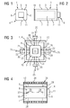
- FIGS. 1 and 2 show two views in each case of a fuel cell pressure vessel 1 in which a hydrogen-oxygen fuel cell 2 (fuel cell for short) is arranged under a protective gas jacket / protective gas envelope 3.
- a hydrogen-oxygen fuel cell 2 fuel cell for short
- the fuel cell pressure vessel 1 (together with the fuel cell arranged therein, also referred to below as a fuel cell module (BZ module) 4) is designed as a parallelepiped container 1 with substantially six planar side walls 5 - 10 arranged at right angles to one another ,
- four sides of the side walls 5-10 form the lateral boundaries of the fuel cell pressure vessel 1 and the BZ module 4, while two 9, 10 of the side walls 5-10 form a bottom 9 and a cover 10 of the fuel cell pressure vessel 1 and the BZ module 4 form.
- the four, the lateral boundaries forming side walls 5 - 8, the bottom 9 and the cover 10 are each arranged perpendicular to each other, so that thereby the cuboid shape of the fuel cell pressure vessel 1 is formed.
- connection region 11 with connections is arranged on the bottom 9 of the BZ module 4.
- This fuel cell 2 or this BZ module 4 is for mobile use, namely in a ship or a submarine, - to its energy or power supply - provided.
- this has special Rack 20 a corresponding special, with reference to the other FIGS 3 to 7 - in there two different versions - clarified holding system or special bracing 21 (receiving device) for receiving or insertion and clamping of the BZ module in the rack 20.
- the rack 20 has at least four pressure screws 22 supporting it on the rack for each of the four lateral side walls 5 - 8 of the fuel cell pressure container 1. Behind the visible pressure screws 22 may be located more, as in FIG. 4 shown as a thread in the profiles 12.
- a pressure screw 22 into its respective threaded bore 28 in the rack 20 can be as a predetermined distance 23 (stop limit) of the pressure screw 22 to the side wall 5, 6, 7 or 8 of the fuel cell pressure vessel 1 realize.
- FIG. 4 illustrates a contact pattern 27, which is formed by the four pressure screws 22 on the respective side wall 5, 6, 7 or 8 during their contact.
- FIG. 4 illustrates an (idealized) contact point 29 at stop the side wall 5, 6, 7 or 8 on a pressure screw 22 on the side wall 5, 6, 7 or 8 from.
- FIG. 4 are in front of and behind the plane still a bar 12 required (not shown).
- FIG. 4 is a cut of FIG. 3 , This together 16 pressure screws 22 are required in this version.
- FIG. 5 shows the BZ module 4 and the fuel cell pressure vessel 1 after insertion into the rack 20 still without acting on the BZ module with the intended, increased operating pressures and the increased inert gas pressure.
- FIG. 6 illustrates as long as until the side walls 5 - 8 of the fuel cell pressure vessel 1 abut the adjusting screws 22 - and the further buckling / deformation or warping 24 of the side walls 5-8 is blocked or prevented.
- the adjusting screws 22 take on the other forces from the increased internal pressure, which would continue to buckle the fuel cell pressure vessel 1 - and pass them through the support of the pressure screws 22 in the rack 20 in the rack 20 a.
- the deformation 24 of the side walls 5 - 8 is thus limited to a permitted level, namely the preset distance 23, limits material stresses in the side walls 5 - 8 to an allowable extent and thus kept within a permissible tolerance range. Exceeding stresses in the side walls 5 - 8 or these causing forces are absorbed by the rack 20.
- the fuel cell pressure vessel 1 which, like FIGS. 5 and 6, inflates when the increased operating pressures or protective gas pressure are applied, thereby causing unacceptably high stresses in its side walls 5 - 8, is tolerated by a certain distance 23 certain tolerance - prevented from further inflation.
- the adjusting screws 22 divert the impermissibly higher forces from the internal pressure into the rack 20.
- this particular rack 20, i. alone with dilemmaigem holding system or bracing 21 the increase of the usable pressure range of the fuel cell pressure vessel 1 achieved - without modifications to the fuel cell pressure vessel 1, to the fuel cell 2 and / or to the BZ module 4 are necessary.
- FIG. 7 shows a further embodiment of the holding system or bracing device 21 for receiving and clamping the BZ module 4 in the rack 20th
- FIG. 7 shows, four adjustable pressure bars 22 - similar acting as Verspannbacken - in the rack 20 (not shown) are arranged here, which prevent buckling of the side walls 5-8 of the fuel cell pressure vessel 1.
- Each of these four pressure strips 22 is provided for an associated side wall 5, 6, 7, or 8 and is already before supplying the BZ module 4 with the increased operating gas pressures or gas pressures along the respective side wall 5, 6, 7 or 8 at or clamped before supplying the BZ module with the increased operating gas pressures or gas pressures the BZ module. 4
- the pressure bars 22 are supported in the rack 20.
Landscapes
- Engineering & Computer Science (AREA)
- Life Sciences & Earth Sciences (AREA)
- Manufacturing & Machinery (AREA)
- Sustainable Development (AREA)
- Sustainable Energy (AREA)
- Chemical & Material Sciences (AREA)
- Chemical Kinetics & Catalysis (AREA)
- Electrochemistry (AREA)
- General Chemical & Material Sciences (AREA)
- Fuel Cell (AREA)
- Transportation (AREA)
- Mechanical Engineering (AREA)
Priority Applications (7)
| Application Number | Priority Date | Filing Date | Title |
|---|---|---|---|
| EP11186187.8A EP2584640A1 (fr) | 2011-10-21 | 2011-10-21 | Bâti de réception avec récipient pressurisé pour piles à combustible |
| ES12188479.5T ES2496002T3 (es) | 2011-10-21 | 2012-10-15 | Bastidor de alojamiento con recipiente a presión para celdas de combustible |
| DK12188479.5T DK2584641T3 (da) | 2011-10-21 | 2012-10-15 | Montagestel med brændstofcelle-trykbeholder |
| EP12188479.5A EP2584641B1 (fr) | 2011-10-21 | 2012-10-15 | Bâti de réception pour une cuve à pression pour piles à combustible |
| PL12188479T PL2584641T3 (pl) | 2011-10-21 | 2012-10-15 | Stojak ustalający ze zbiornikiem ciśnieniowym do ogniw paliwowych |
| AU2012244063A AU2012244063B2 (en) | 2011-10-21 | 2012-10-18 | Mounting frame containing fuel cell pressure vessel |
| KR1020120116688A KR20130044182A (ko) | 2011-10-21 | 2012-10-19 | 연료 전지 압력 용기를 구비한 장착 프레임 |
Applications Claiming Priority (1)
| Application Number | Priority Date | Filing Date | Title |
|---|---|---|---|
| EP11186187.8A EP2584640A1 (fr) | 2011-10-21 | 2011-10-21 | Bâti de réception avec récipient pressurisé pour piles à combustible |
Publications (1)
| Publication Number | Publication Date |
|---|---|
| EP2584640A1 true EP2584640A1 (fr) | 2013-04-24 |
Family
ID=46982486
Family Applications (2)
| Application Number | Title | Priority Date | Filing Date |
|---|---|---|---|
| EP11186187.8A Withdrawn EP2584640A1 (fr) | 2011-10-21 | 2011-10-21 | Bâti de réception avec récipient pressurisé pour piles à combustible |
| EP12188479.5A Not-in-force EP2584641B1 (fr) | 2011-10-21 | 2012-10-15 | Bâti de réception pour une cuve à pression pour piles à combustible |
Family Applications After (1)
| Application Number | Title | Priority Date | Filing Date |
|---|---|---|---|
| EP12188479.5A Not-in-force EP2584641B1 (fr) | 2011-10-21 | 2012-10-15 | Bâti de réception pour une cuve à pression pour piles à combustible |
Country Status (6)
| Country | Link |
|---|---|
| EP (2) | EP2584640A1 (fr) |
| KR (1) | KR20130044182A (fr) |
| AU (1) | AU2012244063B2 (fr) |
| DK (1) | DK2584641T3 (fr) |
| ES (1) | ES2496002T3 (fr) |
| PL (1) | PL2584641T3 (fr) |
Cited By (2)
| Publication number | Priority date | Publication date | Assignee | Title |
|---|---|---|---|---|
| CN109216613A (zh) * | 2018-08-22 | 2019-01-15 | 王嘉静 | 一种保护效果好的稳定型新能源电池箱 |
| WO2023089072A1 (fr) * | 2021-11-18 | 2023-05-25 | Ekpo Fuel Cell Technologies Gmbh | Système de pile à combustible |
Citations (5)
| Publication number | Priority date | Publication date | Assignee | Title |
|---|---|---|---|---|
| EP1406335A2 (fr) * | 2002-10-04 | 2004-04-07 | Nissan Motor Co., Ltd. | Assemblage de piles à combustible |
| US20040121216A1 (en) * | 2002-12-24 | 2004-06-24 | Scott Blanchet | Fuel cell stack compressive loading system |
| US20090042082A1 (en) * | 2005-04-05 | 2009-02-12 | Rolls-Royce Plc | Fuel cell arrangement |
| JP2010037789A (ja) * | 2008-08-04 | 2010-02-18 | Takenaka Komuten Co Ltd | 免震構造、建物及び免震建物 |
| DE102008059844A1 (de) * | 2008-12-01 | 2010-06-10 | Man Nutzfahrzeuge Aktiengesellschaft | Vorrichtung zum Befestigen eines oder mehrerer Behälter an einem Fahrzeugbauteil |
-
2011
- 2011-10-21 EP EP11186187.8A patent/EP2584640A1/fr not_active Withdrawn
-
2012
- 2012-10-15 EP EP12188479.5A patent/EP2584641B1/fr not_active Not-in-force
- 2012-10-15 DK DK12188479.5T patent/DK2584641T3/da active
- 2012-10-15 ES ES12188479.5T patent/ES2496002T3/es active Active
- 2012-10-15 PL PL12188479T patent/PL2584641T3/pl unknown
- 2012-10-18 AU AU2012244063A patent/AU2012244063B2/en not_active Ceased
- 2012-10-19 KR KR1020120116688A patent/KR20130044182A/ko not_active Withdrawn
Patent Citations (5)
| Publication number | Priority date | Publication date | Assignee | Title |
|---|---|---|---|---|
| EP1406335A2 (fr) * | 2002-10-04 | 2004-04-07 | Nissan Motor Co., Ltd. | Assemblage de piles à combustible |
| US20040121216A1 (en) * | 2002-12-24 | 2004-06-24 | Scott Blanchet | Fuel cell stack compressive loading system |
| US20090042082A1 (en) * | 2005-04-05 | 2009-02-12 | Rolls-Royce Plc | Fuel cell arrangement |
| JP2010037789A (ja) * | 2008-08-04 | 2010-02-18 | Takenaka Komuten Co Ltd | 免震構造、建物及び免震建物 |
| DE102008059844A1 (de) * | 2008-12-01 | 2010-06-10 | Man Nutzfahrzeuge Aktiengesellschaft | Vorrichtung zum Befestigen eines oder mehrerer Behälter an einem Fahrzeugbauteil |
Cited By (2)
| Publication number | Priority date | Publication date | Assignee | Title |
|---|---|---|---|---|
| CN109216613A (zh) * | 2018-08-22 | 2019-01-15 | 王嘉静 | 一种保护效果好的稳定型新能源电池箱 |
| WO2023089072A1 (fr) * | 2021-11-18 | 2023-05-25 | Ekpo Fuel Cell Technologies Gmbh | Système de pile à combustible |
Also Published As
| Publication number | Publication date |
|---|---|
| AU2012244063B2 (en) | 2014-02-27 |
| AU2012244063A1 (en) | 2013-05-09 |
| KR20130044182A (ko) | 2013-05-02 |
| ES2496002T3 (es) | 2014-09-18 |
| EP2584641B1 (fr) | 2014-06-04 |
| DK2584641T3 (da) | 2014-09-15 |
| PL2584641T3 (pl) | 2014-11-28 |
| EP2584641A1 (fr) | 2013-04-24 |
Similar Documents
| Publication | Publication Date | Title |
|---|---|---|
| DE102015223488B4 (de) | Vorrichtung und Verfahren zum Befestigen eines Brennstoffzellenstapels | |
| DE112008000472B4 (de) | Brennstoffzelle und Befestigungsvorrichtung für eine Brennstoffzelle | |
| DE112015001911B4 (de) | Elektrisches Fahrzeug | |
| WO1998054777A1 (fr) | Systeme de pile a combustible | |
| KR102525589B1 (ko) | 수전해 스택 모듈 적층 장치 | |
| EP2514000A1 (fr) | Boîtier de batterie destiné à loger des dispositifs électrochimiques accumulateurs d'énergie | |
| DE102012018243A1 (de) | Verfahren und System zum Betreiben eines Elektrolyseurs | |
| EP2584641B1 (fr) | Bâti de réception pour une cuve à pression pour piles à combustible | |
| DE102013203108A1 (de) | Schutz für Abblasventile von Akkumulatorzellen | |
| EP3799667B1 (fr) | Procédé de traitement du gaz résiduel contenant de l'hydrogène et de l'oxygène des piles à combustible ainsi que système de traitement du gaz résiduel | |
| WO2018091522A1 (fr) | Module de piles à combustible, système de piles à combustible et procédé de fonctionnement | |
| EP2422397B1 (fr) | Système de piles à combustible | |
| DE112014006238B4 (de) | Brennstoffzellenstapel, der einen Endplattenaufbau mit einer sich verjüngenden Federplatte besitzt | |
| WO2022161595A1 (fr) | Procédé de fonctionnement d'un empilement électrolytique | |
| DE102017223452A1 (de) | Verfahren zum Freigeben eines Brennstoffzellensystems sowie Brennstoffzellensystem | |
| EP1240043A1 (fr) | Dispositif de piles a combustible pour la propulsion d'un vehicule | |
| DE102016212250A1 (de) | Kraftfahrzeug und Verfahren zum Fördern von Brennstoff zu einem Brennstoffverbraucher eines Kraftfahrzeugs | |
| WO2021110347A1 (fr) | Pile à combustible, empilement de piles à combustible et procédé pour faire fonctionner un empilement de piles à combustible | |
| WO2018091520A2 (fr) | Module de piles à combustible, système de piles à combustible et procédé permettant de faire fonctionner ledit module | |
| DE102019206175B3 (de) | Brennstoffzellenanordnung | |
| EP1936726A1 (fr) | Agencement de cellules de combustible et procédé de fonctionnement d'une cellule de combustible | |
| DE102019214288A1 (de) | Verfahren zum Betreiben eines Brennstoffzellensystems, Brennstoffzellensystem | |
| DE102012101023B4 (de) | Brennstoffzellenvorrichtung und Verfahren zum Herstellen einer Brennstoffzellenvorrichtung | |
| DE102014221976A1 (de) | Brennstoffzellensystem und Betriebsverfahren eines Brennstoffzellensystems | |
| DE102023213298A1 (de) | Fluiddichter elektrochemischer Zellenstapel |
Legal Events
| Date | Code | Title | Description |
|---|---|---|---|
| PUAI | Public reference made under article 153(3) epc to a published international application that has entered the european phase |
Free format text: ORIGINAL CODE: 0009012 |
|
| AK | Designated contracting states |
Kind code of ref document: A1 Designated state(s): AL AT BE BG CH CY CZ DE DK EE ES FI FR GB GR HR HU IE IS IT LI LT LU LV MC MK MT NL NO PL PT RO RS SE SI SK SM TR |
|
| AX | Request for extension of the european patent |
Extension state: BA ME |
|
| STAA | Information on the status of an ep patent application or granted ep patent |
Free format text: STATUS: THE APPLICATION IS DEEMED TO BE WITHDRAWN |
|
| 18D | Application deemed to be withdrawn |
Effective date: 20131025 |