EP2584655B1 - Connecteur - Google Patents
Connecteur Download PDFInfo
- Publication number
- EP2584655B1 EP2584655B1 EP11795714.2A EP11795714A EP2584655B1 EP 2584655 B1 EP2584655 B1 EP 2584655B1 EP 11795714 A EP11795714 A EP 11795714A EP 2584655 B1 EP2584655 B1 EP 2584655B1
- Authority
- EP
- European Patent Office
- Prior art keywords
- housing
- connector
- cavity
- terminal
- nut
- Prior art date
- Legal status (The legal status is an assumption and is not a legal conclusion. Google has not performed a legal analysis and makes no representation as to the accuracy of the status listed.)
- Not-in-force
Links
- 238000003780 insertion Methods 0.000 claims description 23
- 230000037431 insertion Effects 0.000 claims description 23
- 210000000078 claw Anatomy 0.000 claims description 8
- 238000004078 waterproofing Methods 0.000 claims description 7
- UQMRAFJOBWOFNS-UHFFFAOYSA-N butyl 2-(2,4-dichlorophenoxy)acetate Chemical compound CCCCOC(=O)COC1=CC=C(Cl)C=C1Cl UQMRAFJOBWOFNS-UHFFFAOYSA-N 0.000 description 6
- 230000009467 reduction Effects 0.000 description 5
- 230000000717 retained effect Effects 0.000 description 3
- 238000004891 communication Methods 0.000 description 2
- 239000004020 conductor Substances 0.000 description 2
- 239000000463 material Substances 0.000 description 2
- 230000007246 mechanism Effects 0.000 description 2
- 239000007769 metal material Substances 0.000 description 2
- 238000000034 method Methods 0.000 description 2
- 238000012856 packing Methods 0.000 description 2
- RYGMFSIKBFXOCR-UHFFFAOYSA-N Copper Chemical compound [Cu] RYGMFSIKBFXOCR-UHFFFAOYSA-N 0.000 description 1
- 230000000903 blocking effect Effects 0.000 description 1
- 239000000470 constituent Substances 0.000 description 1
- 229910052802 copper Inorganic materials 0.000 description 1
- 239000010949 copper Substances 0.000 description 1
- 238000005520 cutting process Methods 0.000 description 1
- 238000004519 manufacturing process Methods 0.000 description 1
- 238000012986 modification Methods 0.000 description 1
- 230000004048 modification Effects 0.000 description 1
- 230000002093 peripheral effect Effects 0.000 description 1
- 239000011347 resin Substances 0.000 description 1
- 229920005989 resin Polymers 0.000 description 1
Images


Classifications
-
- H—ELECTRICITY
- H01—ELECTRIC ELEMENTS
- H01R—ELECTRICALLY-CONDUCTIVE CONNECTIONS; STRUCTURAL ASSOCIATIONS OF A PLURALITY OF MUTUALLY-INSULATED ELECTRICAL CONNECTING ELEMENTS; COUPLING DEVICES; CURRENT COLLECTORS
- H01R13/00—Details of coupling devices of the kinds covered by groups H01R12/70 or H01R24/00 - H01R33/00
- H01R13/40—Securing contact members in or to a base or case; Insulating of contact members
- H01R13/405—Securing in non-demountable manner, e.g. moulding, riveting
- H01R13/415—Securing in non-demountable manner, e.g. moulding, riveting by permanent deformation of contact member
-
- H—ELECTRICITY
- H01—ELECTRIC ELEMENTS
- H01R—ELECTRICALLY-CONDUCTIVE CONNECTIONS; STRUCTURAL ASSOCIATIONS OF A PLURALITY OF MUTUALLY-INSULATED ELECTRICAL CONNECTING ELEMENTS; COUPLING DEVICES; CURRENT COLLECTORS
- H01R11/00—Individual connecting elements providing two or more spaced connecting locations for conductive members which are, or may be, thereby interconnected, e.g. end pieces for wires or cables supported by the wire or cable and having means for facilitating electrical connection to some other wire, terminal, or conductive member, blocks of binding posts
- H01R11/11—End pieces or tapping pieces for wires, supported by the wire and for facilitating electrical connection to some other wire, terminal or conductive member
- H01R11/12—End pieces terminating in an eye, hook, or fork
-
- H—ELECTRICITY
- H01—ELECTRIC ELEMENTS
- H01R—ELECTRICALLY-CONDUCTIVE CONNECTIONS; STRUCTURAL ASSOCIATIONS OF A PLURALITY OF MUTUALLY-INSULATED ELECTRICAL CONNECTING ELEMENTS; COUPLING DEVICES; CURRENT COLLECTORS
- H01R13/00—Details of coupling devices of the kinds covered by groups H01R12/70 or H01R24/00 - H01R33/00
- H01R13/46—Bases; Cases
- H01R13/52—Dustproof, splashproof, drip-proof, waterproof, or flameproof cases
- H01R13/5205—Sealing means between cable and housing, e.g. grommet
-
- H—ELECTRICITY
- H01—ELECTRIC ELEMENTS
- H01R—ELECTRICALLY-CONDUCTIVE CONNECTIONS; STRUCTURAL ASSOCIATIONS OF A PLURALITY OF MUTUALLY-INSULATED ELECTRICAL CONNECTING ELEMENTS; COUPLING DEVICES; CURRENT COLLECTORS
- H01R2103/00—Two poles
Definitions
- the present invention relates to a connector with terminals each of which is connected to a cable.
- connection portion is increased in size.
- the connector when the connector is constructed that this terminal is inserted from the rear end side of a housing, there must be provided a large cavity into which the terminal is inserted to pass it through. As a result, an increase in size of the connector is brought about.
- the present invention has been made in view of the above circumstances, and it is an object of the present invention to provide a connector that is capable of reducing a size while suppressing a cost to the utmost.
- the connector according to the present invention has following aspects (1) to (3) as features.
- the nut is held at the front end surface of the housing, and the plate-like connection portion protruded from the front end portion of the housing is bent and then arranged along the front end surface of the housing after the terminal is inserted into the cavity. Therefore, in comparison with the connector having such a configuration that the terminal, in which the internal thread is formed or onto which the nut is fixed, is inserted into the cavities of the housing, the cavity can be reduced in size, and thus a reduction in size of the connector can be achieved. Also, the connection portion of the terminal protruded from the front end portion of the housing is bent and arranged along the front end surface of the housing. Therefore, the disengagement of the terminal can be prevented by engaging the connection portion with the housing, and therefore an increase in size and an increase in cost due to the provision of the complicated shape can be suppressed.
- a size of the cavity can be reduced. Therefore, a reduction in size of the waterproofing plug that blocks the cavity to make watertight an inside of the cavity can be achieved, and a reduction in cost can be achieved.
- connection portion of the terminal is retained and held by the retaining claw on the front end surface of the housing. Therefore, when the terminal is to be connected to the terminal of the opposing connector by the bolts, the bolt can be passed smoothly through the insertion hole of the connection portion of the terminal respectively and then this bolt can be screwed into the nut respectively, and thus the terminals of both connectors can be engaged mutually and connected satisfactorily.
- the connector that is capable of reducing a size while suppressing a cost to the utmost can be provided.
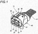
- FIG.1 is a perspective view of a connector according to an embodiment of the present invention
- FIG.2 is an exploded perspective view of the connector according to the embodiment of the present invention
- FIG.3 is a sectional view of the connector according to the embodiment of the present invention
- FIG.4 is a rear view of a housing constituting the connector according to the embodiment of the present invention.
- a connector 11 includes a plurality of terminals 20, a housing 30 in which these terminals 20 are housed, a shielding shell 40 for covering this housing 30, and a shielding member 41 for covering the housing 30 and cables 26, which are exposed from the rear end of the housing 30.
- the terminals 20 are formed by applying the press working to a conductive metal material such as a copper plate, or the like.
- Each of the terminals 20 has a press-fitted portion 21 located on the rear end side, and a plate-like connection portion 22 extended toward the insertion direction to a cavity 31 that is formed in the housing 30 and is described later.
- a conductor of the cable 26 is press-fitted and fixed to the press-fitted portion 21 and is connected electrically thereto.
- the connection portion 22 has a bent portion 23, which is bent toward one surface side, in its middle portion. Also, an insertion hole 24 is formed in the connection portion 22 between a top end of the connection portion 22 and the bent portion 23.
- a cylindrical rubber plug (waterproofing plug) 27 is fitted to the cable 26, which is connected to this terminal 20, on the terminal 20 side. Also, a rear holder 28 is provided on the opposite side to the terminal 20 more away from the terminal than the rubber plug 27.
- the rubber plug 27 makes watertight between the housing 30 and the cable 26, and the rear holder 28 holds the rubber plug 27 in a predetermined position.
- the housing 30 is formed by an insulating resin material, and has a plurality of cavities 31 in each of which the terminal 20 is housed, as shown in FIG.4 .
- Each of these cavities 31 has in sequence a connection portion insertion hole 32 through which the connection portion 22 of the terminal 20 is passed, a press-fitted portion containing hole 33 in which the press-fitted portion 21 of the terminal 20 is arranged, and a rubber plug containing hole 34 in which the rubber plug 27 and the rear holder 28 are contained, from the top end side.
- a wall portion formed at a boundary between the convection portion insertion hole 32 and the press-fitted portion containing hole 33 is used as an insertion restricting wall 31 a that restricts the insertion of the terminal 20.
- the terminal 20 that is not bent yet is inserted into each of the cavities 31 from the rear end side of the housing 30.
- this rubber plug 27 comes liquid-tightly into contact with the inner peripheral surface of the rubber plug containing hole 34 in the cavity 31. Accordingly, the part of the cavity 31 located on the forwarder side than the fitting location of the rubber plug 27 is made waterproof.
- Nut holding recess portions 35 are formed on a front end surface of the housing 30.
- An internal thread 36a is formed in a center of a nut 36 that is shaped into a rectangular shape when viewed from the top. This nut 36 is housed and held in the nut holding recess portions 35 respectively.
- connection portions 22 are arranged on the front end surface of this housing 30.
- the insertion hole 24 formed in the connection portion 22 is placed in communication with the internal thread 36a of the nut 36 that is housed in the nut holding recess portion 35.
- a retaining claw 37 is formed at upper and lower corners on both sides of the nut holding recess portions 35 on the front end surface of the housing 30 respectively.
- the connection portions 22 that are arranged along the front end surface of the housing 30 respectively are retrained and held by these retaining claws 37.
- a packing member 38 is provided to the outer periphery of the housing 30 all around the entire circumference. This packing member 38 comes into tight contact with the opposing connector to seal it. Also, a locking mechanism portion 39 is provided to a top portion of the housing 30. When the connector 11 is connected to the opposing connector, this locking mechanism portion 39 engages with the opposing connector to keep the connected state.
- the shielding shell 40 is formed of conductive metal material, and is fitted onto the housing 30 from its rear end side to cover the periphery of the housing 30. Also, the shielding member 41 formed of conductive material is provided to the rear end side of the shielding shell 40. The housing 30 and the cables 26 both exposed at the rear end of the shielding shell 40 are covered with this shielding member 41. Then, the connector 11 is shielded with the shielding shell 40 and the shielding member 41.
- FIG.5(a) to FIG.5(c) are sectional views explaining the procedures of assembling the connector respectively.
- the terminal 20 that is not bent yet is inserted into the cavities 31 of the housing 30 from the rear end side respectively, as indicated with an arrow A in FIG.5(a) .
- the press-fitted portion 21 comes into contact with the insertion restricting walls 31a respectively. Accordingly, the insertion of the terminal 20 into the cavity 31 is restricted, and thus the excessive insertion of the terminal 20 is prevented.
- the connection portions 22 each containing the bent portion 23 are set to their protruded state from the front end portion of the housing 30.
- the nut 36 is fitted into the nut holding recess portions 35 on the front end surface of the housing 30 respectively, as indicated with an arrow B in FIG.5(a) .
- the nuts 36 are held at the front end portion of the housing 30.
- connection portions 22 are bent by about 90 ° at the bent portion 23 respectively, as indicated with an arrow C in FIG.5(b) , in the state that the connection portions 22 of the terminals 20 are protruded sufficiently from the top end of the housing 30.
- connection portions 22 are bent at the bent portion 23 respectively
- the terminals 20 are pulled back toward the rear end side in the opposite direction to the insertion direction, as indicated with an arrow D in FIG.5(c) .
- connection portions 22 being bent at the bent portion 23 respectively are positioned along the front end surface of the housing 30 to cover the nut 36 respectively, and the insertion holes 24 are placed in communication with the internal threads 36a of the nuts 36 respectively. Then, the connection portions 22 of the terminals 20 are retained and held by the retaining claws 37, which are provided to the front end surface of this housing 30, respectively.
- the rubber plug 27 and the rear holder 28, through which the cable 26 is passed in advance respectively, are fitted into the rubber plug containing holes 34 of the cavities 31 respectively.
- the shielding shell 40 is fitted onto the housing 30, and then the rear end of the housing 30 and the cables 26 are covered with the shielding member 41.
- the nuts 36 are held on the front end surface of the housing, 30, and the plate-like connection portions 22, each of which is inserted into the cavity 31 and is protruded from the front end portion of the housing 30, are bent and positioned along the front end surface of the housing 30.
- the cavity can be reduced in size, and thus a reduction in size of the connector can be attained.
- the connection portions 22 of the terminals 20 protruded from the front end portion of the housing 30 are bent and arranged along the front end surface of the housing 30.
- the cavity 31 can be reduced in size. Therefore, the rubber plug 27 for blocking the cavity 31 to make it watertight can be reduced in size, and a reduction in cost of the cavity 31 can be attained.
- connection portions 22 of the terminals 20 are retained and held by the retaining claws 37 on the front end surface of the housing 30 respectively. Therefore, when the terminals 20 are connected to the terminals of the opposing connector by the bolts, the bolt can be passed smoothly through the insertion holes 24 of the connection portions 22 of the terminals 20 respectively and then this bolt can be screwed into the nuts 36 respectively. Accordingly, the terminals of both connectors can be engaged satisfactorily and be connected mutually.
- FIG.6 to FIG.9 a reference example is shown in FIG.6 to FIG.9 hereunder.
- FIG.6 is a perspective view of a connector in a reference example
- FIG.7 is an exploded perspective view of the connector in the reference example
- FIG.8 is a sectional view of the connector in the reference example
- FIG.9 is a rear view of a housing constituting the connector in the reference example.
- the connector in the reference example includes terminals 2 to each of which a cable 1 is connected, a housing 3 having cavities 3a into each of which the terminal 2 is inserted from the rear end side, a shielding shell 4 fitted to cover the housing 3, and a shielding member 5 for covering the housing 3 and the cables 1 both exposed at the rear end of the shielding shell 4.
- a nut press-fitted portion 2b is formed at connection portions 2a of the terminals 2 respectively, and a nut 6 is fitted to the nut press-fitted portions 2b with pressure and is held thereon respectively.
- connection portion 2a of the terminal 2 that holds the nut 6 is increased in size. Therefore, because the large connection portion 2a should be inserted into the cavity 3a and be passed through there, the cavity 3a of the housing 3 must also be increased in size.
- lances 3b must be provided to the housing 3.
- this connector needs the large cavity 3a and also the lance 3b must be provided. Therefore, an increase in size of the connector is brought about. Also, according to an increase in size of a rubber plug 7, which blocks the cavity 3a to make it watertight, and complication of the configuration due to the provision of the lances 3b, an increase in cost is brought about.
- the present invention is not limited to the above embodiment, and variations, improvements, and the like can be applied appropriately.
- material, shape, dimension, number, arranged location, etc. of respective constituent elements in the above embodiment may be chosen arbitrarily if these elements can attain the present invention, and are not limited.
- the connector that is capable of reducing a size while suppressing a cost to the utmost can be provided.
Landscapes
- Connector Housings Or Holding Contact Members (AREA)
- Connections By Means Of Piercing Elements, Nuts, Or Screws (AREA)
Claims (4)
- Connecteur (11) comprenant :un boîtier (30) ;une cavité (31) formée dans le boîtier (30) ;une borne (20) qui est connectée à un câble (26) et est insérée dans la cavité (31) depuis le côté d'extrémité arrière du boîtier (30) ; etun écrou (36) maintenu dans la partie d'extrémité avant du boîtier (30),dans lequel la borne (20) comporte une partie de connexion en forme de plaque (22) s'étendant dans la direction d'insertion de la cavité (31) et un trou d'insertion (24) formé dans la partie de connexion (22),
caractérisé en ce que
la partie de connexion (22) qui est insérée dans la cavité (31) et fait saillie depuis la partie d'extrémité avant du boîtier (30) est courbée de façon à être agencée le long de la surface d'extrémité avant du boîtier (30) afin que le trou d'insertion (24) soit aligné avec le taraudage interne (36a) de l'écrou (36). - Connecteur (11) selon la revendication 1, dans lequel un bouchon d'étanchéité vis-à-vis de l'eau (27) est ajusté sur le câble (26) ; et
dans lequel le bouchon d'étanchéité vis-à-vis de l'eau (27) est en prise avec la cavité (31) pour rendre l'intérieur de la cavité (31) étanche vis-à-vis de l'eau dans l'état dans lequel la borne (20) est insérée dans la cavité (31). - Connecteur (11) selon la revendication 1 ou 2, dans lequel une mâchoire de retenue (37) est prévue sur la surface d'extrémité avant du boîtier (30) pour retenir et maintenir la partie de connexion (22) de la borne (20).
- Connecteur (11) selon l'une quelconque des revendications 1 à 3, dans lequel une partie de maintien d'écrou en retrait (3) est formée sur la surface d'extrémité avant du boîtier (30) ; et
dans lequel l'écrou (36) est ajusté dans la partie de maintien d'écrou en retrait (36) et est maintenu au niveau de la partie d'extrémité avant du boîtier (30).
Applications Claiming Priority (2)
| Application Number | Priority Date | Filing Date | Title |
|---|---|---|---|
| JP2010135910A JP5565946B2 (ja) | 2010-06-15 | 2010-06-15 | コネクタ |
| PCT/JP2011/063540 WO2011158809A1 (fr) | 2010-06-15 | 2011-06-13 | Connecteur |
Publications (3)
| Publication Number | Publication Date |
|---|---|
| EP2584655A1 EP2584655A1 (fr) | 2013-04-24 |
| EP2584655A4 EP2584655A4 (fr) | 2014-12-31 |
| EP2584655B1 true EP2584655B1 (fr) | 2016-08-31 |
Family
ID=45348208
Family Applications (1)
| Application Number | Title | Priority Date | Filing Date |
|---|---|---|---|
| EP11795714.2A Not-in-force EP2584655B1 (fr) | 2010-06-15 | 2011-06-13 | Connecteur |
Country Status (5)
| Country | Link |
|---|---|
| US (1) | US8641441B2 (fr) |
| EP (1) | EP2584655B1 (fr) |
| JP (1) | JP5565946B2 (fr) |
| CN (1) | CN102696151B (fr) |
| WO (1) | WO2011158809A1 (fr) |
Families Citing this family (8)
| Publication number | Priority date | Publication date | Assignee | Title |
|---|---|---|---|---|
| JP5751875B2 (ja) * | 2011-03-22 | 2015-07-22 | 矢崎総業株式会社 | シールドコネクタ |
| US9318849B2 (en) * | 2011-04-14 | 2016-04-19 | Yazaki Corporation | Shielded connector |
| EP2763255B1 (fr) * | 2011-09-29 | 2019-07-31 | Yazaki Corporation | Connecteur comprenant une pluralite de contacts et un boîtier |
| DE102011087762B4 (de) * | 2011-12-05 | 2025-08-07 | Robert Bosch Gmbh | Gerätedurchführung zum Durchführen einer Hochfrequenzkabelanordnung durch ein Gehäuse eines Gerätes |
| JP5775008B2 (ja) * | 2012-02-02 | 2015-09-09 | 住友電装株式会社 | コネクタ装置 |
| JP5772718B2 (ja) * | 2012-05-22 | 2015-09-02 | 日立金属株式会社 | シールドシェルと編組シールドとの接続構造及びワイヤハーネス |
| DE102017104326B3 (de) | 2017-03-02 | 2018-09-06 | Amphenol-Tuchel Electronics Gmbh | Hochstromverbinder mit Hochstromkontaktkörpern zur Verschraubung |
| JP7655038B2 (ja) * | 2021-03-26 | 2025-04-02 | 住友電装株式会社 | コネクタ |
Family Cites Families (18)
| Publication number | Priority date | Publication date | Assignee | Title |
|---|---|---|---|---|
| DE1111261B (de) * | 1959-04-03 | 1961-07-20 | Elektroschaltgeraete Eisenach | Steckerkontaktstueck |
| FR2614473B1 (fr) * | 1987-04-22 | 1989-07-07 | Power Compact | Borne a ecrou prisonnier pour connecteur de puissance de modules electroniques |
| US5810610A (en) | 1995-08-08 | 1998-09-22 | Sumitomo Wiring Systems, Ltd. | Device for connecting a cable, in particular a high-voltage cable for an internal combustion engine |
| JP3085153B2 (ja) * | 1995-08-08 | 2000-09-04 | 住友電装株式会社 | 内燃機関用高圧電線の接続装置 |
| JPH1012292A (ja) * | 1996-06-24 | 1998-01-16 | Yazaki Corp | コントロールユニット |
| JP3827908B2 (ja) * | 2000-03-06 | 2006-09-27 | 株式会社オートネットワーク技術研究所 | 端子金具 |
| JP2002270254A (ja) * | 2001-03-12 | 2002-09-20 | Auto Network Gijutsu Kenkyusho:Kk | 端子金具及びコネクタ |
| JP3909680B2 (ja) * | 2002-04-25 | 2007-04-25 | 矢崎総業株式会社 | コネクタ構造 |
| JP2005019319A (ja) * | 2003-06-27 | 2005-01-20 | Auto Network Gijutsu Kenkyusho:Kk | 機器用コネクタ |
| JP2006271130A (ja) * | 2005-03-24 | 2006-10-05 | Sumitomo Wiring Syst Ltd | 電気接続箱 |
| JP4761931B2 (ja) * | 2005-10-27 | 2011-08-31 | 矢崎総業株式会社 | 端子可動コネクタ |
| CN2938397Y (zh) * | 2006-06-23 | 2007-08-22 | 徐州云意电气发展有限公司 | 汽车整流器的输入端结构 |
| JP4932659B2 (ja) * | 2007-10-03 | 2012-05-16 | 矢崎総業株式会社 | シールドコネクタおよびシールドコネクタの製造方法 |
| JP4970220B2 (ja) * | 2007-11-16 | 2012-07-04 | 矢崎総業株式会社 | シールドコネクタ |
| JP5095446B2 (ja) * | 2008-03-05 | 2012-12-12 | 矢崎総業株式会社 | コネクタ |
| JP2010135910A (ja) | 2008-12-02 | 2010-06-17 | Canon Inc | ユーザー設定情報管理システム、ユーザー設定情報管理方法、プログラム、記憶媒体 |
| JP5394821B2 (ja) * | 2009-05-22 | 2014-01-22 | 矢崎総業株式会社 | 防水栓、及び、該防水栓を有するコネクタ |
| JP5524687B2 (ja) * | 2010-04-13 | 2014-06-18 | 矢崎総業株式会社 | コネクタ |
-
2010
- 2010-06-15 JP JP2010135910A patent/JP5565946B2/ja not_active Expired - Fee Related
-
2011
- 2011-06-13 WO PCT/JP2011/063540 patent/WO2011158809A1/fr not_active Ceased
- 2011-06-13 EP EP11795714.2A patent/EP2584655B1/fr not_active Not-in-force
- 2011-06-13 CN CN201180004160.8A patent/CN102696151B/zh not_active Expired - Fee Related
- 2011-06-13 US US13/497,548 patent/US8641441B2/en not_active Expired - Fee Related
Also Published As
| Publication number | Publication date |
|---|---|
| EP2584655A4 (fr) | 2014-12-31 |
| JP5565946B2 (ja) | 2014-08-06 |
| WO2011158809A1 (fr) | 2011-12-22 |
| US8641441B2 (en) | 2014-02-04 |
| CN102696151B (zh) | 2015-11-25 |
| JP2012003882A (ja) | 2012-01-05 |
| US20120270430A1 (en) | 2012-10-25 |
| CN102696151A (zh) | 2012-09-26 |
| EP2584655A1 (fr) | 2013-04-24 |
Similar Documents
| Publication | Publication Date | Title |
|---|---|---|
| EP2584655B1 (fr) | Connecteur | |
| EP2610975B1 (fr) | Dispositif comprenant un élément de fixation de fils et son procédé d'assemblage | |
| US9209582B2 (en) | Connector | |
| US9332668B2 (en) | Electronic circuit unit capable of external connection | |
| US9929491B2 (en) | Live portion protection structure and connector | |
| US8333616B2 (en) | Low-profile cable assembly with good function EMI prevention | |
| US8951065B2 (en) | Connection structure of conductive paths | |
| US5911595A (en) | Low profile angular connector device and method | |
| EP2475049B1 (fr) | Connecteur | |
| US9124016B2 (en) | Connector with covering wall | |
| EP2602881B1 (fr) | Structure anticorrosion pour partie de branchement de fil | |
| EP2980931B1 (fr) | Connecteur electrique | |
| US9033747B2 (en) | Connector | |
| KR20150070271A (ko) | 전기 커넥터 | |
| CN107210565A (zh) | 屏蔽连接器 | |
| EP2161791A2 (fr) | Connecteur de câble | |
| JP7549785B2 (ja) | コネクタ | |
| US20190148873A1 (en) | Electrical device having a seal assembly | |
| JP5170013B2 (ja) | シールドコネクタ | |
| US20130148313A1 (en) | Electronic circuit unit to be mounted on automatic transmission for vehicle and manufacturing method thereof | |
| JP4278846B2 (ja) | 機器接続用シールドコネクタ | |
| JP2011060426A (ja) | コネクタ | |
| JP7388264B2 (ja) | コネクタ、およびコネクタ付きケーブル | |
| WO2013171982A1 (fr) | Connecteur | |
| WO2020138037A1 (fr) | Fil électrique avec borne fixée, et connecteur |
Legal Events
| Date | Code | Title | Description |
|---|---|---|---|
| PUAI | Public reference made under article 153(3) epc to a published international application that has entered the european phase |
Free format text: ORIGINAL CODE: 0009012 |
|
| 17P | Request for examination filed |
Effective date: 20120315 |
|
| AK | Designated contracting states |
Kind code of ref document: A1 Designated state(s): AL AT BE BG CH CY CZ DE DK EE ES FI FR GB GR HR HU IE IS IT LI LT LU LV MC MK MT NL NO PL PT RO RS SE SI SK SM TR |
|
| DAX | Request for extension of the european patent (deleted) | ||
| A4 | Supplementary search report drawn up and despatched |
Effective date: 20141127 |
|
| RIC1 | Information provided on ipc code assigned before grant |
Ipc: H01R 4/34 20060101AFI20141121BHEP Ipc: H01R 11/12 20060101ALI20141121BHEP Ipc: H01R 13/415 20060101ALI20141121BHEP Ipc: H01R 13/46 20060101ALI20141121BHEP Ipc: H01R 13/52 20060101ALI20141121BHEP |
|
| GRAP | Despatch of communication of intention to grant a patent |
Free format text: ORIGINAL CODE: EPIDOSNIGR1 |
|
| INTG | Intention to grant announced |
Effective date: 20160426 |
|
| GRAS | Grant fee paid |
Free format text: ORIGINAL CODE: EPIDOSNIGR3 |
|
| GRAA | (expected) grant |
Free format text: ORIGINAL CODE: 0009210 |
|
| AK | Designated contracting states |
Kind code of ref document: B1 Designated state(s): AL AT BE BG CH CY CZ DE DK EE ES FI FR GB GR HR HU IE IS IT LI LT LU LV MC MK MT NL NO PL PT RO RS SE SI SK SM TR |
|
| REG | Reference to a national code |
Ref country code: CH Ref legal event code: EP Ref country code: GB Ref legal event code: FG4D |
|
| REG | Reference to a national code |
Ref country code: IE Ref legal event code: FG4D |
|
| REG | Reference to a national code |
Ref country code: DE Ref legal event code: R096 Ref document number: 602011029913 Country of ref document: DE |
|
| REG | Reference to a national code |
Ref country code: AT Ref legal event code: REF Ref document number: 825698 Country of ref document: AT Kind code of ref document: T Effective date: 20161015 |
|
| REG | Reference to a national code |
Ref country code: LT Ref legal event code: MG4D |
|
| REG | Reference to a national code |
Ref country code: NL Ref legal event code: MP Effective date: 20160831 |
|
| REG | Reference to a national code |
Ref country code: AT Ref legal event code: MK05 Ref document number: 825698 Country of ref document: AT Kind code of ref document: T Effective date: 20160831 |
|
| PG25 | Lapsed in a contracting state [announced via postgrant information from national office to epo] |
Ref country code: FI Free format text: LAPSE BECAUSE OF FAILURE TO SUBMIT A TRANSLATION OF THE DESCRIPTION OR TO PAY THE FEE WITHIN THE PRESCRIBED TIME-LIMIT Effective date: 20160831 Ref country code: HR Free format text: LAPSE BECAUSE OF FAILURE TO SUBMIT A TRANSLATION OF THE DESCRIPTION OR TO PAY THE FEE WITHIN THE PRESCRIBED TIME-LIMIT Effective date: 20160831 Ref country code: LT Free format text: LAPSE BECAUSE OF FAILURE TO SUBMIT A TRANSLATION OF THE DESCRIPTION OR TO PAY THE FEE WITHIN THE PRESCRIBED TIME-LIMIT Effective date: 20160831 Ref country code: RS Free format text: LAPSE BECAUSE OF FAILURE TO SUBMIT A TRANSLATION OF THE DESCRIPTION OR TO PAY THE FEE WITHIN THE PRESCRIBED TIME-LIMIT Effective date: 20160831 Ref country code: NO Free format text: LAPSE BECAUSE OF FAILURE TO SUBMIT A TRANSLATION OF THE DESCRIPTION OR TO PAY THE FEE WITHIN THE PRESCRIBED TIME-LIMIT Effective date: 20161130 |
|
| PG25 | Lapsed in a contracting state [announced via postgrant information from national office to epo] |
Ref country code: ES Free format text: LAPSE BECAUSE OF FAILURE TO SUBMIT A TRANSLATION OF THE DESCRIPTION OR TO PAY THE FEE WITHIN THE PRESCRIBED TIME-LIMIT Effective date: 20160831 Ref country code: LV Free format text: LAPSE BECAUSE OF FAILURE TO SUBMIT A TRANSLATION OF THE DESCRIPTION OR TO PAY THE FEE WITHIN THE PRESCRIBED TIME-LIMIT Effective date: 20160831 Ref country code: AT Free format text: LAPSE BECAUSE OF FAILURE TO SUBMIT A TRANSLATION OF THE DESCRIPTION OR TO PAY THE FEE WITHIN THE PRESCRIBED TIME-LIMIT Effective date: 20160831 Ref country code: GR Free format text: LAPSE BECAUSE OF FAILURE TO SUBMIT A TRANSLATION OF THE DESCRIPTION OR TO PAY THE FEE WITHIN THE PRESCRIBED TIME-LIMIT Effective date: 20161201 Ref country code: NL Free format text: LAPSE BECAUSE OF FAILURE TO SUBMIT A TRANSLATION OF THE DESCRIPTION OR TO PAY THE FEE WITHIN THE PRESCRIBED TIME-LIMIT Effective date: 20160831 Ref country code: SE Free format text: LAPSE BECAUSE OF FAILURE TO SUBMIT A TRANSLATION OF THE DESCRIPTION OR TO PAY THE FEE WITHIN THE PRESCRIBED TIME-LIMIT Effective date: 20160831 |
|
| PG25 | Lapsed in a contracting state [announced via postgrant information from national office to epo] |
Ref country code: RO Free format text: LAPSE BECAUSE OF FAILURE TO SUBMIT A TRANSLATION OF THE DESCRIPTION OR TO PAY THE FEE WITHIN THE PRESCRIBED TIME-LIMIT Effective date: 20160831 Ref country code: EE Free format text: LAPSE BECAUSE OF FAILURE TO SUBMIT A TRANSLATION OF THE DESCRIPTION OR TO PAY THE FEE WITHIN THE PRESCRIBED TIME-LIMIT Effective date: 20160831 |
|
| PG25 | Lapsed in a contracting state [announced via postgrant information from national office to epo] |
Ref country code: SM Free format text: LAPSE BECAUSE OF FAILURE TO SUBMIT A TRANSLATION OF THE DESCRIPTION OR TO PAY THE FEE WITHIN THE PRESCRIBED TIME-LIMIT Effective date: 20160831 Ref country code: BG Free format text: LAPSE BECAUSE OF FAILURE TO SUBMIT A TRANSLATION OF THE DESCRIPTION OR TO PAY THE FEE WITHIN THE PRESCRIBED TIME-LIMIT Effective date: 20161130 Ref country code: CZ Free format text: LAPSE BECAUSE OF FAILURE TO SUBMIT A TRANSLATION OF THE DESCRIPTION OR TO PAY THE FEE WITHIN THE PRESCRIBED TIME-LIMIT Effective date: 20160831 Ref country code: PT Free format text: LAPSE BECAUSE OF FAILURE TO SUBMIT A TRANSLATION OF THE DESCRIPTION OR TO PAY THE FEE WITHIN THE PRESCRIBED TIME-LIMIT Effective date: 20170102 Ref country code: PL Free format text: LAPSE BECAUSE OF FAILURE TO SUBMIT A TRANSLATION OF THE DESCRIPTION OR TO PAY THE FEE WITHIN THE PRESCRIBED TIME-LIMIT Effective date: 20160831 Ref country code: DK Free format text: LAPSE BECAUSE OF FAILURE TO SUBMIT A TRANSLATION OF THE DESCRIPTION OR TO PAY THE FEE WITHIN THE PRESCRIBED TIME-LIMIT Effective date: 20160831 Ref country code: BE Free format text: LAPSE BECAUSE OF FAILURE TO SUBMIT A TRANSLATION OF THE DESCRIPTION OR TO PAY THE FEE WITHIN THE PRESCRIBED TIME-LIMIT Effective date: 20160831 Ref country code: SK Free format text: LAPSE BECAUSE OF FAILURE TO SUBMIT A TRANSLATION OF THE DESCRIPTION OR TO PAY THE FEE WITHIN THE PRESCRIBED TIME-LIMIT Effective date: 20160831 |
|
| REG | Reference to a national code |
Ref country code: DE Ref legal event code: R097 Ref document number: 602011029913 Country of ref document: DE |
|
| PG25 | Lapsed in a contracting state [announced via postgrant information from national office to epo] |
Ref country code: IT Free format text: LAPSE BECAUSE OF FAILURE TO SUBMIT A TRANSLATION OF THE DESCRIPTION OR TO PAY THE FEE WITHIN THE PRESCRIBED TIME-LIMIT Effective date: 20160831 |
|
| PLBE | No opposition filed within time limit |
Free format text: ORIGINAL CODE: 0009261 |
|
| STAA | Information on the status of an ep patent application or granted ep patent |
Free format text: STATUS: NO OPPOSITION FILED WITHIN TIME LIMIT |
|
| 26N | No opposition filed |
Effective date: 20170601 |
|
| PG25 | Lapsed in a contracting state [announced via postgrant information from national office to epo] |
Ref country code: SI Free format text: LAPSE BECAUSE OF FAILURE TO SUBMIT A TRANSLATION OF THE DESCRIPTION OR TO PAY THE FEE WITHIN THE PRESCRIBED TIME-LIMIT Effective date: 20160831 |
|
| PG25 | Lapsed in a contracting state [announced via postgrant information from national office to epo] |
Ref country code: MC Free format text: LAPSE BECAUSE OF FAILURE TO SUBMIT A TRANSLATION OF THE DESCRIPTION OR TO PAY THE FEE WITHIN THE PRESCRIBED TIME-LIMIT Effective date: 20160831 |
|
| REG | Reference to a national code |
Ref country code: CH Ref legal event code: PL |
|
| GBPC | Gb: european patent ceased through non-payment of renewal fee |
Effective date: 20170613 |
|
| REG | Reference to a national code |
Ref country code: IE Ref legal event code: MM4A |
|
| REG | Reference to a national code |
Ref country code: FR Ref legal event code: ST Effective date: 20180228 |
|
| PG25 | Lapsed in a contracting state [announced via postgrant information from national office to epo] |
Ref country code: CH Free format text: LAPSE BECAUSE OF NON-PAYMENT OF DUE FEES Effective date: 20170630 Ref country code: LU Free format text: LAPSE BECAUSE OF NON-PAYMENT OF DUE FEES Effective date: 20170613 Ref country code: IE Free format text: LAPSE BECAUSE OF NON-PAYMENT OF DUE FEES Effective date: 20170613 Ref country code: LI Free format text: LAPSE BECAUSE OF NON-PAYMENT OF DUE FEES Effective date: 20170630 Ref country code: GB Free format text: LAPSE BECAUSE OF NON-PAYMENT OF DUE FEES Effective date: 20170613 |
|
| PG25 | Lapsed in a contracting state [announced via postgrant information from national office to epo] |
Ref country code: FR Free format text: LAPSE BECAUSE OF NON-PAYMENT OF DUE FEES Effective date: 20170630 |
|
| PG25 | Lapsed in a contracting state [announced via postgrant information from national office to epo] |
Ref country code: MT Free format text: LAPSE BECAUSE OF NON-PAYMENT OF DUE FEES Effective date: 20170613 |
|
| PG25 | Lapsed in a contracting state [announced via postgrant information from national office to epo] |
Ref country code: AL Free format text: LAPSE BECAUSE OF FAILURE TO SUBMIT A TRANSLATION OF THE DESCRIPTION OR TO PAY THE FEE WITHIN THE PRESCRIBED TIME-LIMIT Effective date: 20160831 |
|
| PG25 | Lapsed in a contracting state [announced via postgrant information from national office to epo] |
Ref country code: HU Free format text: LAPSE BECAUSE OF FAILURE TO SUBMIT A TRANSLATION OF THE DESCRIPTION OR TO PAY THE FEE WITHIN THE PRESCRIBED TIME-LIMIT; INVALID AB INITIO Effective date: 20110613 |
|
| PG25 | Lapsed in a contracting state [announced via postgrant information from national office to epo] |
Ref country code: CY Free format text: LAPSE BECAUSE OF NON-PAYMENT OF DUE FEES Effective date: 20160831 |
|
| PG25 | Lapsed in a contracting state [announced via postgrant information from national office to epo] |
Ref country code: MK Free format text: LAPSE BECAUSE OF FAILURE TO SUBMIT A TRANSLATION OF THE DESCRIPTION OR TO PAY THE FEE WITHIN THE PRESCRIBED TIME-LIMIT Effective date: 20160831 |
|
| PG25 | Lapsed in a contracting state [announced via postgrant information from national office to epo] |
Ref country code: TR Free format text: LAPSE BECAUSE OF FAILURE TO SUBMIT A TRANSLATION OF THE DESCRIPTION OR TO PAY THE FEE WITHIN THE PRESCRIBED TIME-LIMIT Effective date: 20160831 |
|
| PG25 | Lapsed in a contracting state [announced via postgrant information from national office to epo] |
Ref country code: IS Free format text: LAPSE BECAUSE OF FAILURE TO SUBMIT A TRANSLATION OF THE DESCRIPTION OR TO PAY THE FEE WITHIN THE PRESCRIBED TIME-LIMIT Effective date: 20161231 |
|
| PGFP | Annual fee paid to national office [announced via postgrant information from national office to epo] |
Ref country code: DE Payment date: 20220505 Year of fee payment: 12 |
|
| REG | Reference to a national code |
Ref country code: DE Ref legal event code: R119 Ref document number: 602011029913 Country of ref document: DE |
|
| PG25 | Lapsed in a contracting state [announced via postgrant information from national office to epo] |
Ref country code: DE Free format text: LAPSE BECAUSE OF NON-PAYMENT OF DUE FEES Effective date: 20240103 |