EP2584680A2 - Statorkern für Motor und sein Herstellungsverfahren - Google Patents
Statorkern für Motor und sein Herstellungsverfahren Download PDFInfo
- Publication number
- EP2584680A2 EP2584680A2 EP12179366.5A EP12179366A EP2584680A2 EP 2584680 A2 EP2584680 A2 EP 2584680A2 EP 12179366 A EP12179366 A EP 12179366A EP 2584680 A2 EP2584680 A2 EP 2584680A2
- Authority
- EP
- European Patent Office
- Prior art keywords
- stator core
- insulator
- core body
- teeth
- fixing
- Prior art date
- Legal status (The legal status is an assumption and is not a legal conclusion. Google has not performed a legal analysis and makes no representation as to the accuracy of the status listed.)
- Granted
Links
Images


Classifications
-
- H—ELECTRICITY
- H02—GENERATION; CONVERSION OR DISTRIBUTION OF ELECTRIC POWER
- H02K—DYNAMO-ELECTRIC MACHINES
- H02K15/00—Processes or apparatus specially adapted for manufacturing, assembling, maintaining or repairing of dynamo-electric machines
- H02K15/10—Applying solid insulation to windings, stators or rotors, e.g. applying insulating tapes
-
- H—ELECTRICITY
- H02—GENERATION; CONVERSION OR DISTRIBUTION OF ELECTRIC POWER
- H02K—DYNAMO-ELECTRIC MACHINES
- H02K15/00—Processes or apparatus specially adapted for manufacturing, assembling, maintaining or repairing of dynamo-electric machines
- H02K15/02—Processes or apparatus specially adapted for manufacturing, assembling, maintaining or repairing of dynamo-electric machines of stator or rotor bodies
- H02K15/021—Magnetic cores
- H02K15/022—Magnetic cores with salient poles
-
- H—ELECTRICITY
- H02—GENERATION; CONVERSION OR DISTRIBUTION OF ELECTRIC POWER
- H02K—DYNAMO-ELECTRIC MACHINES
- H02K1/00—Details of the magnetic circuit
- H02K1/06—Details of the magnetic circuit characterised by the shape, form or construction
- H02K1/12—Stationary parts of the magnetic circuit
- H02K1/14—Stator cores with salient poles
- H02K1/146—Stator cores with salient poles consisting of a generally annular yoke with salient poles
- H02K1/148—Sectional cores
-
- H—ELECTRICITY
- H02—GENERATION; CONVERSION OR DISTRIBUTION OF ELECTRIC POWER
- H02K—DYNAMO-ELECTRIC MACHINES
- H02K3/00—Details of windings
- H02K3/32—Windings characterised by the shape, form or construction of the insulation
- H02K3/34—Windings characterised by the shape, form or construction of the insulation between conductors or between conductor and core, e.g. slot insulation
- H02K3/345—Windings characterised by the shape, form or construction of the insulation between conductors or between conductor and core, e.g. slot insulation between conductor and core, e.g. slot insulation
Definitions
- the present invention relates stator core for motor and manufacturing method thereof
- stator core for motor is formed by coiling plural teeth protruded from an inner circumferential surface after a metal core body is configured as a cylindrical shape.
- stator core needs a miniaturization and weight lightening according to a miniaturization of motor, thus a forming the stator core by laminating a thin metal plate with constant thickness or forming the cylindrical shaped stator core by combining a roughly "T" shaped a split core having one teeth is more often used than a conventional forming method using the stator core of one body.
- stator core for the laminating stator core, there is a complication that plural metal plates undergo press working with the same configuration, and then the laminating process should be done separately. Further for the split core, there is a complication that stator core should be formed as a cylindrical shape by a fitting combination for the connecting part of split core using an extra adhesion or arranging a complementary shape due to an air gap in a assembly position for each split core during a combination process of a cylindrical shaped stator core by combination of each split core after each split core is formed by molding or sintering.
- an object of the present invention is to provide the stator core for motor, which has improved structure in order to compose a cylindrical stator core by rolling one integrally formed body, and firmly compose an assembly structure in the assembly units facing each other.
- the stator core for motor by the present invention comprises that more than one stator core body, which is formed as one body by mold for plural teeth to be formed protrusively at regular interval in the same direction, and is formed as cylindrical shape in which both ends are combined by bending process for a designed section of right and left around the teeth; a fixing unit, which is arranged at both ends of the stator core body and fixes the stator core body to be a cylindrical shape; a first insulator, which is integrally formed by mold in order to wrap a part of the stator core body and a side surface of plural teeth simultaneously; and a second insulator, which is arranged to have a form corresponding to the first insulator, and which is integrally formed by mold in order to wrap a part of the stator core body and a side surface of plural teeth simultaneously through the assembly with the first insulator, wherein the first simulator and the second simulator are separated from each other by the section wrapping the teeth during the bending process of the stator core body.
- the first insulator and the second insulator have the bottleneck having within 0.5mm thickness nearby the position of the bending section of the stator core body, and the bottleneck is fractured by fatigue during the bending process of the stator core body.
- the fixing unit comprises a fixing protrusion, which is protrusively formed at one side end of the stator core body; and a fixing groove, which is concavely formed as complementary shape to the fixing protrusion at the other end of the stator core body.
- the fixing unit comprises a pin groove, which is formed at both ends of the stator core body; and a fixing pin, which is fitted adjustably to the pin groove.
- the pin groove comprises more than two hitching units; and an opening unit connected with the hitching unit, and can prevents the fixing pin from being separated in the perpendicular direction to the direction of which the fixing pin is inserted and assembled in the pin groove, herein the pin groove is arranged as a "T" shape, and the fixing pin fixedly inserted in a pair of the pin groove is arranged as a "H" shape.
- each corner of the fixing pin and pin groove are rounded, and the fixing pin is arranged as same thickness with the stator core body.
- the stator core body has a hook unit having complementary shape around the protrusion of the adjacent teeth in order to maintain a cylindrical shape in the bending process.
- the hook unit has the rounded edge of which the concavo and convex structure interlocked with each other, and the gapped groove is formed at the position nearby the hook unit to reduce an interference effect during the bending of stator core body.
- the manufacturing method of stator core for motor comprises a stage of injection molding for more than one stator core body, which is formed as one body by mold for plural teeth to be formed protrusively at regular interval in the same direction, and is formed as cylindrical shape in which both ends are combined by bending process for a designed section of right and left around the teeth; a stage of injection molding for a first insulator, which is integrally formed by mold in order to wrap a part of the stator core body and a side surface of plural teeth simultaneously, and for a second insulator, which is arranged to have a form corresponding to the first insulator, and which is integrally formed by mold in order to wrap a part of the stator core body and a side surface of plural teeth simultaneously through the assembly with the first insulator; a stage of assembly for the molded stator core body, the first insulator, and the second insulator in a linear condition; a stage of coiling around the teeth insulated by the first insulator and the second
- the stage of bending further comprises a stage of fixing for every teeth by the section successively through the hook unit, which is configured nearby the stator core body, and has complementary shape around the protrusion of the adjacent teeth.
- the stage of coiling comprises a stage of coiling the teeth in order to maintain the constant distance between the coils wound around the teeth of stator core body having a cylindrical shape by the bending process.
- the manufacturing method of stator core for motor comprises a stage of forming a cylindrical shaped stator core by assembly with another stator core module formed from the equal process, if the stator core module formed by the assembly and bending of the stator core body, the first insulator, and the second insulator, has a semicircular shape.
- the advantage according to the present invention is that the fixing ability and assembly efficiency can be improved because the reliability of assembly part of stator core made by rolling one integrally formed body is improved.
- the combination and transportation for motor is easy and the loss of working following combination error of core unit can be reduced because the air gap of each split cores is minimized during the combination of stator core.
- stator core for motor and manufacturing method thereof will be described in detail with reference to the accompanying drawings.
- FIG. 1 is an exploded perspective view illustrating the stator core, the first insulator and the second insulator, and the stator core is formed in a mold and assembled, further, has a state before bending
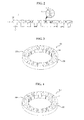
- FIG. 2 is an assembly view of FIG. 1
- FIG. 3 is a perspective view illustrating the stator core of FIG. 1 , which is bended and is cylindrically rolled, and as a fixing unit according to the first exemplary embodiment of the present disclosure
- FIG. 4 is a perspective view illustrating the stator core of FIG. 1 , which is bended and is cylindrically rolled, and as a fixing unit according to the second exemplary embodiment ofthe present disclosure
- FIG. 5 is a perspective view illustrating the stator core module of FIG. 1 , which is bended and is cylindrically rolled
- FIG. 6 is an enlarged view of the teeth for stator core module in FIG. 5 .
- the stator core of the present invention comprises the stator core module (1) composed of assembly with the stator core body (100), the first insulator (410), and the second insulator (420), and wound by the coil (C, referring FIG. 8 ), and further comprises the fixing units (200) (300) for fixing the bended stator core body (100) as a circular shape.
- the stator core body (100) is formed as one body by mold for plural teeth (110) to be formed protrusively at regular interval in the same direction.
- the stator core body (100) is formed as cylindrical shape in which both ends (101) (102) are combined by bending process for a designed section (A) of right and left around the teeth (110) as shown in FIG. 2 .
- the stator core body (100) has a hook unit (120) having complementary shape around the protrusion of the adjacent teeth (110) in order to maintain a cylindrical shape in the bending process.
- the hook unit (120) has a concavo and convex structure interlocked with each other.
- the hook protrusion (121) is formed at the one end, and the receptive groove (122) is formed at the other end of the hook unit (120).
- the edges of the hook protrusion (121) and the receptive groove (122) are rounded for smooth combination.
- the gapped groove (123) is formed at the position nearby the hook unit (12) to reduce an interference effect of each designed section (A) during the bending of stator core body (100).
- the gapped groove (123), as shown in FIG. 1 has a trench structure having a roughly circular cross section and one end is opened thus this opened end is connected with the hook unit (120).
- the fixing unit (200) is formed at the both ends of the stator core body (100) in order to fix the stator core body (100) as a cylindrical shape, and comprises the fixing protrusion (210) and the fixing groove (220).
- the fixing protrusion (210) is protrusively formed at the one end (101) of the stator core body (100), and is formed to have a roughly square cross section as shown, but it is not limited to the square cross section, further the cross section can have a circular or polygonal shape even though those are not shown.
- the fixing protrusion (210) can have whatever structures if the fixing protrusion (210) is hooked in the separation direction ofthe fixing groove (220).
- the fixing groove (220) is concavely formed as a complementary shape to the fixing protrusion (210) at the other end (102) of the stator core body (100).
- the fixing unit (200) configured in the same manner as above, is fixed by a sliding-fit assembly of the fixing protrusion (210) and the fixing groove (200), and the fixing unit (200) fixes the stator core body (100) as a cylindrical shape by press-in process of minimizing a tolerance between the fixing protrusion (210) and the fixing groove (200).
- the fixing unit (300) comprises, as shown in FIG. 4 and FIG. 5 , a pin groove (310) and a fixing pin (320).
- the pin groove (310) is formed at both ends of the stator core body (100), as shown, and comprises more than two hitching units (311) and an opening unit (312) connected with the hitching unit (311), and prevents the fixing pin (320) from being separated in the perpendicular direction to the direction (Arrow B direction in FIG. 5 ) of which the fixing pin (320) is inserted and assembled in the pin groove (310).
- the pin groove (310) is installed to have a mutually symmetrical shape at the both ends (101) (102) (Referring FIG. 1 ) ofthe stator core body (100).
- the fixing pin (320) has a complementary shape to a shape of the pin groove (310) to be inserted and assembled in the pin groove (310).
- the fixing pin (320) has a bilateral symmetrical shape because the pin groove (310) located at the both ends (101) (102) ofthe stator core body (100) has a mutually symmetrical shape.
- the fixing pin (320) is pressed and assembled in the parallel direction to the arrow B direction of FIG. 6 .
- the pin groove (310) is arranged as a "T” shape, and the fixing pin (320) fixedly inserted in a pair of the pin groove (310) is arranged as a "H" shape, but it is not limited to the described shapes, further the shapes can have whatever shapes if the shape can prevent the separation in the perpendicular direction to the described arrow B direction.
- each corner of the pin groove (310) and the fixing pin (320) are rounded, and are arranged as same thickness with the stator core body (100).
- the fixing unit (300) using the fixing pin (320) By means of the fixing unit (300) using the fixing pin (320), the combination and transportation for motor is easy and the loss of working following combination error of core unit can be reduced because the air gap of each split cores is minimized during the combination of stator core.
- the first insulator (410) and the second insulator (420), as shown in FIG. 1 , FIG. 2 , FIG. 7 , and FIG. 8 , are connected at the upper and the lower ofthe stator core body (100), and prevent a current flowing in the coil (C) wound in the teeth (110) from being transmitted to the stator core body (100).
- the first insulator (410) and the second insulator (420) are arranged as mutually complementary shapes, and assembled with the stator core body (100) at the same time.
- the first insulator (410) and the second insulator (420), as shown in FIG. 1 and FIG. 2 are formed as one body having a line shape by injection molding.
- the first simulator (410) and the second simulator (420) are arranged to be separated from each other by the section wrapping the teeth (110) during the bending process of the stator core body.
- the first insulator (410) and the second insulator (420), as shown in FIG. 1 and FIG. 2 have the bottleneck (411) (421) having within 0.5mm thickness nearby the position of the bending section of the stator core body (100), and the bottleneck (411) (421) is fractured by fatigue during the bending process of the stator core body (100).
- the first No.1 insulator (410a) and the second No.1 insulator (410b), which are attached each other when first created, can form neck unit (N) by separation as shown in FIG. 8 if the stator core module (1) is bended as cylindrical shape.
- stator core for motor for motor
- manufacturing method of stator core for motor will be described in detail according to an exemplary embodiment ofthe present disclosure.
- An object ofthe present invention is to form the stator core body (100), the first insulator (410), and the second insulator (420) as a line shape for the manufacturing of the stator core module (1), and is to form the temporarily assembled stator core module (1), as shown in FIG. 2 , by the combination of the stator core body (100), the first insulator (410), and the second insulator (420).
- one body by mold is formed for plural teeth protrusively at regular interval in the same direction.
- More than one stator core body preferably two stator core bodies (100) are formed by injection or sintering as cylindrical shape in which both ends are combined by bending process for a designed section of right and left around the teeth.
- the opposite surface of the teeth formed is configured to have a circular shape and have an arc shape by a constant interval (S10).
- the first insulator (410) and the second insulator (420) are integrally made by injection molding to have complementary shape to each other, and to wrap a part of stator core body (100) and one end surface of the plural teeth (110) simultaneously.
- the first insulator (410) and the second insulator (420) are made of synthetic resins often used as insulating material (S20).
- the line-shaped stator core module (1) is formed by the assembly with the stator core body (110), the first insulator (410), and the second insulator (420), which all are formed from the S10 stage and the S20 stage, in a line condition which is previous stage of bending.
- the coil (C, Referring FIG. 8 ) is wound on the teeth (110) insulated by the first insulator (410) and the second insulator (420) of the line-shaped stator core module (10) formed from the S30 stage.
- the described coiling more simple coiling can be done comparing to a coiling process that coils on the teeth of an integrated stator core of existing.
- the end of the teeth (110) has a small number of turns, and the other end has a large number of turns.
- stator core module (1) can be improved because it is possible to make a uniform distance (g) with the coil (C) on the adjacent teeth (110) after bending (S40).
- stator core module (1) coiled from the S40 stage, the stator core body (100), the first insulator (410), and the second insulator (420) is fixed by the fixing units (200) (300) arranged ate the both ends of the stator core body after bending the stator core body (100), the first insulator (410), and the second insulator (420) as a circular shape (S50).
- the stage of bending further comprises a stage (S51) of fixing for every teeth by the section successively through the hook unit (120), which is configured nearby the stator core body (100), and has complementary shape around the protrusion of the adjacent teeth, and a stage (S52) of forming the separated neck unit (N) (Referring FIG. 8 ) through the fatigue fracture, which is caused by bending, for the bottleneck (411) (421) of the first insulator (410) and the second insulator (420).
- the cylindrical-shaped stator core can be formed by combination with the another stator core module (1) made from the stage of S10 or S50.
- the cylindrical-shaped stator core body (100) is formed by the combination of the two semicircular-shaped stator core modules (1).
- the stator core body (100) is combined by using just one or two stator core module (1) because there is no difference with a conventional combination process using split core if the number of the stator core module (1) increases.
Landscapes
- Engineering & Computer Science (AREA)
- Power Engineering (AREA)
- Manufacturing & Machinery (AREA)
- Iron Core Of Rotating Electric Machines (AREA)
- Manufacture Of Motors, Generators (AREA)
Priority Applications (1)
| Application Number | Priority Date | Filing Date | Title |
|---|---|---|---|
| EP20177269.6A EP3723250B1 (de) | 2011-10-20 | 2012-08-06 | Statorkern für motor und herstellungsverfahren dafür |
Applications Claiming Priority (1)
| Application Number | Priority Date | Filing Date | Title |
|---|---|---|---|
| KR1020110107389A KR101876226B1 (ko) | 2011-10-20 | 2011-10-20 | 모터의 스테이터 코어 및 그 제조방법 |
Related Child Applications (2)
| Application Number | Title | Priority Date | Filing Date |
|---|---|---|---|
| EP20177269.6A Division EP3723250B1 (de) | 2011-10-20 | 2012-08-06 | Statorkern für motor und herstellungsverfahren dafür |
| EP20177269.6A Division-Into EP3723250B1 (de) | 2011-10-20 | 2012-08-06 | Statorkern für motor und herstellungsverfahren dafür |
Publications (3)
| Publication Number | Publication Date |
|---|---|
| EP2584680A2 true EP2584680A2 (de) | 2013-04-24 |
| EP2584680A3 EP2584680A3 (de) | 2017-06-28 |
| EP2584680B1 EP2584680B1 (de) | 2020-07-15 |
Family
ID=46679175
Family Applications (2)
| Application Number | Title | Priority Date | Filing Date |
|---|---|---|---|
| EP12179366.5A Active EP2584680B1 (de) | 2011-10-20 | 2012-08-06 | Statorkern für Motor und sein Herstellungsverfahren |
| EP20177269.6A Active EP3723250B1 (de) | 2011-10-20 | 2012-08-06 | Statorkern für motor und herstellungsverfahren dafür |
Family Applications After (1)
| Application Number | Title | Priority Date | Filing Date |
|---|---|---|---|
| EP20177269.6A Active EP3723250B1 (de) | 2011-10-20 | 2012-08-06 | Statorkern für motor und herstellungsverfahren dafür |
Country Status (4)
| Country | Link |
|---|---|
| US (2) | US9473005B2 (de) |
| EP (2) | EP2584680B1 (de) |
| JP (1) | JP6166025B2 (de) |
| KR (1) | KR101876226B1 (de) |
Cited By (3)
| Publication number | Priority date | Publication date | Assignee | Title |
|---|---|---|---|---|
| CN104362810A (zh) * | 2014-10-31 | 2015-02-18 | 广东威灵电机制造有限公司 | 定子冲片的制造方法 |
| CN104578613A (zh) * | 2014-12-25 | 2015-04-29 | 广东威灵电机制造有限公司 | 定子的制造方法 |
| EP3035491A4 (de) * | 2013-11-08 | 2018-05-30 | Samsung Electronics Co., Ltd. | Motor, herstellungsverfahren dafür und waschmaschine |
Families Citing this family (16)
| Publication number | Priority date | Publication date | Assignee | Title |
|---|---|---|---|---|
| DE102011085636A1 (de) * | 2011-11-02 | 2013-05-02 | Hamilton Bonaduz Ag | Linearmotor mit mehreren Sensoreinheiten und modularem Statoraufbau |
| US9143015B2 (en) | 2012-05-23 | 2015-09-22 | Black & Decker Inc. | Brush holder for a brush assembly for a power tool motor |
| WO2014203849A1 (ja) * | 2013-06-21 | 2014-12-24 | 日本電産サーボ株式会社 | 回転電機及び回転電機の製造方法 |
| JP5980185B2 (ja) * | 2013-09-20 | 2016-08-31 | 日本電産テクノモータ株式会社 | 樹脂モールドステータおよびその製造方法 |
| DE112013007578T5 (de) * | 2013-11-08 | 2016-08-18 | Mitsubishi Electric Corporation | Stator einer rotierenden elektrischen Maschine und rotierendeelektrische Maschine |
| KR102604381B1 (ko) * | 2016-07-07 | 2023-11-21 | 엘지이노텍 주식회사 | 스테이터 유닛, 스테이터 및 이를 포함하는 모터 |
| FR3072517B1 (fr) * | 2017-10-17 | 2020-12-18 | Moving Magnet Tech | Machine electrique toroidale polyphasee |
| US11456629B2 (en) * | 2017-12-07 | 2022-09-27 | Kyocera Industrial Tools Corporation | Stator with divided cores connected circumferentially |
| CN108270330B (zh) * | 2017-12-29 | 2024-10-22 | 日本电产芝浦(浙江)有限公司 | 定子铁芯弯曲设备、定子铁芯弯曲方法以及定子铁芯 |
| EP3745559B1 (de) * | 2019-05-27 | 2022-03-09 | Magnax Bv | Stator für eine axialflussmaschine |
| KR102784711B1 (ko) * | 2020-05-21 | 2025-03-21 | 엘지전자 주식회사 | 전동기 및 이를 구비한 청소기, 전동기의 제조방법 |
| JP7637495B2 (ja) * | 2020-11-20 | 2025-02-28 | ミネベアミツミ株式会社 | モータ |
| JP7705237B2 (ja) * | 2020-11-20 | 2025-07-09 | ミネベアミツミ株式会社 | モータ |
| DE102021106186A1 (de) * | 2021-03-15 | 2022-09-15 | Ebm-Papst Mulfingen Gmbh & Co. Kg | Modular aufgebautes, segmentiertes Statorpaket |
| IT202200014590A1 (it) * | 2022-07-12 | 2024-01-12 | Marelli Europe Spa | Statore con avvolgimento a barre e raffreddamento a fluido per una macchina elettrica rotante |
| JP7814336B2 (ja) * | 2023-03-01 | 2026-02-16 | 三菱電機株式会社 | 固定子の製造方法、電動機の製造方法 |
Citations (1)
| Publication number | Priority date | Publication date | Assignee | Title |
|---|---|---|---|---|
| KR20080078944A (ko) | 2007-02-26 | 2008-08-29 | 엘지전자 주식회사 | 모터코어 및 그 제조방법 |
Family Cites Families (20)
| Publication number | Priority date | Publication date | Assignee | Title |
|---|---|---|---|---|
| US2502185A (en) * | 1949-03-29 | 1950-03-28 | Gen Electric | Stator for universal electric motors |
| US4366198A (en) * | 1981-03-24 | 1982-12-28 | Rca Corporation | Sheet material separation construction |
| JPH0348343U (de) * | 1989-09-18 | 1991-05-09 | ||
| JPH069349U (ja) * | 1991-09-05 | 1994-02-04 | 日本電産株式会社 | 電動機の固定子鉄心 |
| JP2933807B2 (ja) * | 1993-08-23 | 1999-08-16 | 株式会社三協精機製作所 | 回転電機の鉄心 |
| JP3017085B2 (ja) * | 1995-11-02 | 2000-03-06 | 三菱電機株式会社 | 回転電機及びその製造方法 |
| JP3680482B2 (ja) | 1997-03-28 | 2005-08-10 | 松下電器産業株式会社 | 電動機の固定子構成部材、電動機の固定子、電動機の製造方法 |
| JP2000014057A (ja) | 1998-06-18 | 2000-01-14 | Nippon Densan Corp | 回転機の電機子構造及びその製造方法 |
| JP3451263B2 (ja) | 1998-08-28 | 2003-09-29 | 三菱電機株式会社 | ステータ |
| JP2001045684A (ja) | 1999-07-30 | 2001-02-16 | Hitachi Ltd | 電動機固定子鉄心の製造方法 |
| JP2001136700A (ja) * | 1999-11-02 | 2001-05-18 | Mitsubishi Electric Corp | 固定子および固定子の製造方法 |
| JP2001211574A (ja) | 2000-01-20 | 2001-08-03 | Techno Excel Co Ltd | 電動機の固定子鉄心 |
| JP3674599B2 (ja) | 2002-05-02 | 2005-07-20 | 日本電産シバウラ株式会社 | 電動機鉄心、電動機及び電動機鉄心の製造方法 |
| KR100454556B1 (ko) * | 2002-05-09 | 2004-11-05 | 주식회사 미크로닉 | 세그먼트형 스테이터 코어를 이용한 비엘디씨 모터용스테이터 및 그의 제조방법과 비엘디씨 모터 |
| US6919665B2 (en) * | 2003-09-30 | 2005-07-19 | Nidec Shibaura Corporation | Stator core, an electric motor in which it is utilized, and method of manufacturing a stator core |
| JP4150397B2 (ja) | 2005-11-16 | 2008-09-17 | 株式会社三井ハイテック | 積層鉄心及びその製造方法 |
| JP2007151312A (ja) | 2005-11-29 | 2007-06-14 | Fujitsu General Ltd | 誘導電動機 |
| JP4711877B2 (ja) * | 2006-04-13 | 2011-06-29 | 株式会社山田製作所 | 焼結コア連結構造の製造法及びその焼結コア連結構造 |
| JP4948474B2 (ja) * | 2008-05-16 | 2012-06-06 | 株式会社富士通ゼネラル | 電動機 |
| JP5601799B2 (ja) | 2009-07-10 | 2014-10-08 | パナソニック株式会社 | ステータおよびステータの製造方法 |
-
2011
- 2011-10-20 KR KR1020110107389A patent/KR101876226B1/ko not_active Expired - Fee Related
-
2012
- 2012-08-06 US US13/567,835 patent/US9473005B2/en active Active
- 2012-08-06 EP EP12179366.5A patent/EP2584680B1/de active Active
- 2012-08-06 EP EP20177269.6A patent/EP3723250B1/de active Active
- 2012-08-31 JP JP2012190992A patent/JP6166025B2/ja active Active
-
2016
- 2016-08-25 US US15/247,312 patent/US9755488B2/en active Active
Patent Citations (1)
| Publication number | Priority date | Publication date | Assignee | Title |
|---|---|---|---|---|
| KR20080078944A (ko) | 2007-02-26 | 2008-08-29 | 엘지전자 주식회사 | 모터코어 및 그 제조방법 |
Cited By (6)
| Publication number | Priority date | Publication date | Assignee | Title |
|---|---|---|---|---|
| EP3035491A4 (de) * | 2013-11-08 | 2018-05-30 | Samsung Electronics Co., Ltd. | Motor, herstellungsverfahren dafür und waschmaschine |
| US10673289B2 (en) | 2013-11-08 | 2020-06-02 | Samsung Electronics Co., Ltd. | Motor with stiffened stator core, manufacturing method thereof, and washing machine including the motor |
| CN104362810A (zh) * | 2014-10-31 | 2015-02-18 | 广东威灵电机制造有限公司 | 定子冲片的制造方法 |
| CN104362810B (zh) * | 2014-10-31 | 2017-06-13 | 广东威灵电机制造有限公司 | 定子冲片的制造方法 |
| CN104578613A (zh) * | 2014-12-25 | 2015-04-29 | 广东威灵电机制造有限公司 | 定子的制造方法 |
| CN104578613B (zh) * | 2014-12-25 | 2017-09-19 | 广东威灵电机制造有限公司 | 定子的制造方法 |
Also Published As
| Publication number | Publication date |
|---|---|
| US20130099604A1 (en) | 2013-04-25 |
| US9755488B2 (en) | 2017-09-05 |
| JP6166025B2 (ja) | 2017-07-19 |
| KR20130043343A (ko) | 2013-04-30 |
| KR101876226B1 (ko) | 2018-07-09 |
| EP3723250B1 (de) | 2021-10-20 |
| US20160365778A1 (en) | 2016-12-15 |
| EP3723250A1 (de) | 2020-10-14 |
| US9473005B2 (en) | 2016-10-18 |
| JP2013090561A (ja) | 2013-05-13 |
| EP2584680B1 (de) | 2020-07-15 |
| EP2584680A3 (de) | 2017-06-28 |
Similar Documents
| Publication | Publication Date | Title |
|---|---|---|
| EP2584680B1 (de) | Statorkern für Motor und sein Herstellungsverfahren | |
| CN101621221B (zh) | 电动机及该电动机的制造方法 | |
| US9343221B2 (en) | Resin-mold core and reactor using the same | |
| US9705386B2 (en) | Laminated core for motor and method for manufacturing the same | |
| KR101345029B1 (ko) | 회전 전기의 몰드 스테이터의 제조 방법 | |
| JP2013197567A (ja) | リアクトル及びその製造方法 | |
| US20160036187A1 (en) | Manufacturing method of bus bar unit | |
| US10594174B2 (en) | Tool and method for use in assembling a stator assembly of an electric machine | |
| KR20140109997A (ko) | 코일의 제조 방법 | |
| JP5505661B2 (ja) | 電動機の製造方法 | |
| CN107710557A (zh) | 电动机的定子 | |
| JP5212129B2 (ja) | 積層コアの製造方法及びその製造治具 | |
| CN103053099A (zh) | 电机的定子 | |
| KR101958648B1 (ko) | 변압기용 평판형 2차 코일 소자 어셈블리 제조 방법 | |
| WO2015087128A2 (en) | Insulator and stator | |
| EP2711948A2 (de) | Verfahren zur herstellung einer laminierten spule in form einer acht | |
| US20070194652A1 (en) | Dynamoelectric stator core and method for manufacture thereof | |
| JP5860767B2 (ja) | コイルの製造方法 | |
| KR102173625B1 (ko) | 3 분할 적층 코어로 이루어진 모터 코어 | |
| JP2021086953A (ja) | コイルアッシー及びこれを備えたトランス | |
| JP2007166759A (ja) | 固定子とその製造方法およびこの固定子を用いた電動機 | |
| JP6432431B2 (ja) | コイル部品およびコイル部品の成形方法 | |
| JP2013251997A (ja) | コイルの製造方法 | |
| JP2021012953A (ja) | リアクトル用ボビン、リアクトルおよびリアクトルの製造方法 | |
| CN112185669A (zh) | 电抗器用骨架、电抗器以及电抗器的制造方法 |
Legal Events
| Date | Code | Title | Description |
|---|---|---|---|
| PUAI | Public reference made under article 153(3) epc to a published international application that has entered the european phase |
Free format text: ORIGINAL CODE: 0009012 |
|
| AK | Designated contracting states |
Kind code of ref document: A2 Designated state(s): AL AT BE BG CH CY CZ DE DK EE ES FI FR GB GR HR HU IE IS IT LI LT LU LV MC MK MT NL NO PL PT RO RS SE SI SK SM TR |
|
| AX | Request for extension of the european patent |
Extension state: BA ME |
|
| RAP1 | Party data changed (applicant data changed or rights of an application transferred) |
Owner name: LG INNOTEK CO., LTD. |
|
| PUAL | Search report despatched |
Free format text: ORIGINAL CODE: 0009013 |
|
| AK | Designated contracting states |
Kind code of ref document: A3 Designated state(s): AL AT BE BG CH CY CZ DE DK EE ES FI FR GB GR HR HU IE IS IT LI LT LU LV MC MK MT NL NO PL PT RO RS SE SI SK SM TR |
|
| AX | Request for extension of the european patent |
Extension state: BA ME |
|
| RIC1 | Information provided on ipc code assigned before grant |
Ipc: H02K 15/02 20060101AFI20170524BHEP Ipc: H02K 1/14 20060101ALI20170524BHEP Ipc: H02K 3/34 20060101ALI20170524BHEP |
|
| STAA | Information on the status of an ep patent application or granted ep patent |
Free format text: STATUS: REQUEST FOR EXAMINATION WAS MADE |
|
| 17P | Request for examination filed |
Effective date: 20171205 |
|
| RBV | Designated contracting states (corrected) |
Designated state(s): AL AT BE BG CH CY CZ DE DK EE ES FI FR GB GR HR HU IE IS IT LI LT LU LV MC MK MT NL NO PL PT RO RS SE SI SK SM TR |
|
| STAA | Information on the status of an ep patent application or granted ep patent |
Free format text: STATUS: EXAMINATION IS IN PROGRESS |
|
| 17Q | First examination report despatched |
Effective date: 20181122 |
|
| GRAP | Despatch of communication of intention to grant a patent |
Free format text: ORIGINAL CODE: EPIDOSNIGR1 |
|
| STAA | Information on the status of an ep patent application or granted ep patent |
Free format text: STATUS: GRANT OF PATENT IS INTENDED |
|
| INTG | Intention to grant announced |
Effective date: 20200128 |
|
| GRAS | Grant fee paid |
Free format text: ORIGINAL CODE: EPIDOSNIGR3 |
|
| GRAA | (expected) grant |
Free format text: ORIGINAL CODE: 0009210 |
|
| STAA | Information on the status of an ep patent application or granted ep patent |
Free format text: STATUS: THE PATENT HAS BEEN GRANTED |
|
| AK | Designated contracting states |
Kind code of ref document: B1 Designated state(s): AL AT BE BG CH CY CZ DE DK EE ES FI FR GB GR HR HU IE IS IT LI LT LU LV MC MK MT NL NO PL PT RO RS SE SI SK SM TR |
|
| REG | Reference to a national code |
Ref country code: CH Ref legal event code: EP Ref country code: GB Ref legal event code: FG4D |
|
| REG | Reference to a national code |
Ref country code: IE Ref legal event code: FG4D |
|
| REG | Reference to a national code |
Ref country code: DE Ref legal event code: R096 Ref document number: 602012071234 Country of ref document: DE |
|
| REG | Reference to a national code |
Ref country code: AT Ref legal event code: REF Ref document number: 1292076 Country of ref document: AT Kind code of ref document: T Effective date: 20200815 |
|
| REG | Reference to a national code |
Ref country code: LT Ref legal event code: MG4D |
|
| REG | Reference to a national code |
Ref country code: AT Ref legal event code: MK05 Ref document number: 1292076 Country of ref document: AT Kind code of ref document: T Effective date: 20200715 |
|
| REG | Reference to a national code |
Ref country code: NL Ref legal event code: MP Effective date: 20200715 |
|
| PG25 | Lapsed in a contracting state [announced via postgrant information from national office to epo] |
Ref country code: NO Free format text: LAPSE BECAUSE OF FAILURE TO SUBMIT A TRANSLATION OF THE DESCRIPTION OR TO PAY THE FEE WITHIN THE PRESCRIBED TIME-LIMIT Effective date: 20201015 Ref country code: GR Free format text: LAPSE BECAUSE OF FAILURE TO SUBMIT A TRANSLATION OF THE DESCRIPTION OR TO PAY THE FEE WITHIN THE PRESCRIBED TIME-LIMIT Effective date: 20201016 Ref country code: SE Free format text: LAPSE BECAUSE OF FAILURE TO SUBMIT A TRANSLATION OF THE DESCRIPTION OR TO PAY THE FEE WITHIN THE PRESCRIBED TIME-LIMIT Effective date: 20200715 Ref country code: BG Free format text: LAPSE BECAUSE OF FAILURE TO SUBMIT A TRANSLATION OF THE DESCRIPTION OR TO PAY THE FEE WITHIN THE PRESCRIBED TIME-LIMIT Effective date: 20201015 Ref country code: HR Free format text: LAPSE BECAUSE OF FAILURE TO SUBMIT A TRANSLATION OF THE DESCRIPTION OR TO PAY THE FEE WITHIN THE PRESCRIBED TIME-LIMIT Effective date: 20200715 Ref country code: AT Free format text: LAPSE BECAUSE OF FAILURE TO SUBMIT A TRANSLATION OF THE DESCRIPTION OR TO PAY THE FEE WITHIN THE PRESCRIBED TIME-LIMIT Effective date: 20200715 Ref country code: FI Free format text: LAPSE BECAUSE OF FAILURE TO SUBMIT A TRANSLATION OF THE DESCRIPTION OR TO PAY THE FEE WITHIN THE PRESCRIBED TIME-LIMIT Effective date: 20200715 Ref country code: LT Free format text: LAPSE BECAUSE OF FAILURE TO SUBMIT A TRANSLATION OF THE DESCRIPTION OR TO PAY THE FEE WITHIN THE PRESCRIBED TIME-LIMIT Effective date: 20200715 Ref country code: PT Free format text: LAPSE BECAUSE OF FAILURE TO SUBMIT A TRANSLATION OF THE DESCRIPTION OR TO PAY THE FEE WITHIN THE PRESCRIBED TIME-LIMIT Effective date: 20201116 Ref country code: ES Free format text: LAPSE BECAUSE OF FAILURE TO SUBMIT A TRANSLATION OF THE DESCRIPTION OR TO PAY THE FEE WITHIN THE PRESCRIBED TIME-LIMIT Effective date: 20200715 |
|
| PG25 | Lapsed in a contracting state [announced via postgrant information from national office to epo] |
Ref country code: LV Free format text: LAPSE BECAUSE OF FAILURE TO SUBMIT A TRANSLATION OF THE DESCRIPTION OR TO PAY THE FEE WITHIN THE PRESCRIBED TIME-LIMIT Effective date: 20200715 Ref country code: PL Free format text: LAPSE BECAUSE OF FAILURE TO SUBMIT A TRANSLATION OF THE DESCRIPTION OR TO PAY THE FEE WITHIN THE PRESCRIBED TIME-LIMIT Effective date: 20200715 Ref country code: RS Free format text: LAPSE BECAUSE OF FAILURE TO SUBMIT A TRANSLATION OF THE DESCRIPTION OR TO PAY THE FEE WITHIN THE PRESCRIBED TIME-LIMIT Effective date: 20200715 Ref country code: IS Free format text: LAPSE BECAUSE OF FAILURE TO SUBMIT A TRANSLATION OF THE DESCRIPTION OR TO PAY THE FEE WITHIN THE PRESCRIBED TIME-LIMIT Effective date: 20201115 |
|
| PG25 | Lapsed in a contracting state [announced via postgrant information from national office to epo] |
Ref country code: NL Free format text: LAPSE BECAUSE OF FAILURE TO SUBMIT A TRANSLATION OF THE DESCRIPTION OR TO PAY THE FEE WITHIN THE PRESCRIBED TIME-LIMIT Effective date: 20200715 |
|
| REG | Reference to a national code |
Ref country code: CH Ref legal event code: PL |
|
| REG | Reference to a national code |
Ref country code: DE Ref legal event code: R097 Ref document number: 602012071234 Country of ref document: DE |
|
| PG25 | Lapsed in a contracting state [announced via postgrant information from national office to epo] |
Ref country code: MC Free format text: LAPSE BECAUSE OF FAILURE TO SUBMIT A TRANSLATION OF THE DESCRIPTION OR TO PAY THE FEE WITHIN THE PRESCRIBED TIME-LIMIT Effective date: 20200715 Ref country code: LU Free format text: LAPSE BECAUSE OF NON-PAYMENT OF DUE FEES Effective date: 20200806 Ref country code: RO Free format text: LAPSE BECAUSE OF FAILURE TO SUBMIT A TRANSLATION OF THE DESCRIPTION OR TO PAY THE FEE WITHIN THE PRESCRIBED TIME-LIMIT Effective date: 20200715 Ref country code: SM Free format text: LAPSE BECAUSE OF FAILURE TO SUBMIT A TRANSLATION OF THE DESCRIPTION OR TO PAY THE FEE WITHIN THE PRESCRIBED TIME-LIMIT Effective date: 20200715 Ref country code: LI Free format text: LAPSE BECAUSE OF NON-PAYMENT OF DUE FEES Effective date: 20200831 Ref country code: IT Free format text: LAPSE BECAUSE OF FAILURE TO SUBMIT A TRANSLATION OF THE DESCRIPTION OR TO PAY THE FEE WITHIN THE PRESCRIBED TIME-LIMIT Effective date: 20200715 Ref country code: EE Free format text: LAPSE BECAUSE OF FAILURE TO SUBMIT A TRANSLATION OF THE DESCRIPTION OR TO PAY THE FEE WITHIN THE PRESCRIBED TIME-LIMIT Effective date: 20200715 Ref country code: CZ Free format text: LAPSE BECAUSE OF FAILURE TO SUBMIT A TRANSLATION OF THE DESCRIPTION OR TO PAY THE FEE WITHIN THE PRESCRIBED TIME-LIMIT Effective date: 20200715 Ref country code: CH Free format text: LAPSE BECAUSE OF NON-PAYMENT OF DUE FEES Effective date: 20200831 Ref country code: DK Free format text: LAPSE BECAUSE OF FAILURE TO SUBMIT A TRANSLATION OF THE DESCRIPTION OR TO PAY THE FEE WITHIN THE PRESCRIBED TIME-LIMIT Effective date: 20200715 |
|
| PLBE | No opposition filed within time limit |
Free format text: ORIGINAL CODE: 0009261 |
|
| STAA | Information on the status of an ep patent application or granted ep patent |
Free format text: STATUS: NO OPPOSITION FILED WITHIN TIME LIMIT |
|
| REG | Reference to a national code |
Ref country code: BE Ref legal event code: MM Effective date: 20200831 |
|
| PG25 | Lapsed in a contracting state [announced via postgrant information from national office to epo] |
Ref country code: AL Free format text: LAPSE BECAUSE OF FAILURE TO SUBMIT A TRANSLATION OF THE DESCRIPTION OR TO PAY THE FEE WITHIN THE PRESCRIBED TIME-LIMIT Effective date: 20200715 |
|
| 26N | No opposition filed |
Effective date: 20210416 |
|
| GBPC | Gb: european patent ceased through non-payment of renewal fee |
Effective date: 20201015 |
|
| PG25 | Lapsed in a contracting state [announced via postgrant information from national office to epo] |
Ref country code: SK Free format text: LAPSE BECAUSE OF FAILURE TO SUBMIT A TRANSLATION OF THE DESCRIPTION OR TO PAY THE FEE WITHIN THE PRESCRIBED TIME-LIMIT Effective date: 20200715 |
|
| PG25 | Lapsed in a contracting state [announced via postgrant information from national office to epo] |
Ref country code: BE Free format text: LAPSE BECAUSE OF NON-PAYMENT OF DUE FEES Effective date: 20200831 Ref country code: SI Free format text: LAPSE BECAUSE OF FAILURE TO SUBMIT A TRANSLATION OF THE DESCRIPTION OR TO PAY THE FEE WITHIN THE PRESCRIBED TIME-LIMIT Effective date: 20200715 Ref country code: GB Free format text: LAPSE BECAUSE OF NON-PAYMENT OF DUE FEES Effective date: 20201015 Ref country code: IE Free format text: LAPSE BECAUSE OF NON-PAYMENT OF DUE FEES Effective date: 20200806 |
|
| PG25 | Lapsed in a contracting state [announced via postgrant information from national office to epo] |
Ref country code: TR Free format text: LAPSE BECAUSE OF FAILURE TO SUBMIT A TRANSLATION OF THE DESCRIPTION OR TO PAY THE FEE WITHIN THE PRESCRIBED TIME-LIMIT Effective date: 20200715 Ref country code: MT Free format text: LAPSE BECAUSE OF FAILURE TO SUBMIT A TRANSLATION OF THE DESCRIPTION OR TO PAY THE FEE WITHIN THE PRESCRIBED TIME-LIMIT Effective date: 20200715 Ref country code: CY Free format text: LAPSE BECAUSE OF FAILURE TO SUBMIT A TRANSLATION OF THE DESCRIPTION OR TO PAY THE FEE WITHIN THE PRESCRIBED TIME-LIMIT Effective date: 20200715 |
|
| PG25 | Lapsed in a contracting state [announced via postgrant information from national office to epo] |
Ref country code: MK Free format text: LAPSE BECAUSE OF FAILURE TO SUBMIT A TRANSLATION OF THE DESCRIPTION OR TO PAY THE FEE WITHIN THE PRESCRIBED TIME-LIMIT Effective date: 20200715 |
|
| PGFP | Annual fee paid to national office [announced via postgrant information from national office to epo] |
Ref country code: DE Payment date: 20240722 Year of fee payment: 13 |
|
| PGFP | Annual fee paid to national office [announced via postgrant information from national office to epo] |
Ref country code: FR Payment date: 20240723 Year of fee payment: 13 |
|
| REG | Reference to a national code |
Ref country code: DE Ref legal event code: R119 Ref document number: 602012071234 Country of ref document: DE |