EP2584714A2 - Verfahren zur übertragung eines pufferstatusberichts von einem endgerät in einem drahtlosen kommunikationssystem und vorrichtung dafür - Google Patents
Verfahren zur übertragung eines pufferstatusberichts von einem endgerät in einem drahtlosen kommunikationssystem und vorrichtung dafür Download PDFInfo
- Publication number
- EP2584714A2 EP2584714A2 EP11795968.4A EP11795968A EP2584714A2 EP 2584714 A2 EP2584714 A2 EP 2584714A2 EP 11795968 A EP11795968 A EP 11795968A EP 2584714 A2 EP2584714 A2 EP 2584714A2
- Authority
- EP
- European Patent Office
- Prior art keywords
- buffer size
- buffer
- status report
- user equipment
- specific value
- Prior art date
- Legal status (The legal status is an assumption and is not a legal conclusion. Google has not performed a legal analysis and makes no representation as to the accuracy of the status listed.)
- Granted
Links
Images



Classifications
-
- H—ELECTRICITY
- H04—ELECTRIC COMMUNICATION TECHNIQUE
- H04W—WIRELESS COMMUNICATION NETWORKS
- H04W28/00—Network traffic management; Network resource management
- H04W28/02—Traffic management, e.g. flow control or congestion control
- H04W28/0278—Traffic management, e.g. flow control or congestion control using buffer status reports
-
- H—ELECTRICITY
- H04—ELECTRIC COMMUNICATION TECHNIQUE
- H04W—WIRELESS COMMUNICATION NETWORKS
- H04W24/00—Supervisory, monitoring or testing arrangements
- H04W24/10—Scheduling measurement reports ; Arrangements for measurement reports
-
- H—ELECTRICITY
- H04—ELECTRIC COMMUNICATION TECHNIQUE
- H04W—WIRELESS COMMUNICATION NETWORKS
- H04W72/00—Local resource management
- H04W72/20—Control channels or signalling for resource management
- H04W72/21—Control channels or signalling for resource management in the uplink direction of a wireless link, i.e. towards the network
-
- H—ELECTRICITY
- H04—ELECTRIC COMMUNICATION TECHNIQUE
- H04L—TRANSMISSION OF DIGITAL INFORMATION, e.g. TELEGRAPHIC COMMUNICATION
- H04L5/00—Arrangements affording multiple use of the transmission path
- H04L5/0001—Arrangements for dividing the transmission path
- H04L5/0003—Two-dimensional division
- H04L5/0005—Time-frequency
- H04L5/0007—Time-frequency the frequencies being orthogonal, e.g. OFDM(A) or DMT
- H04L5/001—Time-frequency the frequencies being orthogonal, e.g. OFDM(A) or DMT the frequencies being arranged in component carriers
-
- H—ELECTRICITY
- H04—ELECTRIC COMMUNICATION TECHNIQUE
- H04L—TRANSMISSION OF DIGITAL INFORMATION, e.g. TELEGRAPHIC COMMUNICATION
- H04L5/00—Arrangements affording multiple use of the transmission path
- H04L5/0001—Arrangements for dividing the transmission path
- H04L5/0014—Three-dimensional division
- H04L5/0023—Time-frequency-space
-
- H—ELECTRICITY
- H04—ELECTRIC COMMUNICATION TECHNIQUE
- H04L—TRANSMISSION OF DIGITAL INFORMATION, e.g. TELEGRAPHIC COMMUNICATION
- H04L5/00—Arrangements affording multiple use of the transmission path
- H04L5/0091—Signalling for the administration of the divided path, e.g. signalling of configuration information
- H04L5/0096—Indication of changes in allocation
- H04L5/0098—Signalling of the activation or deactivation of component carriers, subcarriers or frequency bands
-
- H—ELECTRICITY
- H04—ELECTRIC COMMUNICATION TECHNIQUE
- H04W—WIRELESS COMMUNICATION NETWORKS
- H04W72/00—Local resource management
- H04W72/12—Wireless traffic scheduling
- H04W72/1221—Wireless traffic scheduling based on age of data to be sent
Definitions
- the present invention relates to a wireless communication system, and more particularly, to a method for transmitting buffer status report from a user equipment in a wireless communication system and an apparatus therefor.
- a 3 rd generation partnership project long term evolution (3GPP LTE) (hereinafter, referred to as 'LTE') communication system which is an example of a mobile communication system to which the present invention can be applied will be described in brief.
- 3GPP LTE 3 rd generation partnership project long term evolution
- FIG. 1 is a diagram illustrating a network structure of an Evolved Universal Mobile Telecommunications System (E-UMTS) which is an example of a mobile communication system.
- E-UMTS Evolved Universal Mobile Telecommunications System
- 3GPP 3rd Generation Partnership Project
- LTE Long Term Evolution
- the E-UMTS includes a User Equipment (UE) 120, base stations (eNode B and eNB) 110a and 110b, and an Access Gateway (AG) which is located at an end of a network (E-UTRAN) and connected to an external network.
- UE User Equipment
- base stations eNode B and eNB
- AG Access Gateway
- the base stations may simultaneously transmit multiple data streams for a broadcast service, a multicast service and/or a unicast service.
- One or more cells may exist for one base station.
- One cell is set to one of bandwidths of 1.25, 2.5, 5, 10, and 20MHz to provide a downlink or uplink transport service to several user equipments. Different cells may be set to provide different bandwidths.
- one base station controls data transmission and reception for a plurality of user equipments. The base station transmits downlink (DL) scheduling information of downlink data to the corresponding user equipment to notify the corresponding user equipment of time and frequency domains to which data will be transmitted and information related to encoding, data size, and hybrid automatic repeat and request (HARQ).
- DL downlink
- HARQ hybrid automatic repeat and request
- the base station transmits uplink (UL) scheduling information of uplink data to the corresponding user equipment to notify the corresponding user equipment of time and frequency domains that can be used by the corresponding user equipment, and information related to encoding, data size, and HARQ.
- UL uplink
- An interface for transmitting user traffic or control traffic can be used between the base stations.
- An interface for transmitting user traffic or control traffic may be used between the base stations.
- a Core Network (CN) may include the AG and a network node or the like for user registration of the user equipment UE.
- the AG manages mobility of the user equipment UE on a Tracking Area (TA) basis, wherein one TA includes a plurality of cells.
- TA Tracking Area
- LTE-Advanced LTE-Advanced
- LTE-A LTE-Advanced
- carrier aggregation aims to use a plurality of frequency blocks as one great logical frequency band.
- a bandwidth of each frequency block may be defined based on a bandwidth of a system block used in the LTE system.
- Each frequency block is transmitted using a component carrier.
- an object of the present invention devised to solve the conventional problem is to provide a method for transmitting buffer status report from a user equipment in a wireless communication system and an apparatus therefor.
- a method for transmitting a buffer status report from a user equipment in a wireless communication system comprises the steps of generating buffer status report information; and transmitting the buffer status report information to a base station, wherein the buffer status report information includes a first field including a plurality of indicators and at least one second field indicating a buffer size index, wherein each of the plurality of indicators indicates the presence or absence of the second field corresponding to each of at least one logical channel group (LCG).
- LCG logical channel group
- the buffer status report information includes at least one third field corresponding to each of the at least one second field, and each of the at least one third field includes an identifier of a buffer size table referred to determine the buffer size index included in the at least one second field.
- each of the at least one third field may indicate whether buffer size indicated by a corresponding second field is more than a specific value.
- the buffer size index is determined by referring to a first buffer size table, which quantizes buffer size less than the specific value, and if the buffer size of the corresponding logical channel group is more than the specific value, the buffer size index is determined by referring to a second buffer size table, which quantizes buffer size more than the specific value.
- a method for transmitting a buffer status report from a user equipment in a wireless communication system comprises the steps of generating buffer status report information including buffer size information; and transmitting the buffer status report information to a base station, wherein the buffer status report information includes a buffer size index and an identifier of a buffer size table, which is referred to determine the buffer size index.
- the buffer status report information includes identifier information of a logical channel group (LCG) corresponding to the buffer size information.
- LCG logical channel group
- the buffer size index is determined by referring to a first buffer size table, which quantizes buffer size less than the specific value, and if the buffer size of the logical channel group is more than the specific value, the buffer size index is determined by referring to a second buffer size table, which quantizes buffer size more than the specific value.
- a method for transmitting a buffer status report from a user equipment in a wireless communication system comprises the steps of generating buffer status report information; and transmitting the buffer status report information to a base station, wherein the buffer status report information includes buffer size information configured to correspond to each of at least one logical channel group (LCG) in the order of index of the at least one logical channel group, and the buffer size information includes a buffer size index corresponding to each of the at least one logical channel group and an identifier of a buffer size table referred to determine the buffer size index.
- LCG logical channel group
- the specific value is preferably 150 kbytes.
- the user equipment may effectively transmit a buffer status report to the base station.
- FIG. 1 is a diagram illustrating a network structure of an Evolved Universal Mobile Telecommunications System (E-UMTS), which is an example of a wireless communication system;
- E-UMTS Evolved Universal Mobile Telecommunications System
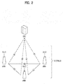
- FIG. 2 is a diagram illustrating a network structure of an evolved universal terrestrial radio access network (E-UTRAN);
- E-UTRAN evolved universal terrestrial radio access network
- FIG. 3 is a diagram illustrating structures of a control plane and a user plane of a radio interface protocol between a user equipment and an E-UTRAN based on the 3GPP radio access network standard;
- FIG. 4 is a diagram illustrating physical channels used in a 3GPP system and a general method for transmitting a signal using the physical channels;
- FIG. 5 is a diagram illustrating a structure of a radio frame used in an LTE system
- FIG. 6 is a conceptional diagram illustrating a carrier aggregation scheme
- FIG. 7 is a diagram illustrating an example of a buffer status report (BSR) defined in an LTE system
- FIG. 8 is a diagram illustrating a structure of a MAC subheader defined in an LTE system
- FIG. 9 is a diagram illustrating a MAC subheader and a MAC CE format of a short BSR-CA according to the embodiment of the present invention.
- FIG. 10 is a diagram illustrating a MAC subheader and a MAC CE format of a long BSR-CA according to the embodiment of the present invention.
- FIG. 11 is another diagram illustrating a MAC subheader and a MAC CE format of a short BSR-CA according to the embodiment of the present invention.
- FIG. 12 is a block diagram illustrating a communication apparatus according to the embodiment of the present invention.
- the embodiment of the present invention will be described based on the LTE system and the LTE-A system in this specification, the LTE system and the LTE-A system are only exemplary, and the embodiment of the present invention may be applied to all communication systems corresponding to the aforementioned definition. Also, although the embodiment of the present invention will be described based on an FDD mode in this specification, the FDD mode is only exemplary, and the embodiment of the present invention may easily be applied to an H-FDD mode or a TDD mode.
- FIG. 2 is a diagram illustrating a network structure of an Evolved Universal Terrestrial Radio Access Network (E-UTRAN) which is an example of a mobile communication system.
- E-UTRAN Evolved Universal Terrestrial Radio Access Network
- the E-UTRAN system is an evolved version of the conventional UTRAN system.
- the E-UTRAN includes cells (eNBs), which are connected with each other through an interface X2. Also, each of the cells is connected with a user equipment (UE) through a radio interface and connected with an evolved packet core (EPC) through an interface S1.
- UE user equipment
- EPC evolved packet core
- the EPC includes a mobility management entity (MME), a serving-gateway (S-GW), and a packet data network-gateway (PDN-GW).
- MME mobility management entity
- S-GW serving-gateway
- PDN-GW packet data network-gateway
- FIG. 3 is a diagram illustrating structures of a control plane and a user plane of a radio interface protocol between a user equipment and E-UTRAN based on the 3GPP radio access network standard.
- the control plane means a passageway where control messages are transmitted, wherein the control messages are used by the user equipment and the network to manage call.
- the user plane means a passageway where data generated in an application layer, for example, voice data or Internet packet data are transmitted.
- a physical layer as the first layer provides an information transfer service to an upper layer using a physical channel.
- the physical layer is connected to a medium access control (MAC) layer via a transport channel, wherein the medium access control layer is located above the physical layer.
- Data are transferred between the medium access control layer and the physical layer via the transport channel.
- Data are transferred between one physical layer of a transmitting side and the other physical layer of a receiving side via the physical channel.
- the physical channel uses time and frequency as radio resources.
- the physical channel is modulated in accordance with an orthogonal frequency division multiple access (OFDMA) scheme in a downlink, and is modulated in accordance with a single carrier frequency division multiple access (SC-FDMA) scheme in an uplink.
- OFDMA orthogonal frequency division multiple access
- SC-FDMA single carrier frequency division multiple access
- a medium access control layer of the second layer provides a service to a radio link control (RLC) layer above the MAC layer via a logical channel.
- the RLC layer of the second layer supports reliable data transfer.
- the RLC layer may be implemented as a functional block inside the MAC layer.
- a packet data convergence protocol (PDCP) layer of the second layer performs header compression to reduce the size of unnecessary control information.
- PDCP packet data convergence protocol
- a radio resource control (RRC) layer located on the lowest part of the third layer is defined in the control plane only.
- the RRC layer is associated with configuration, re-configuration and release of radio bearers ('RBs') to be in charge of controlling the logical, transport and physical channels.
- 'RBs' radio bearers
- the RB means a service provided by the second layer for the data transfer between the user equipment and the network.
- the RRC layers of the user equipment and the network exchange RRC message with each other.
- One cell constituting a base station eNB is set to one of bandwidths of 1.25, 2.5, 5, 10, 15, and 20Mhz and provides a downlink or uplink transmission service to several user equipments. At this time, different cells may be set to provide different bandwidths.
- BCH broadcast channel
- PCH paging channel
- SCH downlink shared channel
- Traffic or control messages of a downlink multicast or broadcast service may be transmitted via the downlink SCH or an additional downlink multicast channel (MCH).
- MCH downlink multicast channel
- uplink transport channels carrying data from the user equipment to the network there are provided a random access channel (EACH) carrying an initial control message and an uplink shared channel (UL-SCH) carrying user traffic or control message.
- EACH uplink transport channels carrying data from the user equipment to the network
- UL-SCH uplink shared channel
- BCCH broadcast control channel
- PCCH paging control channel
- CCCH common control channel
- MCCH multicast control channel
- MTCH multicast traffic channel
- FIG. 4 is a diagram illustrating physical channels used in a 3GPP system and a general method for transmitting a signal using the physical channels.
- the user equipment performs initial cell search such as synchronizing with the base station when it newly enters a cell or the power is turned on (S401).
- the user equipment may synchronize with the base station by receiving a primary synchronization channel (P-SCH) and a secondary synchronization channel (S-SCH) from the base station, and may acquire information of cell ID, etc.
- the user equipment may acquire broadcast information within the cell by receiving a physical broadcast channel (PBCH) from the base station.
- PBCH physical broadcast channel
- the user equipment may identify the status of a downlink channel by receiving a downlink reference signal (DL RS) at the initial cell search step.
- DL RS downlink reference signal
- the user equipment which has finished the initial cell search may acquire more detailed system information by receiving a physical downlink shared channel (PDSCH) in accordance with a physical downlink control channel (PDCCH) and information carried in the PDCCH (S402).
- PDSCH physical downlink shared channel
- PDCCH physical downlink control channel
- the user equipment may perform a random access procedure (RACH) for the base station (S403 to S406).
- RACH random access procedure
- the user equipment may transmit a preamble of a specific sequence through a physical random access channel (PRACH) (S403 and S405), and may receive a response message to the preamble through the PDCCH and the PDSCH corresponding to the PDCCH (S404 and S406).
- PRACH physical random access channel
- a contention resolution procedure may be performed additionally.
- the user equipment which has performed the aforementioned steps may receive the PDCCH/PDSCH (S407) and transmit a physical uplink shared channel (PUSCH) and a physical uplink control channel (PUCCH) (S408), as a general procedure of transmitting uplink/downlink signals.
- the user equipment receives downlink control information (DCI) through the PDCCH.
- DCI downlink control information
- the DCI includes control information such as resource allocation information on the user equipment, and has different formats depending on its usage.
- the control information transmitted from the user equipment to the base station or received from the base station to the user equipment through the uplink includes downlink/uplink ACK/NACK signals, a channel quality indicator (CQI), a precoding matrix index (PMI), a scheduling request (SR), and a rank indicator (RI).
- CQI channel quality indicator
- PMI precoding matrix index
- SR scheduling request
- RI rank indicator
- the user equipment may transmit the aforementioned control information such as CQI/PMI/RI through the PUSCH and/or the PUCCH.
- FIG. 5 is a diagram illustrating a structure of a radio frame used in an LTE system.
- a radio frame has a length of 10ms (327200 ⁇ T s ) and includes ten(10) subframes of an equal size.
- Each sub frame has a length of 1ms and includes two slots.
- Each slot has a length of 0.5ms (15360T s ).
- the slot includes a plurality of orthogonal frequency division multiplexing (OFDM) symbols or single carrier-frequency division multiple access (SC-FDMA) symbols in a time domain, and includes a plurality of resource blocks (RBs) in a frequency domain.
- OFDM orthogonal frequency division multiplexing
- SC-FDMA single carrier-frequency division multiple access
- one resource block includes twelve(12) subcarriers ⁇ seven (or six) OFDM symbols or SC-FDMA symbols.
- a transmission time interval (TTI) which is a transmission unit time of data, may be determined in a unit of one or more subframes.
- TTI transmission time interval
- the aforementioned structure of the radio frame is only exemplary, and various modifications may be made in the number of subframes included in the radio frame or the number of slots included in the subframe, or the number of OFDM symbols or SC-FDMA symbols included in the slot.
- the RRC state means whether the RRC layer of the user equipment is logically connected with the RRC layer of the E-UTRAN. If the RRC layer of the user equipment is logically connected with the RRC layer of the E-UTRAN, it may be referred to as RRC connected (RRC_CONNECTED) state. If not so, it may be referred to as RRC idle (RRC_IDLE) state.
- the E-UTRAN may identify the presence of the user equipment which is in the RRC_CONNECTED state, on the basis of cell unit, it may effectively control the user equipment.
- the E-UTRAN may not identify the user equipment which is in the RRC_IDLE state, on the basis of cell unit.
- the user equipment is managed by the core network (CN) on the basis of tracking area (TA) unit which is a local unit greater than the cell unit.
- CN core network
- TA tracking area
- the user equipment searches for a proper cell and then is maintained in the RRC_IDLE state in the corresponding cell.
- the user equipment maintained in the RRC idle state performs RRC connection with the RRC layer of the E-UTRAN only if the RRC connection is required, and then is shifted to the RRC_CONNECTED state.
- the case where the RRC connection is required may include a case where uplink data transmission is required due to calling attempt of the user or a case where a response message to a paging message transmitted from the E-UTRAN should be transmitted.
- FIG. 6 is a conceptional diagram illustrating a carrier aggregation scheme.
- the carrier aggregation means that the user equipment uses a plurality of frequency blocks or (logical) cells, which include uplink resources (or component carriers) and/or downlink resources (or component carriers), as one large logical frequency band to enable a wireless communication system to use a wider frequency band.
- logical frequency blocks or (logical) cells, which include uplink resources (or component carriers) and/or downlink resources (or component carriers), as one large logical frequency band to enable a wireless communication system to use a wider frequency band.
- the carrier aggregation will be referred to as component carriers.
- a whole system bandwidth is a logical band and has a bandwidth of 100 MHz.
- the whole system bandwidth includes five component carriers, each of which has a bandwidth of maximum 20 MHz.
- the component carrier includes at least one or more physically continuous subcarriers.
- the respective component carriers have the same bandwidth in FIG. 6 , it is only exemplary, and the component carriers may have their respective bandwidths different from one another.
- the respective component carriers adjoin each other in the frequency domain as shown, the drawing just represents the logical concept.
- the respective component carriers may logically adjoin each other, or may be spaced apart from each other.
- a center frequency may be used differently for each of the component carriers.
- one center carrier common for physically adjoining component carriers may be used. For example, assuming that all component carriers are physically adjacent to one another in FIG. 6 , a center carrier 'A' may be used. Also, assuming a case that the respective component carriers are not physically adjacent to each other, a center carrier 'A', a center carrier 'B', and the like may be used separately for the respective component carriers.
- a component carrier may correspond to a system bandwidth of a legacy system.
- a component carrier based on a legacy system, it is possible to facilitate provision of backward compatibility and system design in a wireless communication environment in which an evolved user equipment and a legacy user equipment coexist.
- each component carrier may correspond to a system bandwidth of the LTE system.
- the component carrier may have a bandwidth selected from the group including 1.25 MHz, 2.5 MHz, 5 MHz, 10 MHz and 20 MHz.
- a frequency band used for communication with each user equipment is defined by a component carrier unit.
- a user equipment A may use a whole system bandwidth of 100 MHz and performs communication using five component carriers all.
- User equipments B 1 to B 5 may use a bandwidth of 20 MHz only, and each of the user equipments B 1 to B 5 performs communication using one component carrier.
- User equipment C 1 and user equipment C 2 may use a bandwidth of 40 MHz.
- Each of the user equipment C 1 and the user equipment C 2 performs communication using two component carriers. In this case, these two component carriers may be logically/physically adjacent to each other or may not.
- the user equipment C 1 represents a case of using two component carriers that are not adjacent to each other.
- the user equipment C 2 represents a case that two adjacent component carriers are used.
- BSR buffer status report
- the base station should know how many data and what kind of data should be transmitted to each user equipment through the uplink. Accordingly, the user equipment may directly transmit information on its desired uplink data to the base station, and the base station may allocate uplink resources to the corresponding user equipment on the basis of the information on the uplink data.
- the information on the uplink data transmitted from the user equipment to the base station is the quantity of uplink data stored in a buffer of the user equipment, and will be referred to as a buffer status report (BSR).
- the user equipment transmits the BSR in the form of MAC control element (CE), and the BSR includes two types of short BSR and long BSR in the LTE system according to the related art.
- the buffer status report (BSR) will be described in more detail with reference to FIG. 7 .
- FIG. 7 is a diagram illustrating an example of a buffer status report (BSR) defined in an LTE system.
- BSR buffer status report
- (a) of FIG. 7 illustrates a data structure of a short BSR
- (b) of FIG. 7 illustrates a data structure of a long BSR.
- the user equipment selects and transmits which one of short BSR and long BSR will be determined on the basis of the number of logical channel groups (LCG) where uplink data exist.
- the user equipment transmits the short BSR if there are data to be transmitted to one LCG only, and the user equipment transmits the long BSR if there are data to be transmitted to two or more LCGs.
- the LCG means that several logical channels of which quality of service (QoS) is similar to one another are grouped.
- QoS quality of service
- four LCGs having LCG IDs of 0 to 3 are used.
- the base station notifies the user equipment of a logical channel group (LCG) to which the logical channel of the radio bearer (RB) belongs, when the radio bearer (RB) is established.
- LCG logical channel group
- the user equipment transmits the short BSR together with logical channel group (LCG) ID to indicate a logical channel group (LCG) to which a buffer size field representing buffer size corresponds.
- the user equipment transmits the long BSR including buffer size field in the order of the logical channel group having LCG ID of 0 to the logical channel group having LCG ID of 3 without LCG ID.
- FIG. 8 is a diagram illustrating a structure of a MAC subheader defined in an LTE system.
- FIG. 8 illustrates a structure of R/R/E/LCID type subheader.
- R is a reserved bit and is set to 0.
- E is an extension field and includes a flag bit indicating whether an additional field exists in MAC header. In other words, if E is set to 1, it indicates that another R/R/E/LCID type subheader exists.
- LCID is a logical channel ID field, and indicates whether a corresponding logical channel or MAC CE exists. For example, in the existing LTE system, if LCID is set to 11101, it indicates that MAC CE, which includes a short BSR, exists. If LCID is set to 11110, it indicates that MAC CE, which includes a long BSR, exists.
- BSR buffer status report
- Period BSR-Timer a timer used for periodic BSR transmission
- the user equipment identifies a buffer status, that is, buffer size for each LCG.
- the buffer size is a total sum of data on standby for transmission in a PDCP buffer and RLC in each logical channel.
- the buffer size for one logical channel group (LCG) means a total sum of data on standby for transmission in a buffer of every logical channel which belongs to the LCG.
- the user equipment allows a buffer size index corresponding to the identified buffer size to be included in a buffer size field of the buffer status report (BSR) by using Table 1 quantized as follows. Since the buffer size field is set to 6 bits, the buffer size of the LCG is reported by one of a total of 64 ranges, and the buffer size between 0 kbyte and 150 kbytes is reported. Currently, the buffer size more than 150 kbytes is not exactly expressed but information more than 150 kbytes is only reported.
- Index Buffer Size (BS) value [bytes] Index Buffer Size (BS) value [bytes]
- maximum buffer size that may be indicated by the buffer status report is defined as 150 kbytes.
- a data transmission rate may be increased theoretically ten times due to a carrier aggregation scheme in which five component carriers may be aggregated and an uplink MIMO scheme in which two antenna ports may be used for uplink transmission.
- the buffer size of 1500 kbytes corresponding to ten times may occur.
- the base station has difficulty in efficiently scheduling uplink radio resources to user equipments of which buffer size exceeds 150 kbytes.
- the logical channel may have a total of 16 priorities. In accordance with these priorities, one logical channel is included in one of four LCGs. If more LCGs are defined in a more advanced system, according to the long BSR of the related art, a buffer size report for all the LCGs causes waste of radio resources.
- the present invention suggests that a table for reporting buffer sizes exceeding 150 kbytes is newly defined in addition to the existing Table 1 and the user equipment selects a table depending on data to be reported. Also, the present invention suggests that BSR transmission is performed for LCG only, which requires BSR transmission, to efficiently use radio resources.
- an extended BSR table indicating buffer size levels of additional 150 kbytes to 1500 kbytes is defined in addition to Table 1 indicating buffer size levels of 0 kbyte to 150 kbytes.
- New buffer size levels include a total of 64 levels, and may be expressed by a BS field of 6 bits in the same manner as the related art.
- Table 2 is an example of an extended BSR table indicating buffer size levels of 150 kbytes to 1500 kbytes.
- Index Buffer Size (BS) value [bytes] Index Buffer Size (BS) value [bytes]
- LCID logical channel ID
- the Short BSR-CA will be described. If the buffer size of the LCG exceeds 150 kbytes, the Short BSR-CA will be used. In other words, LCID of the subheader is set to a value corresponding to the Short BSR-CA.
- a Short BSR MAC CE format of the related art is used as a Short BSR-CA MAC CE format
- the BS field is set on the basis of the extended BSR table indicating buffer size levels of 150 kbytes to 1500 kbytes as illustrated in Table 2.
- FIG. 9 is a diagram illustrating a MAC subheader and a MAC CE format of a short BSR-CA according to the embodiment of the present invention.
- the user equipment sets LCID of the MAC subheader to a value corresponding to the Short BSR-CA if one LCG exists to transmit data and its buffer size exceeds 150 kbytes. Also, the BS field of the MAC CE is set to index of the extended BSR table indicating 150 kbytes to 1500 kbytes. Additionally, ID Of the corresponding LCG is added prior to the BS field.
- the Long BSR-CA will be described. If any one of LCGs has a buffer size exceeding 150 kbytes, the Long BSR-CA will be used. In other words, LCID of the subheader is set to a value corresponding to the Long BSR-CA. However, a bitmap field indicating LCG of which buffer size information is included is added to the Long BSR-CA MAC CE format. Buffer size information of the corresponding LCG is included only if a bit corresponding to each LCG is set to 1 in the bitmap. Preferably, BSR table ID indicating a buffer size level table to which the BS field for each LCG refers may be added.
- FIG. 10 is a diagram illustrating a MAC subheader and a MAC CE format of a long BSR-CA according to the embodiment of the present invention.
- the user equipment uses a Long BSR-CA format of FIG. 10 if two or more LCGs exist to transmit data and even one of the LCGs has a buffer size exceeding 150 kbytes. Even if one LCG exists to transmit data, the Long BSR-CA format may be used.
- LCG bitmap exists in the first byte of the MAC CE to indicate LCG of which BS field is included in the MAC CE. Since four LCGs are defined in the current LTE system, 4 bits are sufficient for the bitmap size. However, if the number of LCGs is increased later, LCG bitmap size may be increased. Each bit of the LCG bitmap is mapped into LCG ID one to one, and buffer size information of each LCG. may be included after LCG bitmap. Buffer size information is included for LCG only in which a corresponding bit of the LCG bitmap is set to 1.
- Corresponding buffer size level is included in the BS field of each LCG, and BSR table ID indicating which table of Table 1 and Table 2 is based to determine the buffer size level is added prior to the BS field.
- BSR table ID indicating which table of Table 1 and Table 2 is based to determine the buffer size level is added prior to the BS field.
- FIG. 11 is another diagram illustrating a MAC subheader and a MAC CE format of a short BSR-CA according to the embodiment of the present invention.
- LCG bitmap is not required for the Long BSR-CA.
- MAC CE may be configured like FIG. 11 .
- BSR table ID indicating which table is referred to generate buffer size level information included in the BS field is included prior to each BS field.
- FIG. 12 is a block diagram illustrating a communication apparatus according to one embodiment of the present invention.
- the communication apparatus 1200 includes a processor 1210, a memory 1220, a radio frequency (RF) module 1230, a display module 1240, and a user interface module 1250.
- RF radio frequency
- the communication apparatus 1200 is illustrated for convenience of description, and some of its modules may be omitted. Also, the communication apparatus 1200 may further include necessary modules. Moreover, some modules of the communication apparatus 1200 may be divided into segmented modules.
- the processor 1210 is configured to perform the operation according to the embodiment of the present invention illustrated with reference to the drawings. In more detail, a detailed operation of the processor 1210 will be understood with reference to the disclosure described with reference to FIG. 1 to FIG. 10 .
- the memory 1220 is connected with the processor 1210 and stores an operating system, an application, a program code, and data therein.
- the RF module 1230 is connected with the processor 1210 and converts a baseband signal to a radio signal or vice versa. To this end, the RF module 1230 performs analog conversion, amplification, filtering and frequency uplink conversion, or their reverse processes.
- the display module 1240 is connected with the processor 1210 and displays various kinds of information. Examples of the display module 1240 include, but not limited to, a liquid crystal display (LCD), a light emitting diode (LED), and an organic light emitting diode (OLED).
- the user interface module 1250 is connected with the processor 1210, and may be configured by combination of well known user interfaces such as keypad and touch screen.
- the embodiments of the present invention have been described based on the data transmission and reception between a relay node and the base station.
- a specific operation which has been described as being performed by the base station may be performed by an upper node of the base station as the case may be.
- various operations performed for communication with the user equipment in the network which includes a plurality of network nodes along with the base station can be performed by the base station or network nodes other than the base station.
- the base station may be replaced with terms such as a fixed station, Node B, eNode B (eNB), and access point.
- the embodiments according to the present invention may be implemented by various means, for example, hardware, firmware, software, or their combination. If the embodiment according to the present invention is implemented by hardware, the embodiment of the present invention may be implemented by one or more application specific integrated circuits (ASICs), digital signal processors (DSPs), digital signal processing devices (DSPDs), programmable logic devices (PLDs), field programmable gate arrays (FPGAs), processors, controllers, microcontrollers, microprocessors, etc.
- ASICs application specific integrated circuits
- DSPs digital signal processors
- DSPDs digital signal processing devices
- PLDs programmable logic devices
- FPGAs field programmable gate arrays
- processors controllers, microcontrollers, microprocessors, etc.
- the embodiment of the present invention may be implemented by a type of a module, a procedure, or a function, which performs functions or operations described as above.
- a software code may be stored in a memory unit and then may be driven by a processor.
- the memory unit may be located inside or outside the processor to transmit and receive data to and from the processor through various means which are well known.
Landscapes
- Engineering & Computer Science (AREA)
- Signal Processing (AREA)
- Computer Networks & Wireless Communication (AREA)
- Mobile Radio Communication Systems (AREA)
Priority Applications (1)
| Application Number | Priority Date | Filing Date | Title |
|---|---|---|---|
| EP18191772.5A EP3425954B1 (de) | 2010-06-18 | 2011-06-16 | Verfahren zur übertragung eines pufferstatusberichts von einem endgerät in einem drahtloskommunikationssystem zu einer basis station und vorrichtungen dafür |
Applications Claiming Priority (2)
| Application Number | Priority Date | Filing Date | Title |
|---|---|---|---|
| US35655210P | 2010-06-18 | 2010-06-18 | |
| PCT/KR2011/004394 WO2011159102A2 (ko) | 2010-06-18 | 2011-06-16 | 무선 통신 시스템에서 단말이 버퍼 상태 보고를 전송하는 방법 및 이를 위한 장치 |
Related Child Applications (2)
| Application Number | Title | Priority Date | Filing Date |
|---|---|---|---|
| EP18191772.5A Division EP3425954B1 (de) | 2010-06-18 | 2011-06-16 | Verfahren zur übertragung eines pufferstatusberichts von einem endgerät in einem drahtloskommunikationssystem zu einer basis station und vorrichtungen dafür |
| EP18191772.5A Division-Into EP3425954B1 (de) | 2010-06-18 | 2011-06-16 | Verfahren zur übertragung eines pufferstatusberichts von einem endgerät in einem drahtloskommunikationssystem zu einer basis station und vorrichtungen dafür |
Publications (3)
| Publication Number | Publication Date |
|---|---|
| EP2584714A2 true EP2584714A2 (de) | 2013-04-24 |
| EP2584714A4 EP2584714A4 (de) | 2014-04-16 |
| EP2584714B1 EP2584714B1 (de) | 2019-05-01 |
Family
ID=45348748
Family Applications (2)
| Application Number | Title | Priority Date | Filing Date |
|---|---|---|---|
| EP18191772.5A Active EP3425954B1 (de) | 2010-06-18 | 2011-06-16 | Verfahren zur übertragung eines pufferstatusberichts von einem endgerät in einem drahtloskommunikationssystem zu einer basis station und vorrichtungen dafür |
| EP11795968.4A Active EP2584714B1 (de) | 2010-06-18 | 2011-06-16 | Verfahren zur übertragung eines pufferstatusberichts von einem endgerät in einem drahtlosen kommunikationssystem |
Family Applications Before (1)
| Application Number | Title | Priority Date | Filing Date |
|---|---|---|---|
| EP18191772.5A Active EP3425954B1 (de) | 2010-06-18 | 2011-06-16 | Verfahren zur übertragung eines pufferstatusberichts von einem endgerät in einem drahtloskommunikationssystem zu einer basis station und vorrichtungen dafür |
Country Status (4)
| Country | Link |
|---|---|
| US (1) | US9265061B2 (de) |
| EP (2) | EP3425954B1 (de) |
| KR (1) | KR101740447B1 (de) |
| WO (1) | WO2011159102A2 (de) |
Cited By (5)
| Publication number | Priority date | Publication date | Assignee | Title |
|---|---|---|---|---|
| WO2015020461A1 (ko) * | 2013-08-07 | 2015-02-12 | 주식회사 팬택 | 무선 통신 시스템에서 버퍼상태보고 전송 방법 및 장치 |
| TWI608748B (zh) * | 2015-08-12 | 2017-12-11 | Lg電子股份有限公司 | 在d2d通信系統中執行緩衝區狀態報告的方法及其裝置 |
| WO2018170481A1 (en) * | 2017-03-16 | 2018-09-20 | Ofinno Technologies, Llc | Truncated buffer status reporting |
| WO2019084730A1 (en) | 2017-10-30 | 2019-05-09 | Nokia Shanghai Bell Co., Ltd. | Method, apparatus, computer program product and computer program |
| EP3780722A4 (de) * | 2018-04-02 | 2022-01-19 | China Mobile Communication Co., Ltd Research Institute | Mac-pdu-übertragungsverfahren und -vorrichtung |
Families Citing this family (42)
| Publication number | Priority date | Publication date | Assignee | Title |
|---|---|---|---|---|
| KR101730778B1 (ko) * | 2010-06-18 | 2017-04-26 | 후지쯔 가부시끼가이샤 | 단말기 버퍼 상태 보고(bsr)의 보고 방법, 기지국에서 bsr을 취득하기 위한 취득 방법, 및 해당 단말기, 기지국, 통신 시스템 |
| JP5318151B2 (ja) * | 2011-04-22 | 2013-10-16 | 株式会社エヌ・ティ・ティ・ドコモ | 移動通信方法、無線基地局及び移動局 |
| JP5715493B2 (ja) * | 2011-05-24 | 2015-05-07 | 京セラ株式会社 | 無線通信システム及び通信制御方法 |
| CN107249197B (zh) | 2012-06-04 | 2019-12-13 | 电信科学技术研究院 | 一种缓冲区状态上报的方法、系统和设备 |
| US9544099B2 (en) * | 2012-07-02 | 2017-01-10 | Intel Corporation | User equipment, evolved node B, and method for multicast device-to-device communications |
| CN104247541B (zh) * | 2013-03-12 | 2018-04-20 | 华为技术有限公司 | 传输数据处理方法及设备 |
| KR20140121098A (ko) * | 2013-04-05 | 2014-10-15 | 주식회사 팬택 | 무선 통신 시스템에서 단말의 버퍼상태보고 전송방법 및 장치 |
| CN111031573B (zh) * | 2013-05-17 | 2023-04-18 | 寰发股份有限公司 | 上报bsr的方法以及用户设备 |
| US20160295597A1 (en) * | 2013-07-26 | 2016-10-06 | Intel IP Corporation | Signaling interference information for user equipment assistance |
| US9661651B2 (en) | 2013-09-23 | 2017-05-23 | Lg Electronics Inc. | Forwarding a buffer status report for dual connectivity |
| US9924405B2 (en) * | 2013-10-04 | 2018-03-20 | Industrial Technology Research Institute | Method for buffer status report in dual connectivity |
| US9635655B2 (en) * | 2014-02-24 | 2017-04-25 | Intel Corporation | Enhancement to the buffer status report for coordinated uplink grant allocation in dual connectivity in an LTE network |
| US10616901B2 (en) * | 2015-05-13 | 2020-04-07 | Lg Electronics Inc. | Method of configuring bearer for sending and receiving data in wireless communication system and apparatus supporting the method |
| EP3297355B1 (de) * | 2015-05-14 | 2023-07-05 | NTT DoCoMo, Inc. | Benutzerendgerät und verfahren |
| CN106412794B (zh) * | 2015-07-21 | 2020-01-07 | 电信科学技术研究院 | 一种资源分配的方法和设备 |
| KR102425660B1 (ko) * | 2015-08-21 | 2022-07-28 | 삼성전자 주식회사 | 무선 통신 시스템에서 혼잡 관리 방법 및 장치 |
| US20170212865A1 (en) * | 2016-01-26 | 2017-07-27 | Qualcomm Incorporated | Methods and apparatus for improving buffer size setting for one or more buffer status reports |
| KR20170100109A (ko) * | 2016-02-24 | 2017-09-04 | 한국전자통신연구원 | 이동 통신 시스템에서의 버퍼 상태 보고 방법 및 그 장치 |
| US20170332385A1 (en) * | 2016-05-11 | 2017-11-16 | Qualcomm Incorporated | Buffer status reporting in a wireless local area network (wlan) |
| KR20190021337A (ko) | 2016-06-21 | 2019-03-05 | 마벨 월드 트레이드 리미티드 | Mu 자원 요청을 위한 방법 및 디바이스 |
| DE112016007007T5 (de) | 2016-06-22 | 2019-03-07 | Intel Corporation | Kommunikationsvorrichtung und verfahren für vollduplex-disposition |
| EP3494725A4 (de) * | 2016-08-04 | 2020-02-26 | LG Electronics Inc. -1- | Verfahren zum senden einer pufferstatusmeldung in einem drahtloskommunikationssystem und vorrichtung dafür |
| WO2018036629A1 (en) * | 2016-08-25 | 2018-03-01 | Nokia Solutions And Networks Oy | Improving uplink communication efficiency in a wireless network |
| WO2018066955A1 (ko) * | 2016-10-04 | 2018-04-12 | 엘지전자 주식회사 | 무선랜 시스템에서 프레임을 송신 또는 수신하기 위한 방법 및 이를 위한 장치 |
| CN108966358B (zh) * | 2017-06-16 | 2019-11-19 | 华为技术有限公司 | 一种发送缓存状态报告的方法及用户设备 |
| US10659189B1 (en) | 2017-07-24 | 2020-05-19 | Nxp Usa, Inc. | Control field for resource request with multiple formulas for use in a wireless communication network |
| KR102367676B1 (ko) * | 2017-09-15 | 2022-02-28 | 삼성전자주식회사 | 무선 통신 시스템에서의 데이터 송수신 방법 및 장치 |
| WO2019054702A1 (ko) | 2017-09-15 | 2019-03-21 | 삼성전자 주식회사 | 무선 통신 시스템에서의 데이터 송수신 방법 및 장치 |
| WO2019097589A1 (ja) | 2017-11-14 | 2019-05-23 | 富士通株式会社 | 無線端末、無線基地局、無線通信システム、バッファ状態報告の伝送方法 |
| CN110324858B (zh) * | 2018-03-29 | 2020-08-25 | 维沃移动通信有限公司 | 副链路缓存状态报告的上报方法和终端设备 |
| EP3797541A1 (de) * | 2018-05-22 | 2021-03-31 | Telefonaktiebolaget LM Ericsson (publ) | Kurzpufferstatusmeldungen für mehrere logische kanalgruppen |
| US11943654B2 (en) * | 2018-12-24 | 2024-03-26 | Lg Electronics Inc. | Method and apparatus for transmitting buffer size report including dual bitmap information by wireless node in wireless communication system |
| CN111757517A (zh) * | 2019-03-29 | 2020-10-09 | 华为技术有限公司 | 一种缓冲区状态报告传输方法及装置 |
| CN112469076A (zh) * | 2019-09-06 | 2021-03-09 | 深圳市中兴微电子技术有限公司 | 一种上报缓存状态报告的方法及装置和用户终端 |
| US20240015573A1 (en) * | 2020-08-12 | 2024-01-11 | Telefonaktiebolaget Lm Ericsson (Publ) | Buffer status report format, table, and procedures for extended reality services |
| CN117796001A (zh) * | 2021-08-06 | 2024-03-29 | 中兴通讯股份有限公司 | 用于缓存状态报告的方法、设备和系统 |
| KR20240042913A (ko) * | 2022-09-26 | 2024-04-02 | 삼성전자주식회사 | 차세대 이동 통신 시스템에서 버퍼 상태 보고를 위한 방법 및 장치 |
| EP4601356A4 (de) * | 2022-11-03 | 2025-12-03 | Samsung Electronics Co Ltd | Verfahren und vorrichtung zur pufferstatusmeldung in einem drahtloskommunikationssystem |
| EP4606147A1 (de) * | 2022-11-07 | 2025-08-27 | Google Llc | Flexible pufferstatusberichte in einem kommunikationsnetzwerk |
| GB2626791A (en) * | 2023-02-03 | 2024-08-07 | Nec Corp | Communication system |
| WO2024237835A1 (en) * | 2023-05-12 | 2024-11-21 | Telefonaktiebolaget Lm Ericsson (Publ) | Systems and methods using combined buffer status report design for legacy and new xr tables |
| WO2024243771A1 (en) * | 2023-05-29 | 2024-12-05 | Nokia Shanghai Bell Co., Ltd. | Mechanism for buffer status report |
Family Cites Families (14)
| Publication number | Priority date | Publication date | Assignee | Title |
|---|---|---|---|---|
| JP4903861B2 (ja) * | 2006-06-21 | 2012-03-28 | テレフオンアクチーボラゲット エル エム エリクソン(パブル) | 無線通信システムにおいて、スケジュール情報を効率的に伝えるための方法及び装置 |
| KR20080015693A (ko) | 2006-08-16 | 2008-02-20 | 삼성전자주식회사 | 이동통신시스템에서 단말의 버퍼 상태 보고 방법 및 장치 |
| JP4545768B2 (ja) * | 2007-02-28 | 2010-09-15 | 株式会社エヌ・ティ・ティ・ドコモ | 無線制御信号生成方法、無線基地局装置、および移動局 |
| KR100937432B1 (ko) * | 2007-09-13 | 2010-01-18 | 엘지전자 주식회사 | 무선 통신 시스템에서의 무선자원 할당 방법 |
| WO2009038377A2 (en) * | 2007-09-20 | 2009-03-26 | Lg Electronics Inc. | Method of effectively transmitting radio resource allocation request in mobile communication system |
| US7769806B2 (en) * | 2007-10-24 | 2010-08-03 | Social Communications Company | Automated real-time data stream switching in a shared virtual area communication environment |
| TW200926860A (en) * | 2007-10-29 | 2009-06-16 | Sunplus Mmobile Inc | Method for providing a buffer status report in a mobile communication network |
| KR20090044156A (ko) | 2007-10-31 | 2009-05-07 | 삼성전자주식회사 | 이동 통신 시스템에서 버퍼 상태를 보고하는 방법 및 장치 |
| US8165066B2 (en) * | 2008-01-03 | 2012-04-24 | Innovative Sonic Limited | Method and apparatus for performing buffer status reporting |
| US9167594B2 (en) * | 2008-09-22 | 2015-10-20 | Htc Corporation | Method and related device of a trigger mechanism of buffer status report and scheduling request in a wireless communication system |
| US8873474B2 (en) * | 2008-10-17 | 2014-10-28 | Telefonaktiebolaget L M Ericsson (Publ) | Method and mobile terminal providing priority-based uplink scheduling information |
| KR101158279B1 (ko) * | 2008-12-11 | 2012-06-19 | 한국전자통신연구원 | 캐리어 집적 기반 이동 통신 시스템의 단말 장치 및 그것의버퍼 상태 보고 방법 |
| KR101331048B1 (ko) * | 2009-12-16 | 2013-11-19 | 한국전자통신연구원 | 업링크 스케줄링을 위한 버퍼 상태 보고 방법 및 이를 이용한 통신 시스템 |
| US8625415B2 (en) * | 2010-04-02 | 2014-01-07 | Nokia Siemens Networks Oy | Dynamic buffer status report selection for carrier aggregation |
-
2011
- 2011-06-16 EP EP18191772.5A patent/EP3425954B1/de active Active
- 2011-06-16 US US13/698,012 patent/US9265061B2/en active Active
- 2011-06-16 KR KR1020127028638A patent/KR101740447B1/ko active Active
- 2011-06-16 EP EP11795968.4A patent/EP2584714B1/de active Active
- 2011-06-16 WO PCT/KR2011/004394 patent/WO2011159102A2/ko not_active Ceased
Cited By (25)
| Publication number | Priority date | Publication date | Assignee | Title |
|---|---|---|---|---|
| KR102082000B1 (ko) | 2013-08-07 | 2020-02-26 | 주식회사 팬택 | 무선 통신 시스템에서 버퍼상태보고 전송 방법 및 장치 |
| KR20150017592A (ko) * | 2013-08-07 | 2015-02-17 | 주식회사 팬택 | 무선 통신 시스템에서 버퍼상태보고 전송 방법 및 장치 |
| WO2015020461A1 (ko) * | 2013-08-07 | 2015-02-12 | 주식회사 팬택 | 무선 통신 시스템에서 버퍼상태보고 전송 방법 및 장치 |
| US10257743B2 (en) | 2015-08-12 | 2019-04-09 | Lg Electronics Inc. | Method for performing a buffer status reporting in a D2D communication system and device therefor |
| US11641599B2 (en) | 2015-08-12 | 2023-05-02 | Lg Electronics Inc. | Method for performing a buffer status reporting in a D2D communication system and device therefor |
| CN112788573B (zh) * | 2015-08-12 | 2023-06-06 | Lg电子株式会社 | 用于在无线通信系统中操作的方法及无线装置 |
| CN112788573A (zh) * | 2015-08-12 | 2021-05-11 | Lg电子株式会社 | 用于在无线通信系统中操作的方法及无线装置 |
| US11432184B2 (en) | 2015-08-12 | 2022-08-30 | Lg Electronics Inc. | Method for performing a buffer status reporting in a D2D communication system and device therefor |
| US10945154B2 (en) | 2015-08-12 | 2021-03-09 | Lg Electronics Inc. | Method for performing a buffer status reporting in a D2D communication system and device therefor |
| TWI608748B (zh) * | 2015-08-12 | 2017-12-11 | Lg電子股份有限公司 | 在d2d通信系統中執行緩衝區狀態報告的方法及其裝置 |
| CN110402607A (zh) * | 2017-03-16 | 2019-11-01 | 欧芬诺有限责任公司 | 截断缓冲区状态报告 |
| US10582413B2 (en) | 2017-03-16 | 2020-03-03 | Ofinno, Llc | Truncated buffer status reporting |
| WO2018170481A1 (en) * | 2017-03-16 | 2018-09-20 | Ofinno Technologies, Llc | Truncated buffer status reporting |
| EP3576480A1 (de) | 2017-03-16 | 2019-12-04 | Ofinno, LLC | Abgeschnittene pufferstatusmeldung |
| KR20190121396A (ko) * | 2017-03-16 | 2019-10-25 | 오피노 엘엘씨 | 절삭된 버퍼 상태 보고 |
| CN113079542A (zh) * | 2017-03-16 | 2021-07-06 | 北京小米移动软件有限公司 | 截断缓冲区状态报告 |
| CN113079542B (zh) * | 2017-03-16 | 2022-09-02 | 北京小米移动软件有限公司 | 截断缓冲区状态报告 |
| US11102672B2 (en) | 2017-03-16 | 2021-08-24 | Beijing Xiaomi Mobile Software Co., Ltd. | Transmitting a truncated buffer status report by a wireless device |
| KR20200080285A (ko) * | 2017-10-30 | 2020-07-06 | 노키아 테크놀로지스 오와이 | 방법, 장치, 컴퓨터 프로그램 제품 및 컴퓨터 프로그램 |
| EP3704910A4 (de) * | 2017-10-30 | 2021-07-07 | Nokia Technologies Oy | Verfahren, vorrichtung, computerprogrammprodukt und computerprogramm |
| CN111316725A (zh) * | 2017-10-30 | 2020-06-19 | 上海诺基亚贝尔股份有限公司 | 方法、装置、计算机程序产品和计算机程序 |
| US11647417B2 (en) | 2017-10-30 | 2023-05-09 | Nokia Technologies Oy | Method, apparatus, computer program product and computer program |
| WO2019084730A1 (en) | 2017-10-30 | 2019-05-09 | Nokia Shanghai Bell Co., Ltd. | Method, apparatus, computer program product and computer program |
| EP3780722A4 (de) * | 2018-04-02 | 2022-01-19 | China Mobile Communication Co., Ltd Research Institute | Mac-pdu-übertragungsverfahren und -vorrichtung |
| AU2019250071B2 (en) * | 2018-04-02 | 2022-09-01 | China Mobile Communication Co., Ltd Research Institute | MAC PDU transmission method and apparatus |
Also Published As
| Publication number | Publication date |
|---|---|
| EP3425954A1 (de) | 2019-01-09 |
| WO2011159102A2 (ko) | 2011-12-22 |
| US20130058220A1 (en) | 2013-03-07 |
| EP2584714B1 (de) | 2019-05-01 |
| EP3425954B1 (de) | 2024-04-03 |
| WO2011159102A3 (ko) | 2012-02-09 |
| US9265061B2 (en) | 2016-02-16 |
| WO2011159102A9 (ko) | 2012-03-15 |
| EP2584714A4 (de) | 2014-04-16 |
| KR101740447B1 (ko) | 2017-05-26 |
| KR20130096630A (ko) | 2013-08-30 |
Similar Documents
| Publication | Publication Date | Title |
|---|---|---|
| EP2584714B1 (de) | Verfahren zur übertragung eines pufferstatusberichts von einem endgerät in einem drahtlosen kommunikationssystem | |
| EP3054731B1 (de) | Verfahren zur ermöglichung eines endgerätes der sendung von leistungsreserveinformationen in einem drahtloskommunikationssystem und vorrichtung dafür | |
| KR101435856B1 (ko) | 무선 통신 시스템에서 상향링크 신호 송신 방법 및 이를 위한 장치 | |
| US11076433B2 (en) | Dynamic subband-based signal transceiving method and apparatus therefor in wireless communication system | |
| US8942196B2 (en) | Downlink control information receiving method in wireless communication system and apparatus therefor | |
| KR101227529B1 (ko) | 반송파 집성을 지원하는 무선 통신 시스템에서 하향링크 신호 수신 방법 및 이를 위한 장치 | |
| US9433005B2 (en) | Method for mitigating inter-cell interference in wireless communication system and device therefor | |
| US9319196B2 (en) | Method of operating an HARQ buffer for a dynamic sub-frame change and an apparatus for same | |
| KR101641971B1 (ko) | 무선 통신 시스템에서 사운딩 참조 신호 송신 방법 및 이를 위한 장치 | |
| KR20100107376A (ko) | 무선 통신 시스템에서 사운딩 참조 신호 송신 방법 및 이를 위한 장치 | |
| KR20100123655A (ko) | 무선 통신 시스템에서 사운딩 참조 신호 송신 방법 및 이를 위한 장치 | |
| CN103460633A (zh) | 无线通信系统中的动态子帧设置的重传方法及其设备 | |
| KR102052375B1 (ko) | 무선 통신 시스템에서 mtc 단말의 검색 영역 설정 방법 및 이를 위한 장치 | |
| CN105556873A (zh) | 在无线通信系统中管理上行链路传输资源的方法及其装置 |
Legal Events
| Date | Code | Title | Description |
|---|---|---|---|
| PUAI | Public reference made under article 153(3) epc to a published international application that has entered the european phase |
Free format text: ORIGINAL CODE: 0009012 |
|
| 17P | Request for examination filed |
Effective date: 20130108 |
|
| AK | Designated contracting states |
Kind code of ref document: A2 Designated state(s): AL AT BE BG CH CY CZ DE DK EE ES FI FR GB GR HR HU IE IS IT LI LT LU LV MC MK MT NL NO PL PT RO RS SE SI SK SM TR |
|
| DAX | Request for extension of the european patent (deleted) | ||
| A4 | Supplementary search report drawn up and despatched |
Effective date: 20140318 |
|
| RIC1 | Information provided on ipc code assigned before grant |
Ipc: H04W 24/10 20090101ALI20140312BHEP Ipc: H04L 5/00 20060101ALI20140312BHEP Ipc: H04B 7/26 20060101AFI20140312BHEP Ipc: H04W 72/12 20090101ALI20140312BHEP Ipc: H04W 28/02 20090101ALI20140312BHEP Ipc: H04J 11/00 20060101ALI20140312BHEP |
|
| STAA | Information on the status of an ep patent application or granted ep patent |
Free format text: STATUS: EXAMINATION IS IN PROGRESS |
|
| 17Q | First examination report despatched |
Effective date: 20170131 |
|
| REG | Reference to a national code |
Ref country code: DE Ref legal event code: R079 Ref document number: 602011058558 Country of ref document: DE Free format text: PREVIOUS MAIN CLASS: H04B0007260000 Ipc: H04W0028020000 |
|
| GRAP | Despatch of communication of intention to grant a patent |
Free format text: ORIGINAL CODE: EPIDOSNIGR1 |
|
| STAA | Information on the status of an ep patent application or granted ep patent |
Free format text: STATUS: GRANT OF PATENT IS INTENDED |
|
| RIC1 | Information provided on ipc code assigned before grant |
Ipc: H04W 72/12 20090101ALI20181126BHEP Ipc: H04L 5/00 20060101ALN20181126BHEP Ipc: H04W 28/02 20090101AFI20181126BHEP |
|
| INTG | Intention to grant announced |
Effective date: 20181213 |
|
| GRAS | Grant fee paid |
Free format text: ORIGINAL CODE: EPIDOSNIGR3 |
|
| GRAA | (expected) grant |
Free format text: ORIGINAL CODE: 0009210 |
|
| STAA | Information on the status of an ep patent application or granted ep patent |
Free format text: STATUS: THE PATENT HAS BEEN GRANTED |
|
| AK | Designated contracting states |
Kind code of ref document: B1 Designated state(s): AL AT BE BG CH CY CZ DE DK EE ES FI FR GB GR HR HU IE IS IT LI LT LU LV MC MK MT NL NO PL PT RO RS SE SI SK SM TR |
|
| REG | Reference to a national code |
Ref country code: GB Ref legal event code: FG4D |
|
| REG | Reference to a national code |
Ref country code: CH Ref legal event code: EP Ref country code: AT Ref legal event code: REF Ref document number: 1128585 Country of ref document: AT Kind code of ref document: T Effective date: 20190515 |
|
| REG | Reference to a national code |
Ref country code: DE Ref legal event code: R096 Ref document number: 602011058558 Country of ref document: DE |
|
| REG | Reference to a national code |
Ref country code: IE Ref legal event code: FG4D |
|
| REG | Reference to a national code |
Ref country code: NL Ref legal event code: MP Effective date: 20190501 |
|
| REG | Reference to a national code |
Ref country code: LT Ref legal event code: MG4D |
|
| PG25 | Lapsed in a contracting state [announced via postgrant information from national office to epo] |
Ref country code: NO Free format text: LAPSE BECAUSE OF FAILURE TO SUBMIT A TRANSLATION OF THE DESCRIPTION OR TO PAY THE FEE WITHIN THE PRESCRIBED TIME-LIMIT Effective date: 20190801 Ref country code: SE Free format text: LAPSE BECAUSE OF FAILURE TO SUBMIT A TRANSLATION OF THE DESCRIPTION OR TO PAY THE FEE WITHIN THE PRESCRIBED TIME-LIMIT Effective date: 20190501 Ref country code: FI Free format text: LAPSE BECAUSE OF FAILURE TO SUBMIT A TRANSLATION OF THE DESCRIPTION OR TO PAY THE FEE WITHIN THE PRESCRIBED TIME-LIMIT Effective date: 20190501 Ref country code: PT Free format text: LAPSE BECAUSE OF FAILURE TO SUBMIT A TRANSLATION OF THE DESCRIPTION OR TO PAY THE FEE WITHIN THE PRESCRIBED TIME-LIMIT Effective date: 20190901 Ref country code: AL Free format text: LAPSE BECAUSE OF FAILURE TO SUBMIT A TRANSLATION OF THE DESCRIPTION OR TO PAY THE FEE WITHIN THE PRESCRIBED TIME-LIMIT Effective date: 20190501 Ref country code: NL Free format text: LAPSE BECAUSE OF FAILURE TO SUBMIT A TRANSLATION OF THE DESCRIPTION OR TO PAY THE FEE WITHIN THE PRESCRIBED TIME-LIMIT Effective date: 20190501 Ref country code: HR Free format text: LAPSE BECAUSE OF FAILURE TO SUBMIT A TRANSLATION OF THE DESCRIPTION OR TO PAY THE FEE WITHIN THE PRESCRIBED TIME-LIMIT Effective date: 20190501 Ref country code: LT Free format text: LAPSE BECAUSE OF FAILURE TO SUBMIT A TRANSLATION OF THE DESCRIPTION OR TO PAY THE FEE WITHIN THE PRESCRIBED TIME-LIMIT Effective date: 20190501 Ref country code: ES Free format text: LAPSE BECAUSE OF FAILURE TO SUBMIT A TRANSLATION OF THE DESCRIPTION OR TO PAY THE FEE WITHIN THE PRESCRIBED TIME-LIMIT Effective date: 20190501 |
|
| PG25 | Lapsed in a contracting state [announced via postgrant information from national office to epo] |
Ref country code: BG Free format text: LAPSE BECAUSE OF FAILURE TO SUBMIT A TRANSLATION OF THE DESCRIPTION OR TO PAY THE FEE WITHIN THE PRESCRIBED TIME-LIMIT Effective date: 20190801 Ref country code: RS Free format text: LAPSE BECAUSE OF FAILURE TO SUBMIT A TRANSLATION OF THE DESCRIPTION OR TO PAY THE FEE WITHIN THE PRESCRIBED TIME-LIMIT Effective date: 20190501 Ref country code: GR Free format text: LAPSE BECAUSE OF FAILURE TO SUBMIT A TRANSLATION OF THE DESCRIPTION OR TO PAY THE FEE WITHIN THE PRESCRIBED TIME-LIMIT Effective date: 20190802 Ref country code: LV Free format text: LAPSE BECAUSE OF FAILURE TO SUBMIT A TRANSLATION OF THE DESCRIPTION OR TO PAY THE FEE WITHIN THE PRESCRIBED TIME-LIMIT Effective date: 20190501 |
|
| REG | Reference to a national code |
Ref country code: AT Ref legal event code: MK05 Ref document number: 1128585 Country of ref document: AT Kind code of ref document: T Effective date: 20190501 |
|
| PG25 | Lapsed in a contracting state [announced via postgrant information from national office to epo] |
Ref country code: IS Free format text: LAPSE BECAUSE OF FAILURE TO SUBMIT A TRANSLATION OF THE DESCRIPTION OR TO PAY THE FEE WITHIN THE PRESCRIBED TIME-LIMIT Effective date: 20190901 |
|
| PG25 | Lapsed in a contracting state [announced via postgrant information from national office to epo] |
Ref country code: SK Free format text: LAPSE BECAUSE OF FAILURE TO SUBMIT A TRANSLATION OF THE DESCRIPTION OR TO PAY THE FEE WITHIN THE PRESCRIBED TIME-LIMIT Effective date: 20190501 Ref country code: RO Free format text: LAPSE BECAUSE OF FAILURE TO SUBMIT A TRANSLATION OF THE DESCRIPTION OR TO PAY THE FEE WITHIN THE PRESCRIBED TIME-LIMIT Effective date: 20190501 Ref country code: CZ Free format text: LAPSE BECAUSE OF FAILURE TO SUBMIT A TRANSLATION OF THE DESCRIPTION OR TO PAY THE FEE WITHIN THE PRESCRIBED TIME-LIMIT Effective date: 20190501 Ref country code: DK Free format text: LAPSE BECAUSE OF FAILURE TO SUBMIT A TRANSLATION OF THE DESCRIPTION OR TO PAY THE FEE WITHIN THE PRESCRIBED TIME-LIMIT Effective date: 20190501 Ref country code: EE Free format text: LAPSE BECAUSE OF FAILURE TO SUBMIT A TRANSLATION OF THE DESCRIPTION OR TO PAY THE FEE WITHIN THE PRESCRIBED TIME-LIMIT Effective date: 20190501 Ref country code: AT Free format text: LAPSE BECAUSE OF FAILURE TO SUBMIT A TRANSLATION OF THE DESCRIPTION OR TO PAY THE FEE WITHIN THE PRESCRIBED TIME-LIMIT Effective date: 20190501 Ref country code: MC Free format text: LAPSE BECAUSE OF FAILURE TO SUBMIT A TRANSLATION OF THE DESCRIPTION OR TO PAY THE FEE WITHIN THE PRESCRIBED TIME-LIMIT Effective date: 20190501 |
|
| REG | Reference to a national code |
Ref country code: CH Ref legal event code: PL |
|
| REG | Reference to a national code |
Ref country code: DE Ref legal event code: R097 Ref document number: 602011058558 Country of ref document: DE |
|
| PG25 | Lapsed in a contracting state [announced via postgrant information from national office to epo] |
Ref country code: SM Free format text: LAPSE BECAUSE OF FAILURE TO SUBMIT A TRANSLATION OF THE DESCRIPTION OR TO PAY THE FEE WITHIN THE PRESCRIBED TIME-LIMIT Effective date: 20190501 Ref country code: IT Free format text: LAPSE BECAUSE OF FAILURE TO SUBMIT A TRANSLATION OF THE DESCRIPTION OR TO PAY THE FEE WITHIN THE PRESCRIBED TIME-LIMIT Effective date: 20190501 |
|
| PLBE | No opposition filed within time limit |
Free format text: ORIGINAL CODE: 0009261 |
|
| STAA | Information on the status of an ep patent application or granted ep patent |
Free format text: STATUS: NO OPPOSITION FILED WITHIN TIME LIMIT |
|
| REG | Reference to a national code |
Ref country code: BE Ref legal event code: MM Effective date: 20190630 |
|
| PG25 | Lapsed in a contracting state [announced via postgrant information from national office to epo] |
Ref country code: TR Free format text: LAPSE BECAUSE OF FAILURE TO SUBMIT A TRANSLATION OF THE DESCRIPTION OR TO PAY THE FEE WITHIN THE PRESCRIBED TIME-LIMIT Effective date: 20190501 |
|
| 26N | No opposition filed |
Effective date: 20200204 |
|
| GBPC | Gb: european patent ceased through non-payment of renewal fee |
Effective date: 20190801 |
|
| PG25 | Lapsed in a contracting state [announced via postgrant information from national office to epo] |
Ref country code: PL Free format text: LAPSE BECAUSE OF FAILURE TO SUBMIT A TRANSLATION OF THE DESCRIPTION OR TO PAY THE FEE WITHIN THE PRESCRIBED TIME-LIMIT Effective date: 20190501 Ref country code: IE Free format text: LAPSE BECAUSE OF NON-PAYMENT OF DUE FEES Effective date: 20190616 |
|
| PG25 | Lapsed in a contracting state [announced via postgrant information from national office to epo] |
Ref country code: BE Free format text: LAPSE BECAUSE OF NON-PAYMENT OF DUE FEES Effective date: 20190630 Ref country code: CH Free format text: LAPSE BECAUSE OF NON-PAYMENT OF DUE FEES Effective date: 20190630 Ref country code: SI Free format text: LAPSE BECAUSE OF FAILURE TO SUBMIT A TRANSLATION OF THE DESCRIPTION OR TO PAY THE FEE WITHIN THE PRESCRIBED TIME-LIMIT Effective date: 20190501 Ref country code: LU Free format text: LAPSE BECAUSE OF NON-PAYMENT OF DUE FEES Effective date: 20190616 Ref country code: LI Free format text: LAPSE BECAUSE OF NON-PAYMENT OF DUE FEES Effective date: 20190630 |
|
| PG25 | Lapsed in a contracting state [announced via postgrant information from national office to epo] |
Ref country code: FR Free format text: LAPSE BECAUSE OF NON-PAYMENT OF DUE FEES Effective date: 20190701 |
|
| PG25 | Lapsed in a contracting state [announced via postgrant information from national office to epo] |
Ref country code: GB Free format text: LAPSE BECAUSE OF NON-PAYMENT OF DUE FEES Effective date: 20190801 |
|
| PG25 | Lapsed in a contracting state [announced via postgrant information from national office to epo] |
Ref country code: CY Free format text: LAPSE BECAUSE OF FAILURE TO SUBMIT A TRANSLATION OF THE DESCRIPTION OR TO PAY THE FEE WITHIN THE PRESCRIBED TIME-LIMIT Effective date: 20190501 |
|
| PG25 | Lapsed in a contracting state [announced via postgrant information from national office to epo] |
Ref country code: MT Free format text: LAPSE BECAUSE OF FAILURE TO SUBMIT A TRANSLATION OF THE DESCRIPTION OR TO PAY THE FEE WITHIN THE PRESCRIBED TIME-LIMIT Effective date: 20190501 Ref country code: HU Free format text: LAPSE BECAUSE OF FAILURE TO SUBMIT A TRANSLATION OF THE DESCRIPTION OR TO PAY THE FEE WITHIN THE PRESCRIBED TIME-LIMIT; INVALID AB INITIO Effective date: 20110616 |
|
| PG25 | Lapsed in a contracting state [announced via postgrant information from national office to epo] |
Ref country code: MK Free format text: LAPSE BECAUSE OF FAILURE TO SUBMIT A TRANSLATION OF THE DESCRIPTION OR TO PAY THE FEE WITHIN THE PRESCRIBED TIME-LIMIT Effective date: 20190501 |
|
| PGFP | Annual fee paid to national office [announced via postgrant information from national office to epo] |
Ref country code: DE Payment date: 20250508 Year of fee payment: 15 |