EP2584801A1 - Procédé de communication sans fil, appareil de communication sans fil et système de communication sans fil - Google Patents
Procédé de communication sans fil, appareil de communication sans fil et système de communication sans fil Download PDFInfo
- Publication number
- EP2584801A1 EP2584801A1 EP10853257.3A EP10853257A EP2584801A1 EP 2584801 A1 EP2584801 A1 EP 2584801A1 EP 10853257 A EP10853257 A EP 10853257A EP 2584801 A1 EP2584801 A1 EP 2584801A1
- Authority
- EP
- European Patent Office
- Prior art keywords
- radio communication
- communication apparatus
- data
- control parameter
- message
- Prior art date
- Legal status (The legal status is an assumption and is not a legal conclusion. Google has not performed a legal analysis and makes no representation as to the accuracy of the status listed.)
- Withdrawn
Links
Images




Classifications
-
- G—PHYSICS
- G08—SIGNALLING
- G08C—TRANSMISSION SYSTEMS FOR MEASURED VALUES, CONTROL OR SIMILAR SIGNALS
- G08C17/00—Arrangements for transmitting signals characterised by the use of a wireless electrical link
-
- H—ELECTRICITY
- H04—ELECTRIC COMMUNICATION TECHNIQUE
- H04W—WIRELESS COMMUNICATION NETWORKS
- H04W28/00—Network traffic management; Network resource management
- H04W28/02—Traffic management, e.g. flow control or congestion control
- H04W28/06—Optimizing the usage of the radio link, e.g. header compression, information sizing, discarding information
-
- H—ELECTRICITY
- H04—ELECTRIC COMMUNICATION TECHNIQUE
- H04W—WIRELESS COMMUNICATION NETWORKS
- H04W4/00—Services specially adapted for wireless communication networks; Facilities therefor
- H04W4/70—Services for machine-to-machine communication [M2M] or machine type communication [MTC]
-
- H—ELECTRICITY
- H04—ELECTRIC COMMUNICATION TECHNIQUE
- H04W—WIRELESS COMMUNICATION NETWORKS
- H04W72/00—Local resource management
- H04W72/12—Wireless traffic scheduling
- H04W72/1263—Mapping of traffic onto schedule, e.g. scheduled allocation or multiplexing of flows
-
- H—ELECTRICITY
- H04—ELECTRIC COMMUNICATION TECHNIQUE
- H04W—WIRELESS COMMUNICATION NETWORKS
- H04W76/00—Connection management
- H04W76/10—Connection setup
- H04W76/14—Direct-mode setup
-
- H—ELECTRICITY
- H04—ELECTRIC COMMUNICATION TECHNIQUE
- H04W—WIRELESS COMMUNICATION NETWORKS
- H04W72/00—Local resource management
- H04W72/12—Wireless traffic scheduling
Definitions
- the embodiments discussed herein are related to a radio communication method, a radio communication apparatus, and a radio communication system.
- radio communication systems such as cell-phone systems are widely used.
- lively discussion is continuously performed about a next generation radio communication technology.
- a radio communication system referred to as an LTE (Long Term Evolution) and a radio communication system referred to as an LTE-A (Long Term Evolution-Advanced) obtained by developing the LTE see, for example, Non-Patent Literatures 1 and 2).
- the above-described radio communication technology is used not only in radio communication through a terminal device operated by a user such as a cell-phone but also in radio communication through other various devices such as measurement devices.
- a measurement device such as a gas meter or electric meter is considered to implement a system which reports measurement data to a server via a radio communication network.
- an MTC Machine Type Communication
- 3GPP an MTC (Machine Type Communication) is proposed as a mode of radio communication without an interaction with users (see, for example, Non-Patent Literature 3).
- a radio communication apparatus moves to a state (an idle state) of releasing a connection with regard to radio communication.
- the radio communication apparatus in the idle state establishes the connection again when a predetermined procedure (transmission and reception of messages) is performed between its own apparatus and a radio communication apparatus of communication partner.
- the radio communication apparatus intermittently transmits data
- the establishment and release for the connection are performed in every data transmission
- overhead becomes large due to a procedure for establishing and releasing the connection, and efficiency of the data transmission is reduced.
- the above-described overhead reflects a large influence on the data transmission efficiency
- a radio communication method for use in a radio communication system which includes first and second radio communication apparatus and in which the first radio communication apparatus transmits data to the second radio communication apparatus.
- This radio communication method includes: transmitting, by the first radio communication, apparatus, a message including data different from a control parameter to the second radio communication apparatus at timing capable of transmitting the control parameter used for a process for establishing connection when the connection is not established between the first and second radio communication apparatus; receiving, by the second radio communication apparatus, from the first radio communication apparatus the message transmitted at timing at which the first radio communication apparatus is able to transmit the control parameter; and extracting, by the second radio communication apparatus, data included in the received message.
- This radio communication system includes: a first radio communication, apparatus; and a second radio communication apparatus, wherein: the first radio communication apparatus transmits data to the second radio communication apparatus; the first radio communication apparatus includes a controller which determines timing capable of transmitting a control parameter used for a process for establishing connection to the second radio communication apparatus when the connection is not established between the first and second radio communication apparatus, and a transmitter which transmits a message including data different from the control parameter to the second radio communication apparatus at timing determined by the controller; and the second radio communication apparatus includes a receiver which receives from the first radio communication apparatus the message transmitted at timing at which the first radio communication apparatus is able to transmit the control parameter, and a data processing unit which extracts data included in the message received by the receiver.
- radio communication method radio communication apparatus, and radio communication system
- overhead of radio communication is suppressed and data is efficiently transmitted.
- FIG. 1 illustrates a radio communication system according to a first embodiment.
- the radio communication system according to the first embodiment includes radio communication apparatus 1 and 2.
- the radio communication apparatus 1 transmits data to the radio communication apparatus 2 through radio communication.
- the radio communication apparatus 1 and 2 appropriately establish and release connection of radio communication.
- the radio communication apparatus 1 has a controller 1a and a transmitter 1b.
- the controller 1a determines timing capable of transmitting a control parameter used for a process for establishing the connection to the radio communication apparatus 2.
- the transmitter 1b transmits a message including data different from the control parameter to the radio communication apparatus 2 at the timing determined by the controller 1a.
- the radio communication apparatus 2 has a receiver 2a and a data processing unit 2b. From the radio communication apparatus 1 in which the connection is not established between the radio communication apparatus 1 and 2, the receiver 2a receives a message transmitted at timing at which the radio communication apparatus 1 is able to transmit a control parameter used for a process for establishing the connection.
- the data processing unit 2b extracts data different from the control parameter from among messages received by the receiver 2a. For example, the data processing unit 2b transfers the extracted data to a predetermined communication apparatus.
- connection established between the radio communication apparatus 1 and 2 may be a connection defined by an RRC (Radio Resource Control) protocol being a layer 3 protocol.
- the above-described control parameter may be an RRC control parameter. Examples of the timing at which the radio communication apparatus 1 is able to transmit the control parameter include timing before the connection is established after the radio communication apparatus 1 performs a random access to the radio communication apparatus 2.
- the message transmitted by the radio communication apparatus 1 may include both of the control parameter and data different from the control parameter, or selectively include any one of them.
- the radio communication apparatus 2 may finish radio communication between its own apparatus and the radio communication apparatus 1 without performing a process for establishing the connection.
- the radio communication apparatus 1 previously registers identification data of radio communication apparatus having the possibility of transmitting the data different from the control parameter at the timing.
- the radio communication apparatus 1 may insert identification data of its own apparatus into the message. In this case, only when the identification data included in the received message is previously-registered identification data, the radio communication apparatus 2 is considered to extract the data different from the control parameter from the message. Further, the radio communication apparatus 1 may insert flag information indicating whether to include the data different from the control parameter into the message. In this case, the radio communication apparatus 2 determines based on the flag information whether to perform a process for extracting the data different from the control parameter from the received message.
- the radio communication apparatus 1 when the connection is not established between the radio communication apparatus 1 and 2, the radio communication apparatus 1 transmits a message including data different from the control parameter to the radio communication apparatus 2 at timing capable of transmitting the control parameter used for a process for establishing the connection. From the radio communication apparatus 1, the radio communication apparatus 2 receives the message transmitted at timing at which the radio communication apparatus 1 is able to transmit the control parameter. The radio communication apparatus 2 then extracts data included in the received message.
- the radio communication apparatus 2 may finish radio communication between its own apparatus and the radio communication apparatus 1 without performing a process for establishing the connection. Accordingly, the radio communication apparatus 2 suppresses overhead of the radio communication and efficiently transmits data.
- the above-described radio communication method is particularly effectively performed in the case where the radio communication apparatus 1 intermittently transmits data, or the amount of data transmitted once is relatively small.
- the radio communication system according to the first embodiment is deployed by using a radio communication technology of the LTE or LTE-A. Further, the radio communication system may be deployed as an MTC system. In a second embodiment described below, there is included an example of the MTC system deployed by using a radio communication technology of the LTE or LTE-A.
- FIG. 2 illustrates a radio communication system according to a second embodiment.
- the radio communication system of the second embodiment includes MTC devices 10 and 10a, a base station 20, an MTC server 30, and a network 40.
- the base station 20 performs data communication with the MTC server 30 via the network 40.
- the MTC devices 10 and 10a are radio communication apparatus connected to meters provided on home or offices. As a meter, a gas meter, an electric meter, and a water meter are considered.
- the MTC devices 10 and 10a access the base station 20, and transmit various data including MTC data indicating measurement values of a meter to the MTC server 30 via the base station 20.
- the amount of the MTC data once transmitted by the MTC devices 10 and 10a is supposed to be small.
- a period for transmitting the MTC data is supposed to be long such as a period of one month.
- the MTC device 10 has a function of transmitting the MTC data without establishing the RRC connection between its own device and the base station 20.
- the MTC device 10a has no function of transmitting the MTC data without establishing the RRC connection.
- the RRC protocol is a layer 3 protocol with regard to the radio communication, and includes a function of a mobility management.
- the base station 20 performs radio communication with the MTC devices 10 and 10a, and is a communication apparatus which performs wired communication with the MTC server 30.
- the base station 20 receives access from the MTC devices 10 and 10a, and wirelessly receives data from the MTC devices 10 and 10a.
- the base station 20 transfers it to the MTC server 30 via the network 40.
- Examples of the network 40 include a core network and Internetwork managed by a telecommunications carrier.
- the MTC server 30 is a server computer which collects MTC data from the MTC devices 10 and 10a and monitors meters. For example, the collected MTC data is used for a charging management.
- the MTC server 30 is provided in a network of a carrier (e.g., a gas company, a power company, and a water company) which installs meters.
- a carrier e.g., a gas company, a power company, and a water company
- FIG. 3 is a block diagram illustrating an MTC device.
- the MTC device 10 has a receiver 11, a meter management unit 12, a transmission data generation unit 13, a transmitter 14, and a controller 15.
- the receiver 11 radio-signal processes a signal received from the base station 20 through an antenna and performs a down conversion from a high-frequency radio signal to a low-frequency baseband signal.
- the receiver 11 then demodulates and error-correction decodes a baseband signal, and extracts the user data and control parameter transmitted by the base station 20.
- the receiver 11 supplies the extracted user data to the meter management unit 12, and supplies the extracted control parameter to the controller 15.
- Examples of the user data include a command for managing and operating a meter, transmitted by the MTC server 30.
- Examples of the control parameter include the after-mentioned random access response and RRC control parameter.
- the meter management unit 12 manages meters.
- the meter management unit 12 monitors a measurement value of the meter, and supplies MTC data indicating a measurement value to the transmission data generation unit 13 at a predetermined period or timing specified by the MTC server 30.
- the measurement value of meters includes the consumed amount of "energy” such as gas, electricity, and water.
- the transmission data generation unit 13 According to control of the controller 15, the transmission data generation unit 13 generates a message to be transmitted to the base station 20 and supplies it to the transmitter 14.
- the transmission data generation unit 13 may insert into the message the MTC data obtained from the meter management unit 12 or the RRC control parameter obtained from the controller 15.
- the transmission data generation unit 13 may insert a terminal ID or flag described later into the message.
- the transmitter 14 error-correction codes and modulates data being the messages obtained from the transmission data generation unit 13, thereby generating a transmission signal.
- the transmitter 14 When data to be transmitted to the base station 20 is generated at the time when the MTC device 10 is placed in the idle state, the transmitter 14 generates a random access preamble as a transmission signal. The random access preamble is transmitted through a random access channel.
- the transmitter 14 then radio-signal processes a transmission signal and performs up-conversion from a low-frequency baseband signal to a high-frequency radio signal. Through the antenna, the transmitter 14 transmits a transmission signal being a radio signal to the base station 20.
- the controller 15 controls an RRC connection between the MTC device 10 and the base station 20, and data transmission (up link communication) from the MTC device 10 to the base station 20.
- the controller 15 has a terminal information management unit 16, a flag setting unit 17, and an RRC processing unit 18.
- the terminal information management unit 16 manages a terminal ID being identification data previously given to the MTC device 10. When the terminal ID is inserted into a message, the terminal information management unit 16 supplies it to the transmission data generation unit 13.
- the flag setting unit 17 determines a value of the flag and supplies it to the transmission data generation unit 13.
- the flag indicates whether the MTC data to the MAC server 30 is included in the message before the RRC connection is established. For example, in the case where the MTC data is inserted into the message before the RRC connection is established, the flag setting unit 17 determines that the flag is equal to one, and in the case where the MTC data is not inserted into the message, determines that the flag is equal to zero.
- the RRC processing unit 18 transmits and receives an RRC control parameter between the MTC device 10 and the base station 20, and performs a process for establishing the RRC connection and a process for releasing the RRC connection. Based on the control parameter obtained from the receiver 11, for example, when the RRC connection is not established, the RRC processing unit 18 determines timing capable of transmitting an RRC connection request to the base station 20. The RRC processing unit 18 then supplies the RRC connection request being an RRC control parameter to the transmission data generation unit 13. Note that the RRC processing unit 18 fails to supply the RRC connection request in the case where the MTC data is inserted into the message before the RRC connection is established.
- FIG. 4 is a block diagram illustrating a base station.
- the base station 20 has a receiver 21, a reception data processing unit 22, a wired communication unit 23, a transmitter 24, and a controller 25.
- the receiver 21 radio-signal processes a signal received from the MTC devices 10 and 10a through an antenna, and performs down-conversion from a high-frequency radio signal to a low-frequency baseband signal.
- the receiver 21 then demodulates and error-correction decodes a baseband signal, and supplies a message transmitted by the MTC devices 10 and 10a to the reception data processing unit 22.
- the receiver 21 further detects the random access preamble transmitted by the MTC devices 10 and 10a.
- the reception data processing unit 22 extracts the user data (including the MTC data) and control parameter included in the message obtained from the receiver 21.
- the reception data processing unit 22 supplies the extracted user data to the wired communication, unit 23 and supplies the extracted control parameter to the controller 25.
- the control parameter includes an RRC control parameter.
- the reception data processing unit 22 determines whether any of the RRC control parameter and the MTC data are inserted into the message. Whether a terminal ID included in the message is registered in the terminal information storage unit 26 and whether a flag included in the message is a predetermined value are conformed, thereby performing the above determination. Details of the determination method will be described later.
- the wired communication unit 23 is connected to the network 40, and is a communication interface which performs wired communication. To the MTC server 30 via the network 40, the wired communication unit 23 transmits the MTC data obtained from the reception data processing unit 22 and the control parameter addressed to the MTC server 30 obtained from the controller 25. To the transmitter 24, the wired communication unit 23 further supplies the user data addressed to the MTC devices 10 and 10a received from the MTC server 30.
- the transmitter 24 error-correction codes and modulates the user data obtained from the wired communication unit 23 and the control parameter obtained from the controller 25, thereby generating a transmission signal.
- the transmitter 24 further generates a random access response as a transmission signal.
- the transmitter 24 then radio-signal processes the transmission signal, and performs up-conversion from a low-frequency baseband signal to a high-frequency radio signal.
- the transmitter 24 transmits a transmission signal being a radio signal to the MTC devices 10 and 10a through the antenna.
- the controller 25 controls the MTC devices 10 and 10a to access the base station 20, and controls the base station 20 to receive the MTC data from the MTC devices 10 and 10a.
- the controller 25 has a terminal information storage unit 26 and an RRC processing unit 27.
- the terminal information storage unit 26 stores terminal IDs of apparatus (including the MTC device 10) having the possibility of transmitting MTC data before the RRC connection is established.
- the terminal ID of the MTC device 10 may be previously registered, or registered through signaling between the MTC device 10 and the base station 20.
- the controller 25 transmits a control parameter indicating the terminal ID registered in the terminal information storage unit 26 to the MTC server 30 through the wired communication unit 23.
- the RRC processing unit 27 When the RRC control parameter is transmitted and received between the base station 20 and any of the MTC devices 10 and 10a, the RRC processing unit 27 performs a process for establishing the RRC connection and a process for releasing the RRC connection. For example, when an RRC connection request is obtained from the reception data processing unit 22, the RRC processing unit 27 performs RRC protocol processing and supplies to the transmitter 24 an RRC control parameter (RRC connection setting information) as a response for the received RRC connection request.
- RRC control parameter RRC connection setting information
- FIG. 5 is a sequence diagram illustrating a flow of a terminal registration. The process illustrated in FIG. 5 includes the following steps:
- the MTC server 30 registers the terminal ID of the MTC device 10 in the base station 20.
- the foregoing signaling may be performed only when the MTC device 10 is first connected to the base station 20.
- an expiration date may be provided in the terminal ID registered in the base station 20 to regularly perform the signaling.
- FIG. 6 illustrates a data structure of the Msg 3.
- the MTC device 10 having a function of transmitting MTC data without establishing the RRC connection transmits the Msg 3 of type A or B illustrated in FIG. 6 .
- the MTC device 10a having no function of transmitting, MTC data without establishing the RRC connection transmits the Msg 3 of type C.
- the Msg 3 of type A includes a terminal ID, a flag, and MTC data.
- the Msg 3 of type B includes the terminal ID, flag, and RRC control parameter used to establish the RRC connection.
- the Msg 3 of type C includes the terminal ID and RRC control parameter.
- the base station 20 since performing radio communication with both of the MTC devices 10 and 10a, the base station 20 has the possibility of transmitting any of the Msg 3 of types A, B, and C. To cope with the problem, the base station 20 first confirms that the terminal ID included in the Msg 3 is registered in the base station 20. Only in the case where the terminal ID is registered in the base station 20, the base station 20 confirms the flag and determines a type of the data included in the Msg 3.
- FIG. 7 is a flowchart illustrating data transmission processing. This process illustrated in FIG. 7 is executed by the MTC device 10. The process illustrated in FIG. 7 includes the following steps:
- the MTC device 10 transmits the MTC data to the base station 20 without the RRC connection.
- the MTC device 10 selectively uses data transmission performed without establishing the RRC connection and data transmission performed by establishing the RRC connection.
- the RRC protocol has a function of mobility management and makes a contribution to improvement of communication quality at the time when a radio communication apparatus moves.
- the MTC device 10 connected to a meter is supposed not to move.
- the MTC data transmitted by the MTC device 10 is further supposed to have a relatively small size. Accordingly, in the second embodiment, an influence to communication quality is expected to be small due to the fact that the RRC connection is not established.
- FIG. 8 is a flowchart illustrating data reception processing. This process illustrated in FIG. 8 is executed by the base station 20. The process illustrated in FIG. 8 includes the following steps:
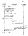
- FIG. 9 is a sequence diagram illustrating a flow of data transmission in which an RRC connection is not established. The process illustrated in FIG. 9 includes the following steps:
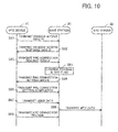
- FIG. 10 is a sequence diagram illustrating a flow of data transmission in which the RRC connection is established. The process illustrated in FIG. 10 includes the following steps:
- the second embodiment provides a radio communication system in which the MTC devices 10 does not perform a process for establishing an RRC connection and transmits MTC data to the base station 20. Accordingly, even in the case where the MTC data having a relatively small size is intermittently transmitted, the MTC device 10 deletes overhead of radio communication along with establishment and release of the RRC connection and efficiently transmits the MTC data.
- the base station 20 authenticates a terminal ID, an MTC device which is capable of transmitting data without establishing the RRC connection and an MTC device which is incapable of transmitting data without establishing the RRC connection are mixed.
- the Msg 3 is used as a message for inserting the MTC data.
- a message used to transmit the MTC data is not limited to the Msg 3, and also other messages may be used at timing at which the MTC device 10 is able to transmit an RRC control parameter to the base station 20.
Landscapes
- Engineering & Computer Science (AREA)
- Computer Networks & Wireless Communication (AREA)
- Signal Processing (AREA)
- Physics & Mathematics (AREA)
- General Physics & Mathematics (AREA)
- Mobile Radio Communication Systems (AREA)
- Communication Control (AREA)
Applications Claiming Priority (1)
| Application Number | Priority Date | Filing Date | Title |
|---|---|---|---|
| PCT/JP2010/060380 WO2011158377A1 (fr) | 2010-06-18 | 2010-06-18 | Procédé de communication sans fil, appareil de communication sans fil et système de communication sans fil |
Publications (2)
| Publication Number | Publication Date |
|---|---|
| EP2584801A1 true EP2584801A1 (fr) | 2013-04-24 |
| EP2584801A4 EP2584801A4 (fr) | 2013-08-14 |
Family
ID=45347797
Family Applications (1)
| Application Number | Title | Priority Date | Filing Date |
|---|---|---|---|
| EP10853257.3A Withdrawn EP2584801A4 (fr) | 2010-06-18 | 2010-06-18 | Procédé de communication sans fil, appareil de communication sans fil et système de communication sans fil |
Country Status (7)
| Country | Link |
|---|---|
| US (1) | US8995928B2 (fr) |
| EP (1) | EP2584801A4 (fr) |
| JP (1) | JP5545368B2 (fr) |
| KR (1) | KR101592630B1 (fr) |
| CN (1) | CN102934469B (fr) |
| CA (1) | CA2801357C (fr) |
| WO (1) | WO2011158377A1 (fr) |
Cited By (2)
| Publication number | Priority date | Publication date | Assignee | Title |
|---|---|---|---|---|
| EP2802177A4 (fr) * | 2012-01-06 | 2016-01-27 | Fujitsu Ltd | Station de base, terminal sans fil, système de communication sans fil, et procédé de communication sans fil |
| EP2868154A4 (fr) * | 2012-06-27 | 2016-02-10 | Lg Electronics Inc | Procédé et appareil pour effectuer une procédure d'accès aléatoire dans un système de communication sans fil |
Families Citing this family (7)
| Publication number | Priority date | Publication date | Assignee | Title |
|---|---|---|---|---|
| WO2013161798A1 (fr) * | 2012-04-27 | 2013-10-31 | 三菱電機株式会社 | Système de communication |
| US10306596B2 (en) | 2012-05-10 | 2019-05-28 | Samsung Electronics Co., Ltd | Method and system for connectionless transmission during uplink and downlink of data packets |
| CA2825166C (fr) | 2013-02-07 | 2014-12-02 | Dyno Nobel Inc. | Systemes de distribution d'explosifs et procedes connexes |
| EP2955881B1 (fr) * | 2013-02-28 | 2020-05-27 | Huawei Technologies Co., Ltd. | Procédé de transmission de données et procédé de réception de données, et dispositif associé |
| CN105684469A (zh) | 2013-10-31 | 2016-06-15 | 日本电气株式会社 | Mtc所用的设备、系统和方法 |
| JP2015220740A (ja) * | 2014-05-21 | 2015-12-07 | 富士通株式会社 | 通信システム、静止端末及び基地局 |
| CN106162923A (zh) * | 2015-04-10 | 2016-11-23 | 中兴通讯股份有限公司 | 随机接入信令的重新发送方法及装置 |
Family Cites Families (15)
| Publication number | Priority date | Publication date | Assignee | Title |
|---|---|---|---|---|
| FI91699C (fi) * | 1992-08-14 | 1994-07-25 | Nokia Telecommunications Oy | Menetelmä käyttäjädatan siirtämiseksi pakettimuodossa solukkoradiojärjestelmässä sekä liikkuva asema |
| CA2240022C (fr) * | 1995-12-08 | 2002-02-19 | Amsc Subsidiary Corporation | Communications mobiles a partir d'un systeme de repartition assistee par ordinateur par l'intermediaire d'une passerelle d'abonne pour systeme de communication par satellite |
| US6973034B1 (en) * | 1999-06-29 | 2005-12-06 | Cisco Technology, Inc. | Technique for collecting operating information from network elements, and for controlling network element behavior in a feedback-based, adaptive data network |
| US5946630A (en) * | 1996-07-10 | 1999-08-31 | Telefonaktiebolaget L M Ericsson (Publ) | Method for storing and forwarding short messages to mobile subscribers in a cellular communications system |
| US6014089A (en) | 1996-10-28 | 2000-01-11 | Tracy Corporation Ii | Method for transmitting data using a digital control channel of a wireless network |
| US6150955A (en) | 1996-10-28 | 2000-11-21 | Tracy Corporation Ii | Apparatus and method for transmitting data via a digital control channel of a digital wireless network |
| JP2000004475A (ja) * | 1998-06-15 | 2000-01-07 | Nec Corp | 移動通信システムおよび移動通信方法 |
| US7672685B2 (en) * | 2001-10-17 | 2010-03-02 | Sony Corporation | Transmitter and transmission control method, and receiver and reception control method |
| US7471666B2 (en) * | 2002-06-04 | 2008-12-30 | Winbond Electronics Corporation | Message-type data communication apparatus used in a DECT system |
| DE10332746B4 (de) * | 2003-07-17 | 2005-10-13 | Siemens Ag | Beschleunigter Aufbau einer Verbindung zwischen mehreren Mobilfunkteilnehmern |
| KR100742359B1 (ko) | 2005-03-22 | 2007-07-25 | 엘지전자 주식회사 | 단문 메시지 예약 전송 방법 및 장치 |
| KR100742362B1 (ko) | 2005-10-04 | 2007-07-25 | 엘지전자 주식회사 | 이동통신 네트워크에서 콘텐츠를 안전하게 송수신하기 위한 방법 및 장치 |
| JP2008148134A (ja) * | 2006-12-12 | 2008-06-26 | Toshiba Digital Media Engineering Corp | 移動通信システム、基地局装置および移動無線端末装置 |
| US20090086698A1 (en) * | 2007-09-27 | 2009-04-02 | Interdigital Patent Holdings, Inc. | Method and apparatus for managing a collision in common e-dch transmissions |
| WO2009061255A1 (fr) * | 2007-11-05 | 2009-05-14 | Telefonaktiebolaget L M Ericsson (Publ) | Détection de la collision de préambules d'accès direct |
-
2010
- 2010-06-18 WO PCT/JP2010/060380 patent/WO2011158377A1/fr not_active Ceased
- 2010-06-18 JP JP2012520233A patent/JP5545368B2/ja not_active Expired - Fee Related
- 2010-06-18 KR KR1020127032572A patent/KR101592630B1/ko not_active Expired - Fee Related
- 2010-06-18 EP EP10853257.3A patent/EP2584801A4/fr not_active Withdrawn
- 2010-06-18 CN CN201080067324.7A patent/CN102934469B/zh not_active Expired - Fee Related
- 2010-06-18 CA CA2801357A patent/CA2801357C/fr not_active Expired - Fee Related
-
2012
- 2012-12-03 US US13/692,408 patent/US8995928B2/en not_active Expired - Fee Related
Cited By (5)
| Publication number | Priority date | Publication date | Assignee | Title |
|---|---|---|---|---|
| EP2802177A4 (fr) * | 2012-01-06 | 2016-01-27 | Fujitsu Ltd | Station de base, terminal sans fil, système de communication sans fil, et procédé de communication sans fil |
| EP2868154A4 (fr) * | 2012-06-27 | 2016-02-10 | Lg Electronics Inc | Procédé et appareil pour effectuer une procédure d'accès aléatoire dans un système de communication sans fil |
| EP3297387A1 (fr) * | 2012-06-27 | 2018-03-21 | LG Electronics Inc. | Procédé et appareil permettant de réaliser une procédure d'accès aléatoire dans un système de communication sans fil |
| US10075979B2 (en) | 2012-06-27 | 2018-09-11 | Lg Electronics Inc. | Method and apparatus for performing random access procedure in wireless communication system |
| US10397959B2 (en) | 2012-06-27 | 2019-08-27 | Lg Electronics Inc. | Method and apparatus for performing random access procedure in wireless communication system |
Also Published As
| Publication number | Publication date |
|---|---|
| JPWO2011158377A1 (ja) | 2013-08-15 |
| WO2011158377A1 (fr) | 2011-12-22 |
| CN102934469A (zh) | 2013-02-13 |
| KR101592630B1 (ko) | 2016-02-05 |
| KR20130018417A (ko) | 2013-02-21 |
| CA2801357C (fr) | 2015-09-29 |
| CN102934469B (zh) | 2015-04-15 |
| JP5545368B2 (ja) | 2014-07-09 |
| US8995928B2 (en) | 2015-03-31 |
| EP2584801A4 (fr) | 2013-08-14 |
| CA2801357A1 (fr) | 2011-12-22 |
| US20130095767A1 (en) | 2013-04-18 |
Similar Documents
| Publication | Publication Date | Title |
|---|---|---|
| CA2801357C (fr) | Procede de communication sans fil, appareil de communication sans fil et systeme de communication sans fil | |
| US10841958B2 (en) | Access node, a method for an access node, a wireless terminal and a method for a wireless terminal | |
| CN103857037B (zh) | 移动无线设备和操作方法 | |
| KR20110081724A (ko) | 이동통신 시스템에서 고절전 수신모드 디바이스 통신을 위한 페이징 방법 및 장치와 그 시스템 | |
| CN107925946A (zh) | 在移动通信系统中当应用非连续接收模式时使用有效定时器管理存储的系统信息的方法和装置 | |
| CN102149166B (zh) | 无线接入网络的选择方法和系统 | |
| CN105323231B (zh) | 安全算法选择方法、装置及系统 | |
| WO2015115749A1 (fr) | Procédé de notification pour système communication d2d et dispositif associé | |
| CN102742337B (zh) | 数据的传输方法及装置、移动终端 | |
| CN108141815A (zh) | 无线网络中的系统信息广播 | |
| EP3593563B1 (fr) | Établissement de connexion d'un terminal sur un noeud de relais dans un système de communication sans fil | |
| JP2020536442A (ja) | コアネットワークノードのための方法、ueのための方法、コアネットワークノード、及びue | |
| EP3091795B1 (fr) | Procédé de gestion d'une réception discontinue dans un système de communication sans fil et système de communication sans fil associé | |
| EP3051851A1 (fr) | Terminal utilisateur et dispositif de réseau | |
| US11381343B2 (en) | Uplink data transmission confirmation apparatus, device, and method | |
| CN107006004A (zh) | 用于支持设备对设备通信的用户设备的下行链路传输调度 | |
| CN106792428A (zh) | 基站、近距离业务功能实体及通信资源分配、调度方法 | |
| CN105103599B (zh) | 一种设备识别码的收发方法和相关设备 | |
| KR20230022994A (ko) | 통신 방법, 사용자 기기, 기지국 기기 및 컴퓨터 저장매체(communication method, user equipment, base station device, and computer storage medium) | |
| CN103067953A (zh) | 一种小区状态上报、获取、监测、控制方法及设备 | |
| JP6455768B2 (ja) | アップリンクデータ伝送確認装置、デバイスおよび方法 | |
| US8903388B2 (en) | Compact base station device and signaling method | |
| CN103249161A (zh) | 资源调度的方法和装置 |
Legal Events
| Date | Code | Title | Description |
|---|---|---|---|
| PUAI | Public reference made under article 153(3) epc to a published international application that has entered the european phase |
Free format text: ORIGINAL CODE: 0009012 |
|
| 17P | Request for examination filed |
Effective date: 20130114 |
|
| AK | Designated contracting states |
Kind code of ref document: A1 Designated state(s): AL AT BE BG CH CY CZ DE DK EE ES FI FR GB GR HR HU IE IS IT LI LT LU LV MC MK MT NL NO PL PT RO SE SI SK SM TR |
|
| A4 | Supplementary search report drawn up and despatched |
Effective date: 20130715 |
|
| RIC1 | Information provided on ipc code assigned before grant |
Ipc: G08C 17/00 20060101AFI20130709BHEP Ipc: H04L 29/08 20060101ALI20130709BHEP Ipc: H04W 28/06 20090101ALI20130709BHEP Ipc: H04W 72/12 20090101ALI20130709BHEP Ipc: H04W 76/02 20090101ALI20130709BHEP Ipc: H04W 4/20 20090101ALI20130709BHEP Ipc: H04W 74/08 20090101ALI20130709BHEP |
|
| DAX | Request for extension of the european patent (deleted) | ||
| STAA | Information on the status of an ep patent application or granted ep patent |
Free format text: STATUS: EXAMINATION IS IN PROGRESS |
|
| 17Q | First examination report despatched |
Effective date: 20191203 |
|
| RIC1 | Information provided on ipc code assigned before grant |
Ipc: G08C 17/00 20060101ALI20200803BHEP Ipc: H04W 76/14 20180101ALI20200803BHEP Ipc: H04W 28/06 20090101AFI20200803BHEP Ipc: H04W 72/12 20090101ALN20200803BHEP |
|
| GRAP | Despatch of communication of intention to grant a patent |
Free format text: ORIGINAL CODE: EPIDOSNIGR1 |
|
| STAA | Information on the status of an ep patent application or granted ep patent |
Free format text: STATUS: GRANT OF PATENT IS INTENDED |
|
| RIC1 | Information provided on ipc code assigned before grant |
Ipc: H04W 28/06 20090101AFI20200910BHEP Ipc: H04W 76/14 20180101ALI20200910BHEP Ipc: G08C 17/00 20060101ALI20200910BHEP Ipc: H04W 72/12 20090101ALN20200910BHEP |
|
| INTG | Intention to grant announced |
Effective date: 20201005 |
|
| STAA | Information on the status of an ep patent application or granted ep patent |
Free format text: STATUS: THE APPLICATION IS DEEMED TO BE WITHDRAWN |
|
| 18D | Application deemed to be withdrawn |
Effective date: 20210216 |