EP2584829B1 - Dispositif relais et son procédé pour un système de communication sans fil - Google Patents
Dispositif relais et son procédé pour un système de communication sans fil Download PDFInfo
- Publication number
- EP2584829B1 EP2584829B1 EP11795596.3A EP11795596A EP2584829B1 EP 2584829 B1 EP2584829 B1 EP 2584829B1 EP 11795596 A EP11795596 A EP 11795596A EP 2584829 B1 EP2584829 B1 EP 2584829B1
- Authority
- EP
- European Patent Office
- Prior art keywords
- information
- wireless communication
- relay device
- communication devices
- processing unit
- Prior art date
- Legal status (The legal status is an assumption and is not a legal conclusion. Google has not performed a legal analysis and makes no representation as to the accuracy of the status listed.)
- Not-in-force
Links
Images





Classifications
-
- H—ELECTRICITY
- H04—ELECTRIC COMMUNICATION TECHNIQUE
- H04W—WIRELESS COMMUNICATION NETWORKS
- H04W16/00—Network planning, e.g. coverage or traffic planning tools; Network deployment, e.g. resource partitioning or cells structures
- H04W16/24—Cell structures
- H04W16/26—Cell enhancers or enhancement, e.g. for tunnels, building shadow
-
- H—ELECTRICITY
- H04—ELECTRIC COMMUNICATION TECHNIQUE
- H04B—TRANSMISSION
- H04B7/00—Radio transmission systems, i.e. using radiation field
- H04B7/14—Relay systems
- H04B7/15—Active relay systems
-
- H—ELECTRICITY
- H04—ELECTRIC COMMUNICATION TECHNIQUE
- H04B—TRANSMISSION
- H04B7/00—Radio transmission systems, i.e. using radiation field
- H04B7/14—Relay systems
- H04B7/15—Active relay systems
- H04B7/155—Ground-based stations
-
- H—ELECTRICITY
- H04—ELECTRIC COMMUNICATION TECHNIQUE
- H04L—TRANSMISSION OF DIGITAL INFORMATION, e.g. TELEGRAPHIC COMMUNICATION
- H04L49/00—Packet switching elements
- H04L49/90—Buffering arrangements
- H04L49/9057—Arrangements for supporting packet reassembly or resequencing
-
- H—ELECTRICITY
- H04—ELECTRIC COMMUNICATION TECHNIQUE
- H04W—WIRELESS COMMUNICATION NETWORKS
- H04W28/00—Network traffic management; Network resource management
- H04W28/02—Traffic management, e.g. flow control or congestion control
- H04W28/0215—Traffic management, e.g. flow control or congestion control based on user or device properties, e.g. MTC-capable devices
-
- H—ELECTRICITY
- H04—ELECTRIC COMMUNICATION TECHNIQUE
- H04W—WIRELESS COMMUNICATION NETWORKS
- H04W28/00—Network traffic management; Network resource management
- H04W28/02—Traffic management, e.g. flow control or congestion control
- H04W28/10—Flow control between communication endpoints
-
- H—ELECTRICITY
- H04—ELECTRIC COMMUNICATION TECHNIQUE
- H04W—WIRELESS COMMUNICATION NETWORKS
- H04W4/00—Services specially adapted for wireless communication networks; Facilities therefor
- H04W4/30—Services specially adapted for particular environments, situations or purposes
- H04W4/38—Services specially adapted for particular environments, situations or purposes for collecting sensor information
-
- H—ELECTRICITY
- H04—ELECTRIC COMMUNICATION TECHNIQUE
- H04W—WIRELESS COMMUNICATION NETWORKS
- H04W84/00—Network topologies
- H04W84/02—Hierarchically pre-organised networks, e.g. paging networks, cellular networks, WLAN [Wireless Local Area Network] or WLL [Wireless Local Loop]
- H04W84/04—Large scale networks; Deep hierarchical networks
- H04W84/042—Public Land Mobile systems, e.g. cellular systems
- H04W84/047—Public Land Mobile systems, e.g. cellular systems using dedicated repeater stations
Definitions
- the present disclosure relates to a relay device, a relay method, a wireless communication system, a base station, and a wireless communication device.
- the 4G makes it possible to use techniques such as a relay or carrier aggregation, thereby improving the maximum communication speed and the quality at cell edges.
- Relay devices relay nodes
- Relay nodes that performs a relay are described, for example, in the Patent Literature below.
- MTC Machine Type Communications
- a next-generation power transmission network called a Smart Grid
- the Smart Grid When the Smart Grid is applied to the electric power meter which measures an electric power consumption of each home, it is considered that electric power consumptions of geographically remote locations can be aggregated and managed. Further, when the Smart Grid is applied to the individual power-consuming appliance in addition to the electric power meter, more flexible power management is possible.
- MTC applications a variety of applications such as an application for collecting information relevant to health care instruments, an application for collecting sales information in a vending machine or the like have been considered.
- the MTC terminal is a terminal designed specifically for these applications.
- a relay device in which all features of the precharacterizing part of claim 1 are disclosed, is described in US 2009/085769 A1 .
- a communication system including a base station, mobile station and relay station configured to relay the communication between the base station and the mobile station, in which resource blocks of base station uplinks are divided on the basis of a plurality of frequency channels in the frequency direction and a plurality of time slots in the time direction.
- a wireless communication device such as MTC terminal and a relay device.
- a plurality of structural elements having substantially the same functional configuration may be distinguished from each other by each having a different alphabetical letter added to the end of the same reference numeral.
- a plurality of structural elements having substantially the same functional configuration may be distinguished from each other as necessary, such as MTC terminals 20A, 20B, and 20C.
- MTC terminals 20A, 20B, and 20C are simply referred to as the MTC terminal 20.
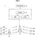
- Fig. 1 is an explanatory diagram illustrating an exemplary configuration of a wireless communication system 1.
- the wireless communication system 1 includes an eNodeB 10, a core network, MTC terminals 20, a MTC server 30, and a relay device 40.
- the core network includes a MME (Mobility Management Entity) 12, an S-GW (Serving Gateway) 14, and a PDN (Packet Data Network)-GW 16.
- MME Mobility Management Entity
- S-GW Serving Gateway
- PDN Packet Data Network
- the MTC terminal 20 is an example of a wireless communication device.
- the wireless communication device may be a mobile phone and the like that is a non-MTC terminal among user equipment (UE: User Equipment).
- UE User Equipment
- the eNodeB 10 is a radio base station that acts as a transmitter for transmitting wireless signals to the MTC terminal 20 and as a receiver for receiving wireless signals from the MTC terminal 20. Note that only one eNodeB 10 is shown in Fig. 1 , but in practice a plurality of eNodeBs can be connected to the core network. In addition, although the illustration is omitted from Fig. 1 , the eNodeB 10 is also communicated, with the user equipment other than the MTC terminal 20, for example.
- the MME 12 is a device that controls the setup, opening and handover of sessions for data communication.
- the MME 12 is connected to the eNodeB 10 through an interface called X2.
- the S-GW 14 is a device that performs the routing, transfer, and so on, of user data.
- the PDN-GW 16 acts as a connection point to IP service network and transfers user data from and to the IP service network.
- the MTC terminal 20 is a terminal designed specifically for applications for MTC which has been studied in 3GPP and performs a wireless communication with the eNodeB 10 depending on the applications. In addition, the MTC terminal 20 performs a bidirectional communication with the MTC server 30 through the core network. An example of the applications for the MTC is described below.
- the MTC terminal 20 may be an electrocardiogram measuring device corresponding to "4. Health" in the list above.
- the MTC server 30 requests the MTC terminal 20 to report the electrocardiogram measurements, and then the electrocardiogram measurements are reported from the MTC terminal 20 to the MTC server 30.
- the MTC terminal 20 may be a vending machine corresponding to "3. Payment" in the list above.
- the MTC server 30 requests the MTC terminal 20 to report the sales volume, and then the sales volume is reported from the MTC terminal 20 to the MTC server 30.
- MTC terminal 20 The characteristics of such MTC terminal 20 are described below. In addition, the MTC terminal 20 is not necessary to have all of the characteristics described below.
- the MTC terminal 20 has a little movement, has a few connections to the eNodeB 10 to communicate a small amount of data, and then again returns to idle mode. Further, some amount of delay is acceptable in data communication.
- the relay device 40 relays communication between the eNodeB 10 and the MTC terminal 20.
- MTC terminals 20D to 20F are spaced apart from the eNodeB 10 as shown in Fig. 1 , they can communicate with the eNodeB 10 through the relay device 40.
- links between the eNodeB 10 and the relay device 40 may be referred to as backhaul link (Backhaul Link), and links between the relay device 40 and MTC terminals 20 may be referred to as access link.
- a flow of relay communication performed by a relay device 70 according to a comparative example will be described below in order to clarify the general principles of embodiments of the present disclosure.
- Fig. 2 is an explanatory diagram illustrating a flow of relay communication performed between the eNodeB 10 and the non-MTC terminal 24 by the relay device 70 according to the comparative example.
- the relay device 70 according to the comparative example when receiving an uplink grant which contains scheduling information for the non-MTC terminal 24 belonging to the relay device 70 from the eNodeB 10 (S104), relays the uplink grant to the non-MTC terminal 24 (S108).
- the relay device 70 when receiving uplink data from the non-MTC terminal 24 (S112), relays the uplink data to the eNodeB 10 (S116). Similarly, when the eNodeB 10 transmits downlink data which will be transmitted to the non-MTC terminal 24 (S120), the relay device 70 relays the downlink data to the non-MTC terminal 24 (S124).
- MTC terminals 20 it is considered that a variety of equipment will be operated as MTC terminals 20 in the future. Thus, it is expected that a large number of MTC terminals 20 would be accommodated in each cell. Further, when these MTC terminals 20 communicate with the eNodeB 10 through the relay device 70 according to the comparative example, the number of exchange of information would be doubled. These circumstances will be described below with reference to Fig. 3 .
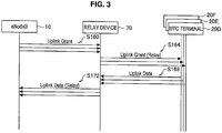
- Fig. 3 is an explanatory diagram illustrating a flow of relay communication performed between the eNodeB 10 and the MTC terminal 20 by the relay device 70 according to the comparative example.
- the eNodeB 10 transmits individual uplink grants to the corresponding MTC terminals 20 (S160).
- the relay device 70 when receiving the uplink grants from the eNodeB 10, individually transmits the uplink grants to the corresponding MTC terminals 20 (S164).
- the relay device 70 when receiving the uplink grants from the respective MTC terminals 20 (S168), transmits individual uplink data transmitted from each of the respective MTC terminals 20 to the eNodeB 10 (S 172).
- the uplink grant includes a CRC field (UE Identity), a resource grant field, a MCS field (Modulation and Coding Scheme), a power control field, and so on.
- CRC field UE Identity
- resource grant field UE Identity
- MCS field Modulation and Coding Scheme
- the CRC field is scrambled with a unique code of a MTC terminal 20 which will be a destination. Thus, it is possible to specify a MTC terminal 20 which will be a destination, on the basis of the code used for scrambling the CRC field.
- the resource grant field contains information indicating a resource which acknowledges the transmission of uplink data from a MTC terminal 20.
- the MCS field or the power control field contains information that indicates a rate upon transmitting uplink data or a transmission power.
- the individual uplink grants are transmitted from the eNodeB 10 to the corresponding MTC terminals 20 through the relay device 70.
- the traffic for transmitting the uplink grant between the eNodeB 10 and the relay device 70 is increased in proportion to the increase of the number of MTC terminals 20 which will be destinations. The similar problem is occurred even when the data communication is performed.
- the relay device 40 is incorporated with a novel function for suppressing the increase of network load due to the increase of the number of MTC terminals 20.
- the relay device 40 according to the embodiment of the present disclosure will be described in detail below.
- Fig. 5 is a functional block diagram illustrating the configuration of the relay device 40 according to the first embodiment.
- the relay device 40 includes an antenna 410, a reception processing unit 420, a storage unit 430, an information processing unit 440, and a transmission processing unit 450.
- the antenna 410 receives a wireless signal from an eNodeB 10, a MTC terminal 20, a non-MTC terminal 24, or the like, and converts the wireless signal into an electric reception signal.
- the reception signal obtained by the antenna 410 is supplied to the reception processing unit 420.
- the antenna 410 converts a transmission signal supplied from the transmission processing unit 450 into a wireless signal, and transmits the wireless signal to the eNodeB 10, the MTC terminal 20, the non-MTC terminal 24, or the like.
- the relay device 40 may include a plurality of antennas.
- the relay device 40 when including a plurality of antennas, can perform MIMO (Multiple Input Multiple Output) communication, diversity communication, or the like.
- MIMO Multiple Input Multiple Output
- the antenna 410 functions as a receiving unit and a transmitting unit.
- the reception processing unit 420 performs a demodulation process, a decoding process or the like on the reception signal supplied from the antenna 410.
- the relay device 40 may simply amplify the electric power of the reception signal, without performing the demodulation or decoding process in the reception processing unit 420 at the time of relaying.
- the storage unit 430 accumulates information transmitted on the uplink among information obtained by the reception processing unit 420.
- the information processing unit 440 when receiving information aggregated for the plurality of MTC terminals 20 from the eNodeB 10, obtains individual information for each of the plurality of MTC terminals 20 based on the aggregated information.
- Examples of the aggregated information include a group uplink grant, a group ACK, and so on.
- Information with regard to an uplink grant for the plurality of MTC terminals 20 is aggregated in the group uplink grant.
- Information with regard to an ACK for the plurality of MTC terminals 20 is aggregated in the group ACK.
- examples of the individual information include an uplink grant relative to each of the MTC terminals 20, an ACK relative to each of the MTC terminals 20, and so on.
- the information processing unit 440 aggregates information from the plurality of MTC terminals 20 accumulated in the storage unit 430 into a single data frame with respect to the uplink. For example, when new uplink data transmitted from the plurality of MTC terminals 20 is accumulated, the information processing unit 440 aggregates these uplink data to generate group uplink data.
- the information processing unit 440 may aggregate information accumulated in the storage unit 430 to relay data received from the MTC terminals 20 within a predetermined period of time to the eNodeB 10.
- the predetermined period of time may be ten seconds, one minute, thirty minutes, one hour, or the like.
- information related to an allowable delay time may be contained in a data frame of the uplink from the MTC terminal 20.
- the allowable delay time may be different for each of the MTC terminals 20. Therefore, the relay device 40, before the shortest time among the allowable delay time of an uplink data received from each of the MTC terminals 20 elapses, may aggregate information accumulated in the storage unit 430 until then and relay it to the eNodeB 10.
- the information processing unit 440 may aggregate information accumulated in the storage unit 430 when the number of pieces of information accumulated in the storage unit 430 reaches a predetermined number. As an alternative, the information processing unit 440 may aggregate information accumulated in the storage unit 430 when the total sum of the amount of information accumulated in the storage unit 430 reaches an upper limit value.
- the transmission processing unit 450 generates a transmission signal based on information obtained by the information processing unit 440 and supplies the transmission signal to the antenna 410,. For example, the transmission processing unit 450 generates transmission signals of individual information (uplink grant, ACK, and so on) relative to each of the MTC terminals 20 obtained by the information processing unit 440 with respect to the downlink. The individual information generated by the transmission processing unit 450 is individually transmitted from the antenna 410 to the corresponding MTC terminals 20.
- the transmission processing unit 450 generates a transmission signal based on information aggregated by the information processing unit 440 with respect to the uplink.
- the transmission signal of the aggregated information generated by the transmission processing unit 450 is transmitted from the antenna 410 to the eNodeB 10.
- the configuration of the relay device 40 according to the first embodiment of the present disclosure has been described above. Subsequently, an operation of a wireless communication system 1 which includes the relay device 40 according to the first embodiment of the present disclosure will be described.
- Fig. 6 is a sequence diagram illustrating a first operation example of a downlink.
- the eNodeB 10 transmits a group uplink grant to the relay device 40 (S204).
- S204 the relay device 40
- a configuration of the group uplink grant in the operation example will be described with reference to Fig. 7 .
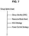
- Fig. 7 is an explanatory diagram illustrating the configuration of the group uplink grant in the first operation example.
- the group uplink grant in the operation example includes a CRC field (Group Identity), a resource block field, a MCS strategy field (Modulation and Coding Scheme Strategy), a power control strategy field, and so on.
- the CRC field is a field for identifying a group consisting of a plurality of MTC terminals 20, and is scrambled with a unique code of each group.
- the plurality of MTC terminals 20 are grouped by the relay device 40 according to a predetermined criterion.
- the MTC terminals 20 may be grouped and the grouped information may be stored to the relay device 40 by a user, at the time such as when a MTC terminal 20, a relay device 40 or the like is provide. For this reason, the relay device 40 is aware of a unique code as identifier information of each group and identification information of a MTC terminal 20 belonging to each group.
- identifier information of each group has been transmitted in advance to the eNodeB 10 by the relay device 40, thus the eNodeB 10 can hold identifier information of each group received from the relay device 40 and scramble the CRC field with the unique code of the group based on the information.
- the relay device 40 may or may not share with the eNodeB 10 the identification information of MTC terminals 20 belonging to each group.
- the relay device 40 may form a single group for all of the MTC terminals 20 belonging to the relay device 40.
- the resource block field contains information indicating a resource which acknowledges the transmission of an uplink data from a plurality of MTC terminals 20 within a group identified by the CRC field.
- the MCS strategy field or power control strategy field contains information that indicates a strategy of a rate or transmission power.
- the MCS strategy field may contain information that indicates a maximum value of a rate
- the power control strategy field may contain information that indicates a maximum value of a transmission power.
- information that indicates a strategy of a rate or transmission power may be contained in each resource.
- the relay device 40 generates an uplink grant relative to each of the MTC terminals 20 based on a group uplink grant as described above. Specifically, when the information processing unit 440 of the relay device 40 is aware of a unique code as identifier information of each group and identification information of MTC terminal 20 belonging to each group as described above, a MTC terminal 20 which will be a destination is specified on the basis of a code for scrambling the CRC field. Then, the information processing unit 440 of the relay device 40 performs resource allocation to each of the MTC terminals specified by the CRC field within the range of resource indicated by the resource block field (S208).
- the information processing unit 440 determines a MTC or power of each of the MTC terminals 20 specified by the CRC field according to a MCS strategy field or power control strategy field. Then, an uplink grant relative to each of the corresponding MTC terminals 20 generated by the information processing unit 440 is individually transmitted from the antenna 410 by the relay device 40 (S212).
- the relay device 40 receives a group uplink grant from the eNodeB 10.
- Uplink grants relative to a plurality of MTC terminals 20 are aggregated in the group uplink grant.
- this group uplink grant specifies a resource which acknowledges the allocation by the relay device 40, instead of individually specifying a resource to be allocated to each of the MTC terminals 20, thus the amount of information related to resource information is significantly suppressed.
- the amount of traffic between the eNodeB 10 and the relay device 40 can be suppressed, thereby reducing network load.
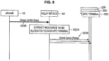
- Fig. 8 is a sequence diagram illustrating a second operation example of the downlink. As shown in Fig. 8 , the eNodeB 10 first transmits a group uplink grant to the relay device. In this regard, the configuration of the group uplink grant in the operation example will be described with reference to Fig. 9 .
- Fig. 9 is an explanatory diagram illustrating the configuration of the group uplink grant in the second operation example.
- the group uplink grant in the operation example includes a user equipment identity list (UE Identity List), a resource grant list (Resource Grant List), a MCS strategy field, a power control strategy field, and so on.
- UE Identity List user equipment identity list
- Resource Grant List resource grant list
- MCS strategy field MCS strategy field
- power control strategy field a power control strategy field
- the user equipment identity list is comprised of information for identifying each of the MTC terminals 20.
- the resource grant list contains information indicating a resource in which the transmission of uplink data from each of the MTC terminals 20 identified in the user equipment identity list is acknowledged.
- the MCS strategy field or power control strategy field contains information that indicates a strategy of a rate or transmission power, as similar to the first operation example.
- the relay device 40 generates an uplink grant relative to each of the MTC terminals 20, based on the group uplink grant as described above. Specifically, the information processing unit 440 of the relay device 40 generates the uplink grant by dividing information included in the group uplink grant, that is, by extracting a resource to be allocated to each of the MTC terminals 20 (S224). Similarly, the information processing unit 440 determines a MTC or power of each of the MTC terminal 20 identified in the user equipment identity list according to a MCS strategy field or power control strategy field.
- the uplink grants relative to each of the MTC terminals 20 generated by the information processing unit 440 is individually transmitted from the antenna 410 by the relay device 40 (S228).
- the relay device 40 receives a group uplink grant in which uplink grants relative to a plurality of MTC terminals 20 are aggregated from the eNodeB 10.
- the group uplink grant is not intended to specify a resource which acknowledges the allocation by the relay device 40.
- control fields such as a format ID field indicating frame content or a CRC field can be unified, thereby anticipating the effect on the traffic suppression.
- Fig. 10 is an explanatory diagram illustrating a flow of relay communication performed between the eNodeB 10 and MTC terminal 20 by the relay device 70 according to a comparative example.
- each MTC terminal 20 individually transmits uplink data using different resources (S180).
- the relay device 70 when receiving uplink data from each of the MTC terminals 20, individually transmits the received uplink data to the eNodeB 10 (S184). Then, the relay device 70, when receiving ACKs transmitted individually to each of the MTC terminals 20 from the eNodeB 10 (S188), transmits the ACK to each of the MTC terminals 20 (S 192).
- the relay device 70 individually transmits the uplink data received from each of the MTC terminal 20 to the eNodeB 10, and individually receives ACKs relative to each of the MTC terminals 20 from the eNodeB 10.
- the relay device 40 according to the embodiment of the present disclosure, as will be described below with reference to Fig. 11 , can communicate the grouped uplink data or ACK between the eNodeB 10 and the relay device 40.
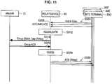
- Fig. 11 is a sequence diagram illustrating an operation example of an uplink. As shown in Fig. 11 , each MTC terminal 20 individually transmits uplink data using different resources (S304). The relay device 40, when receiving uplink data from each of the MTC terminals 20, accumulates the received uplink data to the storage unit 430 (S308).
- the information processing unit 440 of the relay device 40 aggregates the uplink data accumulated in the storage unit 430 to generate group uplink data (S312).
- the relay device 40 then, as shown in Fig. 11 , transmits the group uplink data to the eNodeB 10 (S316).
- the eNodeB 10 transmits a group ACK in which ACK information for a plurality of the MTC terminals 20 is aggregated (S320). Then, the information processing unit 440 of the relay device 40 divides the group ACK to obtains ACKs for each of the MTC terminals 20 (S324). The relay device 40 then transmits the ACKs to the corresponding MTC terminals 20 (S328).
- the relay device 40 rapidly relays the uplink data from the non-MTC terminal 24 while accumulating and aggregating the uplink data from the MTC terminal 20.
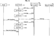
- Fig. 12 is a sequence diagram illustrating an operation according to the second embodiment of the present disclosure.
- the relay device 40 when receiving uplink data from a MTC terminal 20F (S332), accumulates the uplink data to the storage unit 430 (S336).
- the relay device 40 when receiving uplink data from a MTC terminal 20E (S340), accumulates the uplink data to the storage unit 430 (S344).
- the relay device 40 when receiving uplink data from a non-MTC terminal 24 (S348), transmits the uplink data to the eNodeB 10 without aggregating the uplink data (S352).
- the relay device 40 when receiving uplink data from the MTC terminal 20E (S356), accumulates the uplink data to the storage unit 430 (S360). Then, the information processing unit 440 of the relay device 40 aggregates the uplink data accumulated in the storage unit 430 to generate group uplink data (S364). And then, the relay device 40 transmits the group uplink data to the eNodeB 10 (S368).
- the relay device 40 when the relay device 40 receives uplink data, it determines whether this uplink data is transmitted from the MTC terminal 20 or from the non-MTC terminal 24. For example, when the uplink data contains information that indicates whether or not the uplink data is transmitted from the MTC terminal 20, or contains information that indicates whether or not the uplink data is transmitted from the non-MTC terminal 24, the relay device 40 may determine a terminal which will be a source on the basis of this information.
- the relay device 40 may determine a terminal which will be a source on the basis of the amount of uplink data. More specifically at this point, data transmitted from the MTC terminal 20 is assumed to be data that indicates the water or electricity consumption or the like. Also, the amount of data transmitted from the MTC terminal 20 is expected to be smaller compared to that of data transmitted from the non-MTC terminal 24. Thus, the relay device 40 may determine that the MTC terminal 20 is a source terminal when the amount of uplink data is less than a predetermined value, and may determine that the non-MTC terminal 24 is a source terminal when the amount of uplink data is greater than or equal to the predetermined value.
- the relay device 40 can appropriately change the details of relay process depending on whether a source terminal of the uplink data is a MTC terminal 20.
- the traffic can be suppressed by grouping information communicated between the eNodeB 10 and the relay device 40.
- the relay device 40 according to the second embodiment of the present disclosure can appropriately change the details of relay process depending on whether or not a source terminal of uplink data is a MTC terminal 20.
- each step in the process of the relay device 40 of the present specification do not necessarily have to be processed in a time series according to the order described as the sequence diagrams or flowcharts.
- each step in the process of the relay device 40 may be processed in an order different from the order described as sequence diagrams, or may be processed in parallel.
- a computer program for causing hardware such as CPU, ROM and RAM, embedded in the relay device 40 to realize an equivalent function as each element of the above-mentioned relay device 40 can also be created.
- a storage medium having the computer program stored thereon is also provided.
Landscapes
- Engineering & Computer Science (AREA)
- Computer Networks & Wireless Communication (AREA)
- Signal Processing (AREA)
- Mobile Radio Communication Systems (AREA)
- Radio Relay Systems (AREA)
Claims (8)
- Dispositif de relais (40) comprenant :une unité de réception (420) pour recevoir des informations dans des trames de données à partir d'une pluralité de dispositifs de communication sans fil (20) ;une unité de stockage (430) pour accumuler les informations reçues à partir de la pluralité de dispositifs de communication sans fil (20) par l'unité de réception (420) ;une unité de traitement d'informations (440) pour agréger les informations accumulées dans l'unité de stockage (430) ; etune unité de transmission (450) pour transmettre les informations agrégées par l'unité de traitement d'informations (440) à une station de base (10), dans lequelle dispositif de relais (40) est conçu pour déterminer si l'un de la pluralité des dispositifs de communication sans fil (20) à partir desquels les informations sont reçues est ou non un terminal MTC, dans lequell'unité de stockage (430) est conçue pour accumuler les informations reçues à partir du terminal MTC, etl'unité de traitement d'informations (440) est conçue pour agréger les informations reçues à partir du terminal MTC, etl'unité de transmission (450) est conçue pour transmettre les informations reçues à partir du dispositif de communication sans fil (20), qui est le terminal MTC, à la station de base (10) dans un état agrégé par l'unité de traitement d'informations (440),l'unité de traitement d'informations (440) est conçue pour déterminer à partir de chaque trame de données reçue à partir dudit terminal MTC des informations relatives à un temps de retard admissible, et dans lequel l'unité de traitement d'informations est en outre conçue pour déterminer à quel moment chacun des temps de retard admissibles des informations accumulées dans l'unité de stockage est écoulé et pour agréger les informations accumulées dans l'unité de stockage avant qu'un temps le plus précoce parmi les temps de retards admissibles ne soit écoulé.
- Dispositif de relais selon la revendication 1, dans lequel l'unité de stockage (430) est conçue pour accumuler des informations ayant une quantité inférieure ou égale à une quantité prédéterminée parmi les informations reçues à partir de la pluralité de dispositifs de communication sans fil (20), et dans lequel
l'unité de transmission (450) est conçue pour transmettre des informations ayant une quantité dépassant une quantité prédéterminée parmi les informations reçues à partir de la pluralité de dispositifs de communication sans fil (20), à la station de base (10) dans un état non agrégé avec d'autres informations. - Dispositif de relais selon la revendication 1 ou 2, dans lequel
l'unité de traitement d'informations (440) est conçue pour agréger les informations accumulées dans l'unité de stockage (430) à un cycle prédéterminé. - Dispositif de relais selon l'une quelconque des revendications 1 à 3, dans lequel
l'unité de réception (420) est conçue pour recevoir des informations agrégées pour une pluralité de dispositifs de communication sans fil (20) à partir d'une station de base (10) ;
l'unité de traitement d'informations (440) est conçue pour obtenir des informations individuelles pour chacun de la pluralité de dispositifs de communication sans fil (20) sur la base des informations agrégées reçues par l'unité de réception ; et
l'unité de transmission (450) est conçue pour transmettre individuellement les informations individuelles obtenues par l'unité de traitement d'informations à chacun de la pluralité de dispositifs de communication sans fil. - Dispositif de relais selon la revendication 4, dans lequel
les informations agrégées pour la pluralité de dispositifs de communication sans fil sont des informations de ressources, et dans lequel
l'unité de traitement d'informations (440) est conçue pour obtenir les informations individuelles en effectuant une allocation de ressources à chacun de la pluralité de dispositifs de communication sans fil (20) dans une plage d'une ressource indiquée par les informations de ressources. - Dispositif de relais selon la revendication 4, dans lequel
les informations agrégées pour la pluralité de dispositifs de communication sans fil comprennent des informations de ressources pour chacun de la pluralité de dispositifs de communication sans fil (20), et dans lequel
l'unité de traitement d'informations (440) est conçue pour obtenir les informations de ressources pour chacun de la pluralité de dispositifs de communication sans fil (20) en tant qu'informations individuelles. - Procédé de relais comprenant les étapes consistant à :recevoir (420) des informations contenues dans des trames de données à partir d'une pluralité de dispositifs de communication sans fil (20) ;accumuler (430) les informations reçues à partir de la pluralité de dispositifs de communication sans fil (20) ;agréger (440) les informations accumulées ; ettransmettre (450) les informations agrégées à une station de base (10),déterminer si l'un de la pluralité des dispositifs de communication sans fil (20) à partir desquels les informations sont reçues est ou non un terminal MTC,accumuler les informations reçues du dispositif de communication sans fil (20) qui est un terminal MTC, et déterminer à partir de chaque trame de données reçue à partir dudit terminal MTC des informations relatives à un temps de retard admissible des informations contenues dans la trame de données, et déterminer en outre à quel moment chacun des temps de retard admissibles des informations accumulées est écoulé et agréger les informations accumulées avant qu'un temps le plus précoce parmi les temps de retards admissibles ne soit écoulé,
etdans l'étape de transmission (450), les informations reçues à partir du dispositif de communication sans fil (20), qui est le terminal MTC à la station de base (10), dans un état agrégé sont transmises à la station de base (10). - Procédé de relais selon la revendication 7, comprenant en outre les étapes consistant à :recevoir (420) des informations agrégées pour une pluralité de dispositifs de communication sans fil (20) à partir d'une station de base (10) ;obtenir (440) des informations individuelles pour chacun de la pluralité de dispositifs de communication sans fil (20) sur la base des informations agrégées ; ettransmettre individuellement (450) les informations individuelles à chacun de la pluralité de dispositifs de communication sans fil (209).
Applications Claiming Priority (2)
| Application Number | Priority Date | Filing Date | Title |
|---|---|---|---|
| JP2010139935A JP2012004987A (ja) | 2010-06-18 | 2010-06-18 | 中継装置、中継方法、無線通信システム、基地局、および無線通信装置 |
| PCT/JP2011/062990 WO2011158688A1 (fr) | 2010-06-18 | 2011-06-07 | Dispositif relais, son procédé, système de communication sans fil, station de base et dispositif de communication sans fil |
Publications (3)
| Publication Number | Publication Date |
|---|---|
| EP2584829A1 EP2584829A1 (fr) | 2013-04-24 |
| EP2584829A4 EP2584829A4 (fr) | 2014-01-29 |
| EP2584829B1 true EP2584829B1 (fr) | 2018-03-14 |
Family
ID=45348094
Family Applications (1)
| Application Number | Title | Priority Date | Filing Date |
|---|---|---|---|
| EP11795596.3A Not-in-force EP2584829B1 (fr) | 2010-06-18 | 2011-06-07 | Dispositif relais et son procédé pour un système de communication sans fil |
Country Status (8)
| Country | Link |
|---|---|
| US (1) | US9755725B2 (fr) |
| EP (1) | EP2584829B1 (fr) |
| JP (1) | JP2012004987A (fr) |
| KR (1) | KR101829484B1 (fr) |
| CN (1) | CN102948204A (fr) |
| BR (1) | BR112012031622A2 (fr) |
| RU (1) | RU2566358C2 (fr) |
| WO (1) | WO2011158688A1 (fr) |
Families Citing this family (23)
| Publication number | Priority date | Publication date | Assignee | Title |
|---|---|---|---|---|
| WO2012043523A1 (fr) * | 2010-10-01 | 2012-04-05 | 三菱電機株式会社 | Système de communications |
| TW201419781A (zh) * | 2012-08-01 | 2014-05-16 | Interdigital Patent Holdings | 上鏈傳輸控制 |
| US9252866B2 (en) * | 2012-08-02 | 2016-02-02 | Sony Corporation | Relay node aggregation of data transfers in a wireless telecommunication system |
| EP2736205A1 (fr) * | 2012-11-22 | 2014-05-28 | Alcatel Lucent | Appareil et procédé permettant de réacheminer des paquets ou des messages |
| JP6142195B2 (ja) * | 2013-02-28 | 2017-06-07 | 株式会社国際電気通信基礎技術研究所 | 無線通信システム、無線基地局、無線通信方法、及びプログラム |
| FR3016104B1 (fr) * | 2013-12-30 | 2016-01-22 | Cassidian Sas | Procede de communication mis en œuvre par un nœud de relais |
| JP2015139178A (ja) * | 2014-01-24 | 2015-07-30 | 富士通株式会社 | 無線通信システム、無線通信方法、中継局、及び、無線基地局 |
| JP6304654B2 (ja) * | 2014-04-18 | 2018-04-04 | 国立研究開発法人情報通信研究機構 | リソース管理システム |
| CN105337893B (zh) * | 2014-05-30 | 2020-12-01 | 索尼公司 | 电子设备、中心节点和网络侧设备、传输方法和配置方法 |
| JP6268047B2 (ja) * | 2014-06-16 | 2018-01-24 | 株式会社日立製作所 | 基地局 |
| EP3167557B1 (fr) * | 2014-07-10 | 2020-01-01 | Sony Corporation | Appareil et procédés de télécommunications |
| US10470018B2 (en) * | 2014-10-24 | 2019-11-05 | Qualcomm Incorporated | Data aggregation and delivery |
| CN106658739B (zh) * | 2015-07-13 | 2020-01-31 | 中国移动通信集团公司 | 一种多ue上行子帧聚合传输方法、装置和系统 |
| JP6403280B2 (ja) * | 2015-07-21 | 2018-10-10 | 日本電信電話株式会社 | 無線通信システム、中継局装置及び無線通信方法 |
| WO2017051667A1 (fr) * | 2015-09-24 | 2017-03-30 | 日本電気株式会社 | Système de traitement de communication, procédé de traitement de message de groupe, dispositif de traitement de communication, procédé et programme de commande associés |
| JP6035445B2 (ja) * | 2016-04-25 | 2016-11-30 | 株式会社ラック | 情報処理システム、情報処理方法およびプログラム |
| CN107919949A (zh) * | 2016-10-10 | 2018-04-17 | 中兴通讯股份有限公司 | 一种中继通信方法和装置 |
| WO2018164885A1 (fr) * | 2017-03-10 | 2018-09-13 | Kyocera Corporation | Transmissions de communication de type machine (mtc) à rach en masse |
| JP2019009595A (ja) * | 2017-06-23 | 2019-01-17 | 日本電気株式会社 | 集約装置、集約方法およびプログラム |
| CN110875890B (zh) * | 2018-09-04 | 2022-02-18 | 华为技术有限公司 | 一种信息传输方法、装置及系统 |
| CN109981227A (zh) * | 2019-03-24 | 2019-07-05 | 北京工业大学 | 物联网场景中基于组通信的harq传输方法及控制系统 |
| WO2022128100A1 (fr) | 2020-12-17 | 2022-06-23 | Nokia Technologies Oy | Réception efficace des mesures de capteurs |
| WO2022155865A1 (fr) * | 2021-01-22 | 2022-07-28 | Qualcomm Incorporated | Transmission d'informations de commande dans une communication basée sur un relais, pour un équipement utilisateur à capacité réduite |
Family Cites Families (16)
| Publication number | Priority date | Publication date | Assignee | Title |
|---|---|---|---|---|
| JP4140572B2 (ja) | 2004-07-22 | 2008-08-27 | 三菱自動車工業株式会社 | 車両の荷室構造 |
| RU2007111456A (ru) | 2004-09-29 | 2008-10-10 | Мацусита Электрик Индастриал Ко., Лтд. (Jp) | Устройство радиосвязи и способ радиосвязи |
| JP4611842B2 (ja) | 2005-08-24 | 2011-01-12 | シャープ株式会社 | リピータ装置 |
| EP1804430B1 (fr) * | 2006-01-03 | 2013-05-15 | Samsung Electronics Co., Ltd. | Requête et allocation de la bande passante de flux montant dans un système de communication sans fil à relais et bonds multiples utilisant une large bande |
| US20080002741A1 (en) * | 2006-06-30 | 2008-01-03 | Nokia Corporation | Apparatus, method and computer program product providing optimized location update for mobile station in a relay-based network |
| JP2008228179A (ja) | 2007-03-15 | 2008-09-25 | Japan Radio Co Ltd | 無線装置 |
| US8185355B2 (en) * | 2007-04-03 | 2012-05-22 | Microsoft Corporation | Slot-cache for caching aggregates of data with different expiry times |
| RU2352067C1 (ru) * | 2007-07-06 | 2009-04-10 | Федеральное Государственное унитарное предприятие "Научно-исследовательский институт специальных систем связи "Интеграл", а/я 364 | Система связи с ретрансляторами, изменяющими свое местоположение в пространстве |
| US8085686B2 (en) | 2007-09-27 | 2011-12-27 | Cisco Technology, Inc. | Aggregation and propagation of sensor data within neighbor discovery messages in a tree-based ad hoc network |
| CN101459662A (zh) * | 2007-12-14 | 2009-06-17 | 华为技术有限公司 | 多用户数据包传输的方法、装置及系统 |
| CN104601215A (zh) * | 2008-01-02 | 2015-05-06 | 交互数字技术公司 | 中继节点、网络节点及在中继节点中使用的方法 |
| CN101494863B (zh) * | 2008-01-24 | 2014-03-26 | 株式会社Ntt都科摩 | 上行链路的无线资源分配方法、装置及基站 |
| JP4808228B2 (ja) * | 2008-02-29 | 2011-11-02 | 富士通株式会社 | 無線通信装置、無線通信方法および無線通信制御プログラム |
| JP5117293B2 (ja) | 2008-06-19 | 2013-01-16 | シャープ株式会社 | 基地局装置、中継局装置および通信システム |
| WO2011025876A1 (fr) * | 2009-08-27 | 2011-03-03 | Interdigital Patent Holdings, Inc. | Procédé et appareil pour résoudre le manque d'espace d'adressage dans des environnements de communication entre machines (m2m) |
| JP2013520100A (ja) * | 2010-02-12 | 2013-05-30 | インターデイジタル パテント ホールディングス インコーポレイテッド | マシン間通信におけるアクセス制御および輻輳制御 |
-
2010
- 2010-06-18 JP JP2010139935A patent/JP2012004987A/ja not_active Withdrawn
-
2011
- 2011-06-07 WO PCT/JP2011/062990 patent/WO2011158688A1/fr not_active Ceased
- 2011-06-07 BR BR112012031622A patent/BR112012031622A2/pt not_active Application Discontinuation
- 2011-06-07 CN CN2011800284192A patent/CN102948204A/zh active Pending
- 2011-06-07 US US13/702,648 patent/US9755725B2/en active Active
- 2011-06-07 EP EP11795596.3A patent/EP2584829B1/fr not_active Not-in-force
- 2011-06-07 KR KR1020127032250A patent/KR101829484B1/ko active Active
- 2011-06-07 RU RU2012153590/07A patent/RU2566358C2/ru active
Non-Patent Citations (1)
| Title |
|---|
| None * |
Also Published As
| Publication number | Publication date |
|---|---|
| KR101829484B1 (ko) | 2018-02-14 |
| WO2011158688A1 (fr) | 2011-12-22 |
| EP2584829A4 (fr) | 2014-01-29 |
| KR20130095648A (ko) | 2013-08-28 |
| EP2584829A1 (fr) | 2013-04-24 |
| BR112012031622A2 (pt) | 2016-11-08 |
| RU2566358C2 (ru) | 2015-10-27 |
| CN102948204A (zh) | 2013-02-27 |
| JP2012004987A (ja) | 2012-01-05 |
| RU2012153590A (ru) | 2014-06-20 |
| US20130083723A1 (en) | 2013-04-04 |
| US9755725B2 (en) | 2017-09-05 |
Similar Documents
| Publication | Publication Date | Title |
|---|---|---|
| US9755725B2 (en) | Relay device, relay method, wireless communication system, base station, and wireless communication device | |
| EP3592019B1 (fr) | Système et procédé pour des emetteurs-récepteurs multipoint virtuels | |
| US9088914B2 (en) | Wireless terminal, wireless communication method, and wireless communication system | |
| CN102972083B (zh) | 无线通信装置、无线通信系统、无线通信方法和基站 | |
| CN103313312B (zh) | 异构网络abs的配置方法及装置、系统 | |
| US20130155994A1 (en) | Base station, wireless communication method, and wireless communication system | |
| US20230327838A1 (en) | Method and apparatus for multicast communication | |
| KR102126614B1 (ko) | 웨이크-업 라디오 링크 적응 | |
| US20200195322A1 (en) | User equipment with cellular link and peer-to-peer link | |
| US20190254043A1 (en) | Apparatuses, methods and computer programs for implementing fairness and complexity-constrained a non-orthogonal multiple access (noma) scheme | |
| CN114651522A (zh) | 在无线通信系统中提供功率偏好信息的方法和设备 | |
| WO2013187981A1 (fr) | Système de transmission de communication | |
| CN108476476A (zh) | 功率指示系统和方法 | |
| CN106465394B (zh) | 空间流的确定方法、基站和用户设备 | |
| WO2014053959A2 (fr) | Commande de puissance en liaison montante pour des dispositifs de communication du type machines | |
| CN114073121B (zh) | 用于流控制的方法和装置 | |
| Zhao et al. | Dynamic and non-centric networking approach using virtual gateway platforms for low power wide area systems | |
| EP2363964B1 (fr) | Modification du mode de transmission de sous-canal | |
| WO2022001790A1 (fr) | Procédé et appareil pour communication multidiffusion | |
| CN103179543B (zh) | 信息发送方法及其系统、信息接收方法及其系统 | |
| CN115868228B (en) | Method and apparatus for multicast communication | |
| EP3087686A2 (fr) | Système et procédé pour obtenir un retour d'information de qualité de canal | |
| US12520330B2 (en) | Method and apparatus for multicast communication | |
| KR101900195B1 (ko) | 하향링크 보안통신을 위한 디바이스 스케줄링 방법 및 장치 | |
| JP2013141208A (ja) | 通信モード選択方法及び装置 |
Legal Events
| Date | Code | Title | Description |
|---|---|---|---|
| PUAI | Public reference made under article 153(3) epc to a published international application that has entered the european phase |
Free format text: ORIGINAL CODE: 0009012 |
|
| 17P | Request for examination filed |
Effective date: 20121211 |
|
| AK | Designated contracting states |
Kind code of ref document: A1 Designated state(s): AL AT BE BG CH CY CZ DE DK EE ES FI FR GB GR HR HU IE IS IT LI LT LU LV MC MK MT NL NO PL PT RO RS SE SI SK SM TR |
|
| DAX | Request for extension of the european patent (deleted) | ||
| A4 | Supplementary search report drawn up and despatched |
Effective date: 20140108 |
|
| RIC1 | Information provided on ipc code assigned before grant |
Ipc: H04W 4/00 20090101ALI20131220BHEP Ipc: H04W 84/04 20090101ALI20131220BHEP Ipc: H04B 7/15 20060101ALI20131220BHEP Ipc: H04W 28/10 20090101AFI20131220BHEP Ipc: H04W 16/26 20090101ALI20131220BHEP |
|
| 17Q | First examination report despatched |
Effective date: 20160201 |
|
| REG | Reference to a national code |
Ref country code: DE Ref legal event code: R079 Ref document number: 602011046530 Country of ref document: DE Free format text: PREVIOUS MAIN CLASS: H04W0028100000 Ipc: H04W0088040000 |
|
| GRAP | Despatch of communication of intention to grant a patent |
Free format text: ORIGINAL CODE: EPIDOSNIGR1 |
|
| STAA | Information on the status of an ep patent application or granted ep patent |
Free format text: STATUS: GRANT OF PATENT IS INTENDED |
|
| RIC1 | Information provided on ipc code assigned before grant |
Ipc: H04W 28/02 20090101ALI20170921BHEP Ipc: H04B 7/15 20060101ALI20170921BHEP Ipc: H04W 88/04 20090101AFI20170921BHEP Ipc: H04W 4/00 20090101ALI20170921BHEP Ipc: H04B 7/155 20060101ALI20170921BHEP Ipc: H04L 12/861 20130101ALI20170921BHEP |
|
| INTG | Intention to grant announced |
Effective date: 20171010 |
|
| GRAS | Grant fee paid |
Free format text: ORIGINAL CODE: EPIDOSNIGR3 |
|
| GRAA | (expected) grant |
Free format text: ORIGINAL CODE: 0009210 |
|
| STAA | Information on the status of an ep patent application or granted ep patent |
Free format text: STATUS: THE PATENT HAS BEEN GRANTED |
|
| AK | Designated contracting states |
Kind code of ref document: B1 Designated state(s): AL AT BE BG CH CY CZ DE DK EE ES FI FR GB GR HR HU IE IS IT LI LT LU LV MC MK MT NL NO PL PT RO RS SE SI SK SM TR |
|
| REG | Reference to a national code |
Ref country code: GB Ref legal event code: FG4D |
|
| REG | Reference to a national code |
Ref country code: AT Ref legal event code: REF Ref document number: 980034 Country of ref document: AT Kind code of ref document: T Effective date: 20180315 Ref country code: CH Ref legal event code: EP |
|
| REG | Reference to a national code |
Ref country code: IE Ref legal event code: FG4D |
|
| REG | Reference to a national code |
Ref country code: DE Ref legal event code: R096 Ref document number: 602011046530 Country of ref document: DE |
|
| REG | Reference to a national code |
Ref country code: NL Ref legal event code: FP |
|
| REG | Reference to a national code |
Ref country code: LT Ref legal event code: MG4D |
|
| PG25 | Lapsed in a contracting state [announced via postgrant information from national office to epo] |
Ref country code: ES Free format text: LAPSE BECAUSE OF FAILURE TO SUBMIT A TRANSLATION OF THE DESCRIPTION OR TO PAY THE FEE WITHIN THE PRESCRIBED TIME-LIMIT Effective date: 20180314 Ref country code: LT Free format text: LAPSE BECAUSE OF FAILURE TO SUBMIT A TRANSLATION OF THE DESCRIPTION OR TO PAY THE FEE WITHIN THE PRESCRIBED TIME-LIMIT Effective date: 20180314 Ref country code: FI Free format text: LAPSE BECAUSE OF FAILURE TO SUBMIT A TRANSLATION OF THE DESCRIPTION OR TO PAY THE FEE WITHIN THE PRESCRIBED TIME-LIMIT Effective date: 20180314 Ref country code: HR Free format text: LAPSE BECAUSE OF FAILURE TO SUBMIT A TRANSLATION OF THE DESCRIPTION OR TO PAY THE FEE WITHIN THE PRESCRIBED TIME-LIMIT Effective date: 20180314 Ref country code: CY Free format text: LAPSE BECAUSE OF FAILURE TO SUBMIT A TRANSLATION OF THE DESCRIPTION OR TO PAY THE FEE WITHIN THE PRESCRIBED TIME-LIMIT Effective date: 20180314 Ref country code: NO Free format text: LAPSE BECAUSE OF FAILURE TO SUBMIT A TRANSLATION OF THE DESCRIPTION OR TO PAY THE FEE WITHIN THE PRESCRIBED TIME-LIMIT Effective date: 20180614 |
|
| REG | Reference to a national code |
Ref country code: AT Ref legal event code: MK05 Ref document number: 980034 Country of ref document: AT Kind code of ref document: T Effective date: 20180314 |
|
| PG25 | Lapsed in a contracting state [announced via postgrant information from national office to epo] |
Ref country code: RS Free format text: LAPSE BECAUSE OF FAILURE TO SUBMIT A TRANSLATION OF THE DESCRIPTION OR TO PAY THE FEE WITHIN THE PRESCRIBED TIME-LIMIT Effective date: 20180314 Ref country code: LV Free format text: LAPSE BECAUSE OF FAILURE TO SUBMIT A TRANSLATION OF THE DESCRIPTION OR TO PAY THE FEE WITHIN THE PRESCRIBED TIME-LIMIT Effective date: 20180314 Ref country code: SE Free format text: LAPSE BECAUSE OF FAILURE TO SUBMIT A TRANSLATION OF THE DESCRIPTION OR TO PAY THE FEE WITHIN THE PRESCRIBED TIME-LIMIT Effective date: 20180314 Ref country code: BG Free format text: LAPSE BECAUSE OF FAILURE TO SUBMIT A TRANSLATION OF THE DESCRIPTION OR TO PAY THE FEE WITHIN THE PRESCRIBED TIME-LIMIT Effective date: 20180614 Ref country code: GR Free format text: LAPSE BECAUSE OF FAILURE TO SUBMIT A TRANSLATION OF THE DESCRIPTION OR TO PAY THE FEE WITHIN THE PRESCRIBED TIME-LIMIT Effective date: 20180615 |
|
| PG25 | Lapsed in a contracting state [announced via postgrant information from national office to epo] |
Ref country code: AL Free format text: LAPSE BECAUSE OF FAILURE TO SUBMIT A TRANSLATION OF THE DESCRIPTION OR TO PAY THE FEE WITHIN THE PRESCRIBED TIME-LIMIT Effective date: 20180314 Ref country code: PL Free format text: LAPSE BECAUSE OF FAILURE TO SUBMIT A TRANSLATION OF THE DESCRIPTION OR TO PAY THE FEE WITHIN THE PRESCRIBED TIME-LIMIT Effective date: 20180314 Ref country code: RO Free format text: LAPSE BECAUSE OF FAILURE TO SUBMIT A TRANSLATION OF THE DESCRIPTION OR TO PAY THE FEE WITHIN THE PRESCRIBED TIME-LIMIT Effective date: 20180314 Ref country code: IT Free format text: LAPSE BECAUSE OF FAILURE TO SUBMIT A TRANSLATION OF THE DESCRIPTION OR TO PAY THE FEE WITHIN THE PRESCRIBED TIME-LIMIT Effective date: 20180314 Ref country code: EE Free format text: LAPSE BECAUSE OF FAILURE TO SUBMIT A TRANSLATION OF THE DESCRIPTION OR TO PAY THE FEE WITHIN THE PRESCRIBED TIME-LIMIT Effective date: 20180314 |
|
| PG25 | Lapsed in a contracting state [announced via postgrant information from national office to epo] |
Ref country code: SM Free format text: LAPSE BECAUSE OF FAILURE TO SUBMIT A TRANSLATION OF THE DESCRIPTION OR TO PAY THE FEE WITHIN THE PRESCRIBED TIME-LIMIT Effective date: 20180314 Ref country code: AT Free format text: LAPSE BECAUSE OF FAILURE TO SUBMIT A TRANSLATION OF THE DESCRIPTION OR TO PAY THE FEE WITHIN THE PRESCRIBED TIME-LIMIT Effective date: 20180314 Ref country code: SK Free format text: LAPSE BECAUSE OF FAILURE TO SUBMIT A TRANSLATION OF THE DESCRIPTION OR TO PAY THE FEE WITHIN THE PRESCRIBED TIME-LIMIT Effective date: 20180314 Ref country code: CZ Free format text: LAPSE BECAUSE OF FAILURE TO SUBMIT A TRANSLATION OF THE DESCRIPTION OR TO PAY THE FEE WITHIN THE PRESCRIBED TIME-LIMIT Effective date: 20180314 |
|
| REG | Reference to a national code |
Ref country code: DE Ref legal event code: R097 Ref document number: 602011046530 Country of ref document: DE |
|
| PG25 | Lapsed in a contracting state [announced via postgrant information from national office to epo] |
Ref country code: PT Free format text: LAPSE BECAUSE OF FAILURE TO SUBMIT A TRANSLATION OF THE DESCRIPTION OR TO PAY THE FEE WITHIN THE PRESCRIBED TIME-LIMIT Effective date: 20180716 |
|
| PLBE | No opposition filed within time limit |
Free format text: ORIGINAL CODE: 0009261 |
|
| STAA | Information on the status of an ep patent application or granted ep patent |
Free format text: STATUS: NO OPPOSITION FILED WITHIN TIME LIMIT |
|
| PG25 | Lapsed in a contracting state [announced via postgrant information from national office to epo] |
Ref country code: DK Free format text: LAPSE BECAUSE OF FAILURE TO SUBMIT A TRANSLATION OF THE DESCRIPTION OR TO PAY THE FEE WITHIN THE PRESCRIBED TIME-LIMIT Effective date: 20180314 |
|
| REG | Reference to a national code |
Ref country code: CH Ref legal event code: PL |
|
| 26N | No opposition filed |
Effective date: 20181217 |
|
| PG25 | Lapsed in a contracting state [announced via postgrant information from national office to epo] |
Ref country code: SI Free format text: LAPSE BECAUSE OF FAILURE TO SUBMIT A TRANSLATION OF THE DESCRIPTION OR TO PAY THE FEE WITHIN THE PRESCRIBED TIME-LIMIT Effective date: 20180314 |
|
| REG | Reference to a national code |
Ref country code: BE Ref legal event code: MM Effective date: 20180630 |
|
| REG | Reference to a national code |
Ref country code: IE Ref legal event code: MM4A |
|
| PG25 | Lapsed in a contracting state [announced via postgrant information from national office to epo] |
Ref country code: LU Free format text: LAPSE BECAUSE OF NON-PAYMENT OF DUE FEES Effective date: 20180607 Ref country code: MC Free format text: LAPSE BECAUSE OF FAILURE TO SUBMIT A TRANSLATION OF THE DESCRIPTION OR TO PAY THE FEE WITHIN THE PRESCRIBED TIME-LIMIT Effective date: 20180314 |
|
| PG25 | Lapsed in a contracting state [announced via postgrant information from national office to epo] |
Ref country code: IE Free format text: LAPSE BECAUSE OF NON-PAYMENT OF DUE FEES Effective date: 20180607 Ref country code: LI Free format text: LAPSE BECAUSE OF NON-PAYMENT OF DUE FEES Effective date: 20180630 Ref country code: FR Free format text: LAPSE BECAUSE OF NON-PAYMENT OF DUE FEES Effective date: 20180630 Ref country code: CH Free format text: LAPSE BECAUSE OF NON-PAYMENT OF DUE FEES Effective date: 20180630 |
|
| PG25 | Lapsed in a contracting state [announced via postgrant information from national office to epo] |
Ref country code: BE Free format text: LAPSE BECAUSE OF NON-PAYMENT OF DUE FEES Effective date: 20180630 |
|
| PG25 | Lapsed in a contracting state [announced via postgrant information from national office to epo] |
Ref country code: MT Free format text: LAPSE BECAUSE OF NON-PAYMENT OF DUE FEES Effective date: 20180607 |
|
| PG25 | Lapsed in a contracting state [announced via postgrant information from national office to epo] |
Ref country code: TR Free format text: LAPSE BECAUSE OF FAILURE TO SUBMIT A TRANSLATION OF THE DESCRIPTION OR TO PAY THE FEE WITHIN THE PRESCRIBED TIME-LIMIT Effective date: 20180314 |
|
| PG25 | Lapsed in a contracting state [announced via postgrant information from national office to epo] |
Ref country code: HU Free format text: LAPSE BECAUSE OF FAILURE TO SUBMIT A TRANSLATION OF THE DESCRIPTION OR TO PAY THE FEE WITHIN THE PRESCRIBED TIME-LIMIT; INVALID AB INITIO Effective date: 20110607 |
|
| PG25 | Lapsed in a contracting state [announced via postgrant information from national office to epo] |
Ref country code: MK Free format text: LAPSE BECAUSE OF NON-PAYMENT OF DUE FEES Effective date: 20180314 |
|
| PG25 | Lapsed in a contracting state [announced via postgrant information from national office to epo] |
Ref country code: IS Free format text: LAPSE BECAUSE OF FAILURE TO SUBMIT A TRANSLATION OF THE DESCRIPTION OR TO PAY THE FEE WITHIN THE PRESCRIBED TIME-LIMIT Effective date: 20180714 |
|
| REG | Reference to a national code |
Ref country code: GB Ref legal event code: 732E Free format text: REGISTERED BETWEEN 20220630 AND 20220706 |
|
| PGFP | Annual fee paid to national office [announced via postgrant information from national office to epo] |
Ref country code: NL Payment date: 20220626 Year of fee payment: 12 Ref country code: GB Payment date: 20220628 Year of fee payment: 12 |
|
| REG | Reference to a national code |
Ref country code: DE Ref legal event code: R081 Ref document number: 602011046530 Country of ref document: DE Owner name: CONVIDA WIRELESS, LLC, WILMINGTON, US Free format text: FORMER OWNER: SONY CORPORATION, TOKYO, JP |
|
| PGFP | Annual fee paid to national office [announced via postgrant information from national office to epo] |
Ref country code: DE Payment date: 20220629 Year of fee payment: 12 |
|
| REG | Reference to a national code |
Ref country code: DE Ref legal event code: R119 Ref document number: 602011046530 Country of ref document: DE |
|
| REG | Reference to a national code |
Ref country code: NL Ref legal event code: MM Effective date: 20230701 |
|
| GBPC | Gb: european patent ceased through non-payment of renewal fee |
Effective date: 20230607 |
|
| PG25 | Lapsed in a contracting state [announced via postgrant information from national office to epo] |
Ref country code: NL Free format text: LAPSE BECAUSE OF NON-PAYMENT OF DUE FEES Effective date: 20230701 |
|
| PG25 | Lapsed in a contracting state [announced via postgrant information from national office to epo] |
Ref country code: DE Free format text: LAPSE BECAUSE OF NON-PAYMENT OF DUE FEES Effective date: 20240103 Ref country code: GB Free format text: LAPSE BECAUSE OF NON-PAYMENT OF DUE FEES Effective date: 20230607 |