EP2584840A1 - Dispositif de station relais radio et procédé de relais radio - Google Patents
Dispositif de station relais radio et procédé de relais radio Download PDFInfo
- Publication number
- EP2584840A1 EP2584840A1 EP11798029.2A EP11798029A EP2584840A1 EP 2584840 A1 EP2584840 A1 EP 2584840A1 EP 11798029 A EP11798029 A EP 11798029A EP 2584840 A1 EP2584840 A1 EP 2584840A1
- Authority
- EP
- European Patent Office
- Prior art keywords
- signal
- downlink
- station apparatus
- radio relay
- relay station
- Prior art date
- Legal status (The legal status is an assumption and is not a legal conclusion. Google has not performed a legal analysis and makes no representation as to the accuracy of the status listed.)
- Withdrawn
Links
Images


Classifications
-
- H—ELECTRICITY
- H04—ELECTRIC COMMUNICATION TECHNIQUE
- H04W—WIRELESS COMMUNICATION NETWORKS
- H04W84/00—Network topologies
- H04W84/02—Hierarchically pre-organised networks, e.g. paging networks, cellular networks, WLAN [Wireless Local Area Network] or WLL [Wireless Local Loop]
- H04W84/04—Large scale networks; Deep hierarchical networks
- H04W84/042—Public Land Mobile systems, e.g. cellular systems
- H04W84/047—Public Land Mobile systems, e.g. cellular systems using dedicated repeater stations
-
- H—ELECTRICITY
- H04—ELECTRIC COMMUNICATION TECHNIQUE
- H04B—TRANSMISSION
- H04B7/00—Radio transmission systems, i.e. using radiation field
- H04B7/14—Relay systems
-
- H—ELECTRICITY
- H04—ELECTRIC COMMUNICATION TECHNIQUE
- H04B—TRANSMISSION
- H04B7/00—Radio transmission systems, i.e. using radiation field
- H04B7/14—Relay systems
- H04B7/15—Active relay systems
- H04B7/155—Ground-based stations
- H04B7/15528—Control of operation parameters of a relay station to exploit the physical medium
-
- H—ELECTRICITY
- H04—ELECTRIC COMMUNICATION TECHNIQUE
- H04W—WIRELESS COMMUNICATION NETWORKS
- H04W24/00—Supervisory, monitoring or testing arrangements
-
- H—ELECTRICITY
- H04—ELECTRIC COMMUNICATION TECHNIQUE
- H04W—WIRELESS COMMUNICATION NETWORKS
- H04W88/00—Devices specially adapted for wireless communication networks, e.g. terminals, base stations or access point devices
- H04W88/08—Access point devices
- H04W88/085—Access point devices with remote components
Definitions
- the present invention relates to a radio relay station apparatus and radio relay method using relay transmission techniques in an LTE-A (Long Term Evolution-Advanced) system.
- LTE-A Long Term Evolution-Advanced
- LTE-A LTE-Advanced
- LTE-A Long Term Evolution-Advanced
- LTE-A Long Term Evolution-Advanced
- improvements in throughput in cell-edge users are an important issue, and as one means, relay techniques are studied to relay radio transmission between a radio base station apparatus and a mobile terminal apparatus. Using the relay techniques, it is expected to efficiently increase coverage in a place where it is difficult to ensure a wired backhaul link, and the like.
- the layer 1 relay is a relay technique also called the booster or repeater, and is the AF (Amplifier and Forward) type relay technique for amplifying power of a downlink reception RF signal from a radio base station apparatus to transmit to a mobile terminal apparatus.
- An uplink reception RF signal from the mobile terminal apparatus also undergoes power amplification similarly and is transmitted to the radio base station apparatus.
- the layer 2 relay is the DF (Decode and Forward) type relay technique for demodulating and decoding a downlink reception RF signal from a radio base station apparatus, then performing coding and demodulation again, and transmitting the signal to a mobile terminal apparatus.
- the layer 3 relay is a relay technique for decoding a downlink reception RF signal from a radio base station apparatus, then reproducing user data, in addition to demodulation and decoding processing, performing processing (concealment, user data segmentation and packet concatenation processing, etc.) to perform radio user data transmission again, further performing coding and demodulation, and then, transmitting to a mobile terminal apparatus.
- processing concealment, user data segmentation and packet concatenation processing, etc.
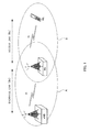
- FIG. 1 is a diagram illustrating the outline of the radio relay technique by the layer 3 relay.
- a radio relay station apparatus (RN) of the layer 3 relay is characterized by having a specific cell ID (PCI: Physical Cell ID) different from that of a radio base station apparatus (eNB) in addition to performing user data reproduction processing, modulation/demodulation and coding/decoding processing.
- PCI Physical Cell ID
- eNB radio base station apparatus
- UE mobile terminal apparatus identifies a cell B formed by the radio relay station apparatus as a cell different from a cell A formed by the radio base station apparatus.
- the mobile terminal apparatus regards the radio relay station apparatus as a radio base station apparatus. Accordingly, mobile terminal apparatuses only having LTE functions are also capable of connecting to the radio relay station apparatus.
- CQI Channel Quality Indicator
- HARQ Hybrid Automatic Repeat reQuest
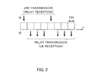
- the radio relay station apparatus when the same frequency (f1) is used to operate, it is necessary to perform Time Division Multiplexing (TDM) on radio resources of the backhaul link and access link (eNB transmission and relay transmission) to control so that transmission and reception is not performed at the same time in the radio relay station apparatus (Non-patent Document 1). Therefore, for example, indownlink, the radio relay station apparatus is not able to transmit a downlink signal to a mobile terminal apparatus for a period during which a downlink signal is received from the radio base station apparatus.
- TDM Time Division Multiplexing
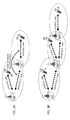
- the radio base station apparatus eNB transmits a downlink signal to a mobile terminal apparatus (UE) via the radio relay station apparatus (RN)
- a radio base station apparatus UE
- RN radio relay station apparatus
- another aspect (multi-hop relay) that the eNB transmits to the UE via a plurality (two in FIG. 3B ) of RNs as shown in FIG. 3(B) .
- the radio relay station apparatus is capable of identifying whether a received signal is a single hop relay signal or a multi-hop relay signal.
- the radio relay station apparatus is not capable of identifying whether a received signal is a multi-hop relay signal.
- the present invention was made in view of such a respect, and it is an object of the invention to provide a radio relay station apparatus and radio relay method for enabling the radio relay station apparatus to identify a multi-hop relay signal and relay a downlink signal suitably.
- a radio relay station apparatus of the invention is characterized by having a reception section configured to receive a control signal indicative of passing through a radio relay station apparatus, a demodulation section configured to demodulate a downlink signal based on the control signal, a modulation section configured to modulate the downlink signal subj ected to demodulation, and a transmission section conf igured to transmit the downlink signal subjected to modulation.
- a radio relay method of the invention is characterized by having the steps, in a first radio relay station apparatus or a radio base station apparatus, of generating a control signal indicative of passing through a radio relay station apparatus, and transmitting the control signal in downlink, and the steps, in a second radio relay station apparatus, of receiving the control signal, demodulating a downlink signal based on the control signal, modulating the downlink signal subjected to demodulation, and transmitting the downlink signal subjected to modulation.
- a first radio relay station apparatus or a radio base station apparatus generates a control signal indicative of passing through a radio relay station apparatus, and transmits the control signal in downlink
- a second radio relay station apparatus receives the control signal, demodulates a downlink signal based on the control signal, modulates the downlink signal subjected to demodulation, and transmits the downlink signal subjected to modulation
- the radio relay station apparatus is thereby capable of identifying whether the signal is a signal of multi-hop relay transmission, and of relaying the downlink signal suitably.
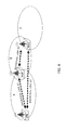
- a cell A is a cell formed by a radio base station apparatus (eNB)
- a cell B is a cell formed by a radio relay station apparatus (RN) #1
- a cell C is a cell formed by a radio relay station apparatus (RN) #2.
- a backhaul link #1 between the eNB and the RN #1 there are a backhaul link #1 between the eNB and the RN #1, a backhaul link #2 between the RN #1 and the RN #2, and a backhaul link #3 between the eNB and the RN #2.
- the RN #2 receives a downlink signal from the eNB via the RN #1 i.e. a downlink signal (multi-hop relay transmission) via the backhaul links #1 and #2, and a downlink signal from the eNB (without passing through the RN) i.e. a downlink signal (single-hop relay transmission) via the backhaul link #3.
- a control signal (control signal for enabling a multi-hop relay transmission to be identified) indicative of passing through the radio relay station apparatus, and this control signal is transmitted to the RN (multi-hop relay transmission is notified.)
- the control signal is preferably multiplexed into a downlink control channel (R-PDCCH: Relay-Physical Downlink Control CHannel) for relay transmission or downlink control channel (PDCCH: Physical Downlink Control CHannel).
- control signal may be multiplexed into a PBCH (Physical Broadcast CHannel) or DBCH (Dynamic Broadcast CHannel) (Higher-layer signaling).
- PBCH Physical Broadcast CHannel
- DBCH Dynamic Broadcast CHannel
- MIB Master Information Block
- control signal may be a signal indicative of whether or not to pass through the radio relay station apparatus, or may be a signal specifically indicative of the number of hops (radio relay station apparatuses via which the signal is passed through).
- the radio relay station apparatus receives a control signal including information on passing through the radio relay station apparatus, and based on the control signal, suitably relays the downlink signal.
- the radio relay station apparatus may combine downlink signals from a plurality of (different) propagation paths. For example, in FIG. 4 , the RN #2 combines a downlink signal of the backhaul link #2 and a downlink signal of the backhaul link #3.
- the RN #2 combines a downlink signal of the backhaul link #2 and a downlink signal of the backhaul link #3.
- a signal with the high number of radio relay station apparatuses (the high number of hops) via which the signal is transmitted has a possibility of increasing a delay in the combined signal, and therefore, may not be combined.
- a downlink signal to relay may be selected from among downlink signals from apluralityofpropagationpaths.
- a downlink signal with the low number of radio relay station apparatuses (the low numberof hops) viawhichthe signal is transmitted may be selected from among downlink signals from a plurality of propagation paths, or a downlink signal with high reception power (or reception SINR (Signal to Interference plus Noise Ratio)) may be selected from among downlink signals from a plurality of propagation paths.
- the downlink signal of the backhaul link #3 may be selected so as to decrease the number of hops (decrease a delay), and this downlink signal may be only relayed.
- reception power (or reception SINR) of the downlink signal of the backhaul link #2 is higher than reception power (or reception SINR) of the downlink signal of the backhaul link #3
- the downlink signal of the backhaul link #2 may be selected so as to achieve higher throughput, and this downlink signal may be only relayed.
- the radio relay station apparatus may select a combined signal subjected to combining of downlink signals from a plurality of (different) propagation paths, and relay the combined signal as a downlink signal. For example, in FIG. 4 , the radio relay station apparatus may relay a combined signal of the downlink signal of the backhaul link #2 and the downlink signal of the backhaul link #3.
- a downlink signal to relay may be selected from among downlink signals from a plurality of propagation paths, without depending on a control signal indicative of passing through the radio relay station apparatus.
- a downlink signal with high reception power (or reception SINR) may be selected from among downlink signals from a plurality of propagation paths, or a threshold of reception power (or reception SINR) may be beforehand set to select only a downlink signal exceeding the threshold. For example, in FIG.
- a reception signal level of the downlink signal of the backhaul link #2 is compared with a reception signal level of the downlink signal of the backhaul link #3, and the downlink signal of the backhaul link #2 with higher reception power may be selected so as to relay only the downlink signal.
- a threshold is compared with a reception signal level of the downlink signal of the backhaul link #2 and a reception signal level of the downlink signal of the backhaul link #3, and a downlink signal exceeding the threshold may be selected so as to relay only the downlink signal.
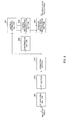
- FIG. 5 is a block diagram illustrating a schematic configuration of a transmission side of the radio relay station apparatus according to Embodiments of the invention.
- the configuration as shown in FIG. 5 is the same as a configuration of the transmission side of the radio base station apparatus.
- the transmission side of the radio relay station apparatus as shown in FIG. 5 is mainly comprised of a data signal generating section 501, channel coding sections 502, 507, modulation sections 503, 508, mapping section 504, control signal generating section 505, downlink control information generating section 506, control channel multiplexing section 509, interleave section 510, reference signal generating section 511, IFFT (Inverse Fast Fourier Transform) section 512, and CP (Cyclic Prefix) inserting section 513.
- IFFT Inverse Fast Fourier Transform
- CP Cyclic Prefix
- the data signal generating section 501 generates a data signal of downlink to be transmitted to a relay node (RN) and a data signal of downlink to be transmitted to a relay UE (mobile terminal apparatus under control of the relay node).
- the data signal generating section 501 outputs the downlink data signals to the channel coding section 502.
- the channel coding section 502 performs channel coding on the downlink data signal.
- the channel coding section 502 outputs the channel-coded data signal to the modulation section 503.
- the modulation section 503 modulates channel-coded data.
- the modulation section 503 outputs the data-modulated data signal to the mapping section 504.
- the mapping section 504 maps the signal in the frequency domain to subcarriers based on resource allocation information.
- the mapping section 504 outputs the mapped data signal to the IFFT section 512.
- the control signal generating section 505 generates a control signal indicative of passing through the radio relay station apparatus. It is essential only that the control signal in this case is a signal indicative of whether a signal is transmitted via the radio relay station apparatus.
- the control signal may be a signal (flag) of 1 bit indicative of whether or not to pass through the radio relay station apparatus, or a signal indicative of the number of radio relay station apparatuses via which a signal is transmitted.
- the control signal generating section 505 outputs the control signal to the downlink control information generating section 506.
- the downlink control information generating section 506 generates downlink control information to be transmitted on the R-PDCCH or PDCCH.
- the downlink control information generating section 506 outputs the downlink control information to the channel coding section 507.
- the channel coding section 507 performs channel coding on the downlink control information.
- the channel coding section 507 outputs the channel-coded downlink control information to the modulation section 508.
- the modulation section 508 modulates the channel-coded downlink control information.
- the modulation section 508 outputs the data-modulated downlink control information to the control channel multiplexing section 509.
- the control channel multiplexing section 509 multiplexes the downlink control information and control signal into the R-PDCCH or PDCCH.
- the control channel multiplexing section 509 outputs the multiplexed signal to the interleave section 510.
- the interleave section 510 interleaves the control channel signal multiplexed into the control channel.
- the interleave section 510 outputs the interleaved signal to the IFFT section 512.
- the reference signal generating section 511 generates a reference signal, and outputs the reference signal to the IFFT section 512.
- the IFFT section 512 performs IFFT on the data signal, control channel signal and reference signal to transform into the signal in the time domain.
- the IFFT section 512 outputs the IFFT-processed signal to the CP inserting section 513.
- the CP inserting section 513 inserts a CP in the IFFT-processed signal.
- the signal with the CP inserted is transmitted in downlink in the backhaul link.
- FIG. 6 is a block diagram illustrating a schematic configuration of a reception side of the radio relay station apparatus according to Embodiment 1 of the invention.
- the radio relay station apparatus as shown in FIG. 6 has a CP removing section 601, FFT (Fast Fourier Transform) section 602, demapping section 603, downlink shared data demodulation section 604, deinterleave section 605, control information demodulation section 606, and channel estimation section 607.
- FFT Fast Fourier Transform
- the CP removing section 601 removes a CP from a reception signal.
- the CP removing section 601 outputs the CP-removed signal to the FFT section 602.
- the FFT section 602 performs FFT processing on the CP-removed signal.
- the FFT section 602 outputs the FFT-processed signal to the demapping section 603.
- the demapping section 603 demaps the FFT-processed signal, and outputs the demapped signal to the downlink shared data demodulation section 604, while outputting the signal to the deinterleave section 605 and the channel estimation section 607.
- the channel estimation section 607 performs channel estimation using a reference signal, and outputs the channel estimation value to the downlink shared data demodulation section 604 and the control information demodulation section 606.
- the deinterleave section 605 deinterleaves the demapped signal.
- the deinterleave section 605 outputs the deinterleaved signal to the control information demodulation section 606.
- the control information demodulation section 606 modulates the control information including the downlink control information and control signal using the channel estimation value obtained in the channel estimation section 607. By this means, it is possible to demodulate the control signal indicative of passing through the radio relay station apparatus, and on the received downlink signal, it is possible to identify whether the downlink signal is transmitted via the radio relay station apparatus (or the number of times the downlink signal is transmitted via the radio relay station apparatus (the number of hops)).
- the control information demodulation section 606 outputs the demodulated downlink control information and control signal to the downlink shared data demodulation section 604.
- the downlink shared data demodulation section 604 demodulates a downlink shared data signal using the channel estimation value obtained in the channel estimation section 607.
- obtained data signal is subjected to channel coding again, modulated, and then, is transmitted to the relay UE or another RN as a downlink signal.
- a radio relay method by the radio relay station apparatus having the above-mentioned configuration a first radio relay station apparatus or a radio base station apparatus generates a control signal indicative of passing through a radio relay station apparatus, and transmits the control signal in downlink, and a second radio relay station apparatus receives the control signal, demodulates a downlink signal based on the control signal, modulates the downlink signal subjected to demodulation, and transmits the downlink signal subjected to modulation.
- the control signal generating section 505 generates a control signal indicative of passing through the radio relay station apparatus.
- the section 505 since the downlink signal is not transmitted via any radio relay station apparatus, the section 505 generates a control signal (for example, bit "0") indicative of not passing through any radio relay station apparatus.
- a signal with the control signal multiplexed thereinto is transmitted to the RN #1 or RN #2 on the R-PDCCH or PDCCH of the backhaul link #1 or backhaul link #3.
- the control information demodulation section 606 demodulates the control signal (for example, bit "0") indicative of not passing through any radio relay station apparatus.
- the RN #1 or RN #2 is capable of identifying that the downlink signal received from the eNB is not via any radio relay station apparatus.
- the downlink shared data demodulation section 604 of the RN #1 or RN #2 demodulates a downlink shared data signal transmitted on the R-PDCCH or PDCCH of the backhaul link #1 or backhaul link #3.
- the RN #1 or RN #2 performs suitable processing on the demodulated downlink shared data signal, and transmits the downlink shared data signal to another RN or relay
- the control signal generating section 505 generates a control signal indicative of passing through the radio relay station apparatus.
- the section 505 since the downlink signal is transmitted via the radio relay station apparatus, the section 505 generates a control signal (for example, bit "1") indicative of passing through the radio relay station apparatus.
- a signal with the control signal multiplexed thereinto is transmitted to the RN #2 on the R-PDCCH or PDCCH of the backhaul link #2.
- the control information demodulation section 606 demodulates the control signal (for example, bit "1") indicative of passing through the radio relay station apparatus.
- the RN #2 is capable of identifying that the downlink signal received from the RN #1 is via the radio relay station apparatus. Further, the downlink shared data demodulation section 604 of the RN #2 demodulates a downlink shared data signal transmitted on the R-PDCCH or PDCCH of the backhaul link #2. Subsequently, based on the control signal (in consideration of passing through the radio relay station apparatus), when necessary, the RN #2 performs suitable processing on the demodulated downlink shared data signal, performs channel coding and modulation again, and then, transmits the downlink shared data signal to another RN or relay UE.
- a first radio relay station apparatus or a radio base station apparatus generates a control signal indicative of passing through a radio relay station apparatus, and transmits the control signal in downlink
- a second radio relay station apparatus receives the control signal, demodulates a downlink signal based on the control signal, modulates the demodulated downlink signal, transmits the modulated downlink signal, and is thereby capable of identifying whether the signal is a signal of multi-hop relay transmission, and of relaying the downlink signal suitably.
- This Embodiment describes the case that a radio relay station apparatus combines downlink signals from a plurality of (different) propagation paths based on a control signal.
- a configuration of a transmission side of the radio relay station apparatus in this Embodiment is the same as the configuration as shown in FIG. 5 .
- FIG. 7 is a block diagram illustrating a schematic configuration of a reception side of the radio relay station apparatus according to Embodiment 2 of the invention.
- the radio relay station apparatus as shown in FIG. 7 is provided with a downlink shared data combining section 608 that combines a plurality of downlink shared data signals demodulated in the downlink shared data demodulation section 604.
- the downlink shared data combining section 608 combines downlink shared data signals of different propagation paths.
- combined data signal undergoes channel coding again, is modulated, and then, is transmitted to a relay UE or another RN as a downlink signal. Since a signal with the high number of radio relay station apparatuses (the high number of hops) via which the signal is transmitted has a possibility of increasing a delay in the combined signal, the downlink shared data combining section 608 may not combine the signal.
- the control signal generating sections 505 in the eNB and RN #1 generate a control signal indicative of whether or not to pass through the radio relay stationapparatus.
- the section 505 since the downlink signal is not transmitted via any radio relay station apparatus, the section 505 generates a control signal (for example, bit "0" ) indicative of not passing through any radio relay station apparatus.
- the section 505 since the downlink signal is transmitted via the radio relay station apparatus, the section 505 generates a control signal (for example, bit "1") indicative of passing through the radio relay station apparatus.
- a signal with the control signal multiplexed thereinto is transmitted to the RN #2 on the R-PDCCH or PDCCH of the backhaul link #2 or backhaul link #3.
- the control information demodulation section 606 demodulates the control signal (for example, bit "0", bit "1") indicates of whether or not to pass through the radio relay station apparatus.
- the downlink shared data demodulation section 604 of the RN #2 demodulates a downlink shared data signal transmitted on the R-PDCCH or PDCCH of the backhaul link #2 or backhaul link #3.
- the downlink shared data combining section 608 combines the downlink shared data signal received via the backhaul link #2 and the downlink shared data signal received via the backhaul link #3. At this point, it is preferable that the downlink shared data combining section 608 determines whether to combine a plurality of downlink shared data signals based on the control signal indicative of whether or not to pass through the radio relaystationapparatus. Inotherwords, when the control signal includes the information indicative of the number of hops, the section 608 is capable of eliminating a signal with the high number of radio relay station apparatuses (the higher number of hops) via which the signal is transmitted, and combining signals with the low number of hops. Bythismeans, it is possible to achieve high reception quality. Subsequently, the RN #2 performs channel coding and modulation again, and transmits the downlink shared data signal to another RN or relay UE.
- a first radio relay station apparatus or a radio base station apparatus generates a control signal indicative of passing through a radio relay station apparatus, and transmits the control signal in downlink
- a second radio relay station apparatus receives the control signal, demodulates a downlink signal based on the control signal, combines demodulated downlink signals, then modulates, transmits the modulated downlink signal, and is thereby capable of identifying whether the signal is a signal of multi-hop relay transmission, and of relaying the downlink signal suitably, while achieving high reception quality.
- This Embodiment describes the case that a radio relay station apparatus selects a downlink signal to relay from among downlink signals from a plurality of propagation paths based on a control signal.
- a configuration of a transmission side of the radio relay station apparatus in this Embodiment is the same as the configuration as shown in FIG. 5 .
- FIG. 8 is a block diagram illustrating a schematic configuration of a reception side of the radio relay station apparatus according to Embodiment 3 of the invention.
- the radio relay station apparatus as shown in FIG. 8 is provided with a downlink shared demodulation data selecting section 609 that selects a downlink signal to relay from among downlink signals from a plurality of propagation paths based on a control signal indicative of passing through a radio relay station apparatus, and a reception power determining section 610 that determines reception power of a reception signal.
- the downlink shared demodulation data selecting section 609 selects a downlink shared demodulation data signal to relay from among downlink shared demodulation data signals from a plurality of propagation paths.
- the downlink shared demodulation data selecting section 609 selects a downlink shared demodulation data signal with the low number of radio relay station apparatuses (the low number of hops) via which the signal is transmitted from among downlink shared demodulation data signals from a plurality of propagation paths. By this means, it is possible to relay a shared demodulation data signal with a low delay.
- the downlink shared demodulation data selecting section 609 outputs selection information of downlink shared demodulation data to the downlink shared data demodulation section 604.
- the reception power determining section 610 determines reception power of downlink signals from a plurality of propagation paths, and outputs the reception power to the downlink shared demodulation data selecting section 609.
- the downlink shared demodulation data selecting section 609 may select a downlink shared demodulation data signal with high reception power from among downlink shared demodulation data signals from a plurality of propagation paths. In this case, it is preferable that the downlink shared demodulation data selecting section 609 selects a downlink shared demodulation data signal while considering both the number of radio relay station apparatuses (the number of hops) via which the signal is transmitted and reception power. By this means, it is possible to relay a shared demodulation data signal with high reception quality.
- this Embodiment describes the case of using reception power as a selection criterion parameter, but the invention is not limited thereto, and allows the reception SINR to be used as a selection criterion parameter.
- the control signal generating sections 505 in the eNB and RN #1 generate a control signal indicative of whether or not to pass through the radio relay stationapparatus.
- the section 505 since the downlink signal is not transmitted via any radio relay station apparatus, the section 505 generates a control signal (for example, bit "0") indicative of not passing through any radio relay station apparatus.
- the section 505 since the downlink signal is transmitted via the radio relay station apparatus, the section 505 generates a control signal (for example, bit "1") indicative of passing through the radio relay station apparatus.
- a signal with the control signal multiplexed thereinto is transmitted to the RN #2 on the R-PDCCH or PDCCH of the backhaul link #2 or backhaul link #3.
- the control information demodulation section 606 demodulates the control signal (for example, bit "0" or bit "1") indicative of whether or not to pass through the radio relay station apparatus.
- the downlink shared demodulation data selecting section 609 selects the downlink shared data signal of the backhaul link #3 from the downlink shared data signal of the backhaul link #2 and the downlink shared data signal of the backhaul link #3 so that the number of hops is lower (the delay is smaller).
- the downlink shared demodulation data selecting section 609 selects the downlink shared data signal of the backhaul link #2 so as to enable higher throughput to be achieved.
- the downlink shared data demodulation section 604 of the RN #2 demodulates the downlink shared data signal selected in the downlink shared demodulation data selecting section 609.
- the section 604 demodulates only the downlink shared data signal of the backhaul link #3 in selecting so as to decrease the number of hops, while demodulating only the downlink shared data signal of the backhaul link #2 in selecting so as to achieve higher throughput.
- the RN #2 performs channel coding and modulation again, and then, transmits the downlink shared data signal to another RN or relay UE.
- a first radio relay station apparatus or a radio base station apparatus generates a control signal indicative of passing through a radio relay station apparatus, and transmits the control signal in downlink
- a second radio relay station apparatus receives the control signal, demodulates a downlink signal based on the control signal, selects the demodulated downlink signal, then modulates, transmits the modulated downlink signal, and is thereby capable of identifying whether the signal is a signal of multi-hop relay transmission, and of relaying the downlink signal suitably.
- This Embodiment describes the case that a radio relay station apparatus selects a downlink signal to relay from among downlink signals from a plurality of propagation paths without depending on a control signal.
- Aconfigurationofatransmission side of the radio relay station apparatus in this Embodiment is the same as the configuration as shown in FIG. 5 except that the control signal generating section 505 is not provided.
- FIG. 9 is a block diagram illustrating a schematic configuration of a reception side of the radio relay station apparatus according to Embodiment 4 of the invention.
- the radio relay station apparatus as shown in FIG. 9 is provided with the downlink shared demodulation data selecting section 609 that selects a downlink signal to relay from among downlink signals from a plurality of propagation paths based on a control signal indicative of passing through a radio relay station apparatus, and the reception power determining section 610 that determines reception power of a reception signal.
- the reception power determining section 610 determines reception power of downlink shared data signals from a plurality of propagation paths, and outputs the reception power to the downlink shared demodulation data selecting section 609.
- the downlink shared demodulation data selecting section 609 selects a downlink shared demodulation data signal with high reception power from among downlink shared demodulation data signals from a plurality of propagation paths. By this means, it is possible to relay a shared demodulation data signal with higher reception quality.
- the downlink shared demodulation data selecting section 609 outputs selection information of downlink shared demodulation data to the downlink shared data demodulation section 604.
- this Embodiment describes the case of using reception power as a selection criterion parameter, but the invention is not limited thereto, and allows the reception SINR to be used as a selection criterion parameter.
- the reception power determining section 610 determines (measures) reception power of downlink shared data signals from a plurality of propagation paths. Based on the reception power, the downlink shared demodulation data selecting section 609 selects a downlink shared data signal to demodulate.
- reception power of the downlink signal of the backhaul link #2 is higher than reception power of the downlink shared data signal of the backhaul link #3
- a reception signal level of the downlink shared data signal of the backhaul link #2 is compared with a reception signal level of the downlink shared data signal of the backhaul link #3, and the downlink shared data signal of the backhaul link #2 with higher reception power is selected.
- the downlink shared data demodulation section 604 demodulates the downlink shared data signal selected in the downlink shared demodulation data selecting section 609.
- the RN #2 performs channel coding and modulation again, and then, transmits the downlink shared data signal to another RN or relay UE.
- the radio relay station apparatus demodulates a downlink signal, measures reception quality (reception power or reception SINR), selects the demodulated downlink signal based on the reception quality, then modulates, transmits the modulated downlink signal, and is thereby capable of relaying the downlink signal suitably.
- reception quality reception power or reception SINR
- Embodiments 1 to 4 describe the case that the number of propagation paths reaching the RN is two, but the invention is not limited thereto, and is similarly applicable to the case that the number of propagation paths reaching the RN is three or more.
- Embodiments disclosed this time are illustrative in all the respects, and the present invention is not limited to the Embodiments.
- the scope of the invention is indicated by the scope of the claims rather than by the descriptions of only the above-mentioned Embodiments, and is intended to include senses equal to the scope of the claims and all modifications within the scope of the claims.
- the present invention is useful in radio relay station apparatuses and radio relay methods in the LTE-A system.
Landscapes
- Engineering & Computer Science (AREA)
- Computer Networks & Wireless Communication (AREA)
- Signal Processing (AREA)
- Mobile Radio Communication Systems (AREA)
- Radio Relay Systems (AREA)
Applications Claiming Priority (2)
| Application Number | Priority Date | Filing Date | Title |
|---|---|---|---|
| JP2010140337A JP5454792B2 (ja) | 2010-06-21 | 2010-06-21 | 無線中継局装置及び無線中継方法 |
| PCT/JP2011/063741 WO2011162143A1 (fr) | 2010-06-21 | 2011-06-15 | Dispositif de station relais radio et procédé de relais radio |
Publications (2)
| Publication Number | Publication Date |
|---|---|
| EP2584840A1 true EP2584840A1 (fr) | 2013-04-24 |
| EP2584840A4 EP2584840A4 (fr) | 2017-05-03 |
Family
ID=45371336
Family Applications (1)
| Application Number | Title | Priority Date | Filing Date |
|---|---|---|---|
| EP11798029.2A Withdrawn EP2584840A4 (fr) | 2010-06-21 | 2011-06-15 | Dispositif de station relais radio et procédé de relais radio |
Country Status (4)
| Country | Link |
|---|---|
| US (1) | US9037076B2 (fr) |
| EP (1) | EP2584840A4 (fr) |
| JP (1) | JP5454792B2 (fr) |
| WO (1) | WO2011162143A1 (fr) |
Families Citing this family (10)
| Publication number | Priority date | Publication date | Assignee | Title |
|---|---|---|---|---|
| JP6040467B2 (ja) * | 2013-02-07 | 2016-12-07 | アイディーエーシー ホールディングス インコーポレイテッド | 低レイテンシミリ波(mmw)バックホールシステムのための物理層(phy)設計 |
| AU2015331962B2 (en) * | 2014-10-15 | 2018-05-10 | Nec Corporation | Radio relay station, radio base station, communication system and communication method |
| US10171214B2 (en) | 2016-09-29 | 2019-01-01 | At&T Intellectual Property I, L.P. | Channel state information framework design for 5G multiple input multiple output transmissions |
| US10644924B2 (en) | 2016-09-29 | 2020-05-05 | At&T Intellectual Property I, L.P. | Facilitating a two-stage downlink control channel in a wireless communication system |
| US10206232B2 (en) | 2016-09-29 | 2019-02-12 | At&T Intellectual Property I, L.P. | Initial access and radio resource management for integrated access and backhaul (IAB) wireless networks |
| US10602507B2 (en) | 2016-09-29 | 2020-03-24 | At&T Intellectual Property I, L.P. | Facilitating uplink communication waveform selection |
| US10158555B2 (en) | 2016-09-29 | 2018-12-18 | At&T Intellectual Property I, L.P. | Facilitation of route optimization for a 5G network or other next generation network |
| US10355813B2 (en) | 2017-02-14 | 2019-07-16 | At&T Intellectual Property I, L.P. | Link adaptation on downlink control channel in a wireless communications system |
| JP7268745B2 (ja) * | 2019-08-23 | 2023-05-08 | 日本電信電話株式会社 | 無線通信装置および無線通信方法 |
| US20220369120A1 (en) * | 2019-08-23 | 2022-11-17 | Nippon Telegraph And Telephone Corporation | Radio communication apparatus, and radio communication method |
Family Cites Families (16)
| Publication number | Priority date | Publication date | Assignee | Title |
|---|---|---|---|---|
| WO2001041326A1 (fr) * | 1999-11-29 | 2001-06-07 | Commonwealth Scientific And Industrial Research Organisation | Systeme de communications |
| US20040105382A1 (en) * | 2000-05-25 | 2004-06-03 | Kenichi Miyoshi | Radio reception apparatus |
| JP2002026923A (ja) * | 2000-07-06 | 2002-01-25 | Nippon Hoso Kyokai <Nhk> | 自己増殖型無線分配ネットワーク |
| US7408929B2 (en) * | 2001-09-28 | 2008-08-05 | Kabushiki Kaisha Toshiba | Radio communication system, terminal and packet |
| JP2003332963A (ja) * | 2002-05-17 | 2003-11-21 | Toshiba Corp | 無線通信システム及び無線通信装置 |
| US7702280B2 (en) * | 2002-05-27 | 2010-04-20 | Ntt Docomo, Inc. | Mobile communication system, transmission station, reception station, relay station, communication path deciding method, and communication path deciding program |
| US7072612B2 (en) * | 2003-03-03 | 2006-07-04 | Qualcomm Incorporated | Repeater identification in position determination system |
| CN101091333A (zh) * | 2004-12-27 | 2007-12-19 | 松下电器产业株式会社 | 无线通讯装置、无线通讯方法和无线通讯系统 |
| JP2006246202A (ja) * | 2005-03-04 | 2006-09-14 | Nec Corp | 最適中継ノード選択方法、ノード及びマルチホップ無線通信ネットワークシステム |
| JP4734323B2 (ja) * | 2005-03-29 | 2011-07-27 | パナソニック株式会社 | 通信中継装置、受信装置、通信中継方法及び受信方法 |
| EP1863211B1 (fr) * | 2006-05-29 | 2013-10-16 | Samsung Electronics Co., Ltd. | Appareil et procédé de retransmission dans un système de communication relais sans fil |
| KR101248071B1 (ko) * | 2006-09-06 | 2013-03-27 | 삼성전자주식회사 | 멀티 홉 기술을 지원하는 광대역 무선 통신 시스템에서재전송 방법 및 장치 |
| KR101108956B1 (ko) * | 2007-07-13 | 2012-02-09 | 엘지전자 주식회사 | 협동 통신 네트워크에서 전력 밸런싱 |
| US8605643B2 (en) * | 2008-03-14 | 2013-12-10 | Samsung Electronics Co., Ltd. | Apparatus and method for retransmitting of data in a wireless communication system using relay |
| EP2352327A4 (fr) * | 2008-10-31 | 2012-05-02 | Fujitsu Ltd | Procédé, système et dispositif de communication radio réutilisant une ressource de canal |
| EP2416504A1 (fr) * | 2009-03-31 | 2012-02-08 | Panasonic Corporation | Appareil de relais et procédé de relais |
-
2010
- 2010-06-21 JP JP2010140337A patent/JP5454792B2/ja not_active Expired - Fee Related
-
2011
- 2011-06-15 WO PCT/JP2011/063741 patent/WO2011162143A1/fr not_active Ceased
- 2011-06-15 US US13/703,375 patent/US9037076B2/en not_active Expired - Fee Related
- 2011-06-15 EP EP11798029.2A patent/EP2584840A4/fr not_active Withdrawn
Also Published As
| Publication number | Publication date |
|---|---|
| JP2012005014A (ja) | 2012-01-05 |
| EP2584840A4 (fr) | 2017-05-03 |
| US9037076B2 (en) | 2015-05-19 |
| US20130109297A1 (en) | 2013-05-02 |
| JP5454792B2 (ja) | 2014-03-26 |
| WO2011162143A1 (fr) | 2011-12-29 |
Similar Documents
| Publication | Publication Date | Title |
|---|---|---|
| US9037076B2 (en) | Radio relay station apparatus and radio relay method | |
| JP5172885B2 (ja) | 無線中継局装置、無線基地局装置及びリレー周波数割り当て方法 | |
| US20130094433A1 (en) | Radio relay station apparatus and mobile terminal apparatus | |
| US8422941B2 (en) | Radio communication method | |
| US8811257B2 (en) | Mobile communication system, relay station apparatus, base station apparatus, radio relay method, and computer readable medium | |
| US20130201902A1 (en) | Radio base station apparatus and resource allocation method | |
| WO2011036965A1 (fr) | Système de communication, dispositif de relais, terminal de communication et station de base | |
| KR20110044901A (ko) | 무선 통신 네트워크에서의 다운링크 투명 중계를 가능하게 하는 방법 | |
| US8811261B2 (en) | Radio base station apparatus, radio relay station apparatus, and resource allocation method | |
| WO2012077790A1 (fr) | Station relais sans fil, station de base sans fil et procédé de communication sans fil | |
| EP2627114A1 (fr) | Procédé d'émission relais, et station relais | |
| JP5249983B2 (ja) | 無線基地局装置、移動端末装置及びセル選択方法 | |
| KR20110082059A (ko) | 다운링크에서의 사용자 장비에 적합한 중계 기법 | |
| JP5249999B2 (ja) | リレー伝送方法、リレー局及び無線基地局 | |
| WO2010122869A1 (fr) | Appareil de station de base, appareil de station relais, et système de communication mobile |
Legal Events
| Date | Code | Title | Description |
|---|---|---|---|
| PUAI | Public reference made under article 153(3) epc to a published international application that has entered the european phase |
Free format text: ORIGINAL CODE: 0009012 |
|
| 17P | Request for examination filed |
Effective date: 20121214 |
|
| AK | Designated contracting states |
Kind code of ref document: A1 Designated state(s): AL AT BE BG CH CY CZ DE DK EE ES FI FR GB GR HR HU IE IS IT LI LT LU LV MC MK MT NL NO PL PT RO RS SE SI SK SM TR |
|
| DAX | Request for extension of the european patent (deleted) | ||
| RA4 | Supplementary search report drawn up and despatched (corrected) |
Effective date: 20170331 |
|
| RIC1 | Information provided on ipc code assigned before grant |
Ipc: H04B 7/15 20060101AFI20170327BHEP |
|
| STAA | Information on the status of an ep patent application or granted ep patent |
Free format text: STATUS: THE APPLICATION HAS BEEN WITHDRAWN |
|
| 18W | Application withdrawn |
Effective date: 20180813 |