EP2585633B1 - Caisse de tête pour une machine de production d'une bande de matière fibreuse - Google Patents
Caisse de tête pour une machine de production d'une bande de matière fibreuse Download PDFInfo
- Publication number
- EP2585633B1 EP2585633B1 EP11710757.3A EP11710757A EP2585633B1 EP 2585633 B1 EP2585633 B1 EP 2585633B1 EP 11710757 A EP11710757 A EP 11710757A EP 2585633 B1 EP2585633 B1 EP 2585633B1
- Authority
- EP
- European Patent Office
- Prior art keywords
- headbox
- fibrous material
- generating means
- cross
- material suspension
- Prior art date
- Legal status (The legal status is an assumption and is not a legal conclusion. Google has not performed a legal analysis and makes no representation as to the accuracy of the status listed.)
- Active
Links
Images



Classifications
-
- D—TEXTILES; PAPER
- D21—PAPER-MAKING; PRODUCTION OF CELLULOSE
- D21F—PAPER-MAKING MACHINES; METHODS OF PRODUCING PAPER THEREON
- D21F1/00—Wet end of machines for making continuous webs of paper
- D21F1/02—Head boxes of Fourdrinier machines
-
- D—TEXTILES; PAPER
- D21—PAPER-MAKING; PRODUCTION OF CELLULOSE
- D21F—PAPER-MAKING MACHINES; METHODS OF PRODUCING PAPER THEREON
- D21F1/00—Wet end of machines for making continuous webs of paper
- D21F1/02—Head boxes of Fourdrinier machines
- D21F1/022—Means for injecting material into flow within the headbox
-
- D—TEXTILES; PAPER
- D21—PAPER-MAKING; PRODUCTION OF CELLULOSE
- D21F—PAPER-MAKING MACHINES; METHODS OF PRODUCING PAPER THEREON
- D21F1/00—Wet end of machines for making continuous webs of paper
- D21F1/02—Head boxes of Fourdrinier machines
- D21F1/024—Details of the feed chamber
-
- D—TEXTILES; PAPER
- D21—PAPER-MAKING; PRODUCTION OF CELLULOSE
- D21F—PAPER-MAKING MACHINES; METHODS OF PRODUCING PAPER THEREON
- D21F1/00—Wet end of machines for making continuous webs of paper
- D21F1/02—Head boxes of Fourdrinier machines
- D21F1/026—Details of the turbulence section
-
- D—TEXTILES; PAPER
- D21—PAPER-MAKING; PRODUCTION OF CELLULOSE
- D21F—PAPER-MAKING MACHINES; METHODS OF PRODUCING PAPER THEREON
- D21F1/00—Wet end of machines for making continuous webs of paper
- D21F1/06—Regulating pulp flow
-
- D—TEXTILES; PAPER
- D21—PAPER-MAKING; PRODUCTION OF CELLULOSE
- D21F—PAPER-MAKING MACHINES; METHODS OF PRODUCING PAPER THEREON
- D21F1/00—Wet end of machines for making continuous webs of paper
- D21F1/08—Regulating consistency
Definitions
- the invention relates to a headbox for a machine for producing a fibrous web, in particular a paper, board or packaging paper web, from at least one pulp suspension, comprising a supplying the at least one pulp suspension and a transverse distributor tube feeding device, with a downstream and a plurality of in an in-line, across the width of the headbox extending intermediate channel, with a downstream turbulence generating means having a plurality of arranged in rows and in columns flow channels, and with the turbulence generating means immediately adjacent and a nozzle gap having headbox, wherein the between the Verteilrohrlochplatte (5) and the turbulence generating means (8) arranged intermediate channel (7) has a free Zw ischenkanalcolo (7.L) of ⁇ 50 mm, preferably of ⁇ 120 mm, in particular of ⁇ 200 mm.
- Such a headbox is for example from the document DE 198 43 729 A1 known.
- the pulp suspension coming from a constant part known to the person skilled in the art is passed through the transverse distributor tube, then deflected in front of or in the distributor tube plate in the machine direction (MD), separated and fed to the machine-width intermediate channel.
- MD machine direction
- the flow ie at least the pulp suspension is uniformed, any added dilution water, in particular white water, is mixed in and the entire suspension is fluidized.
- cross machine direction CD
- the suspension is finally accelerated to machine speed.
- a disadvantage of such a headbox is that its transverse distribution tube is provided with a return system for excess pulp suspension (cf. FIG. 4a ).
- This feedback system usually has a return line and a flow control, comprising a control unit including at least one sensor (pressure sensor), at least one actuator (spool) and various lines on.
- a return system causes incalculable costs in both purchase, operation and maintenance, and it is also sluggish in function and prone to repairs.
- a headbox whose pressure loss in the turbulence generating means is greater than 0.3 bar, preferably greater than 0.2 bar, and the transverse distribution tube has a tapered in the flow direction of the pulp suspension cross-section and connected only in the region of its largest cross-section to a supply line for the pulp suspension is.
- the pulp suspension fed to the transverse distribution tube is discharged exclusively via the headbox nozzle.
- the document EP1676950 A1 discloses a headbox for a machine for making a fibrous web having a distributor for distributing at least one pulp suspension across the machine width.
- the headbox has a first and a second guide device, each having a plurality of channels. Between the guide means an intermediate chamber is provided. Furthermore, the headbox has supply lines for a fluid to be mixed in across the width of the machine, with the supply lines leading into the intermediate chamber.
- the pressure loss for preferably uniform distribution of the pulp suspension should be as low as possible and optimally distributed.
- the energy consumption of the headbox noticeably reduced, the stability of the fiber orientation (transverse) profile improved and the consumption of chemicals, in particular retention agents are reduced.
- a system pressure loss is provided, which is composed essentially of a first pressure loss between the feeder and the intermediate channel and a second pressure loss in the turbulence generating means, wherein the first pressure loss is a value in Range from 15 to 85%, preferably from 25 to 85%, in particular from 40 to 85%, and in that the cross-sectional ratio between inlet and intermediate channel has a value in the range from 0.1 to 2, preferably from 0.15 to 1, 5, in particular from 0.2 to 1, assumes.
- the inventive design of the headbox of the type mentioned provides a most extensive, preferably complete avoidance of the aforementioned disadvantages of the prior art and a significantly improved fulfillment of particular technological requirements.
- the headbox according to the invention achieves a flow in the cross-machine direction as constant as possible inflow of pulp suspension in the headbox. This is made possible above all by the fact that its operation takes place without recirculation, there is a special pressure loss distribution between its headbox areas and there is a minimum distance, ie a minimum length of the intermediate channel, between the two grids, ie the distribution well plate and the turbulence generating means.
- the aspect ratio between inlet and intermediate channel favors a very good transverse distribution of at least one pulp suspension in the width direction of the head box according to the invention.
- the cross-section of the inlet is by definition the largest cross-sectional area of the feeder, that is, the initial cross-sectional area of the feeder, especially the transverse divider tube, whereas the cross-section of the intermediate channel is by definition the free cross-sectional area of the machine-width intermediate chamber, ie the downstream total area of the distribution well plate.
- At least one, well-known to those skilled separator, in particular a blade be arranged. If a plurality of separating elements, in particular lamellae, are arranged in the headbox of the headbox according to the invention, then they can have different lengths and possibly also different properties, such as surface contours and the like.
- the second pressure loss in the turbulence-generating means of the head box according to the invention preferably assumes a value in the range from 0.1 to 1.5 bar, preferably from 0.2 to 1.0 bar, in particular from 0.3 to 0.5. This region for the second pressure loss is particularly advantageous with regard to a good and procedurally necessary fluidization of the pulp suspension.
- the head box according to the invention is preferably provided with hydraulic elements for pressure recovery, such as diffusers, stage diffusers or short diffusers.
- This flow guidance allows a trouble-free and clog-free inflow from the transverse distribution pipe into the distribution well plate at a speed of 4-16 m / s. The necessary flow energy must be converted back into pressure energy through the diffusers in the distribution well plate.
- the at least one pulp suspension fed to the feed device of the head box according to the invention is preferably fed exclusively to the downstream flow channels of the distribution tube hole plate.
- a headbox without a recirculation of the pulp suspension can be realized and the amount of pulp suspension at the edge varies to a significant extent less.
- the cross section of the transverse distribution tube tapering in the flow direction of the pulp suspension and the connection of the supply line for the pulp suspension in the area of the largest cross section of the distributor ensure that the pulp suspension is fed to the distribution well plate under approximately equal pressures.
- a plurality of means spaced apart from one another in the width direction of the headbox is provided for preferably controllable metering of a fluid in partial fluid streams into the at least one pulp suspension, the individual means each having a plurality of metering channel opening and opening centerline, includes Zudosierkanälen opening at different heights and connected to a common supply channel.
- the impact point of the opening center line of the individual Zudosierkanalö Stamm on the turbulence generating means is preferably approximately centrally, preferably centrally between the two column planes of two adjacent flow channels.
- the throughput constancy of fluid in the width direction of the headbox according to the invention in the turbulence generating means can be made independent of the amount of pulp suspension which can be differently metered in the width direction of the headbox.
- the metering channel opening of the means for preferably controllable metered addition of the fluid in partial fluid streams into the at least one pulp suspension to the turbulence generating means of the headbox according to the invention preferably has a vertical distance in the range of 2 to 50 mm, preferably 3 to 40 mm, in particular of 5 to 20 mm, on. This distance ranges ensure the necessary mixing quality of the fluid with the pulp suspension, even with different operating parameters, so that the best conditions for the production of a fibrous web with good to very good Quatticiansmerkmaten are given.
- the respective means for preferably regulatable / controllable metering of the fluid in partial fluid streams into the at least one fibrous suspension preferably comprises an injector, as also described in the German patent application DE 10 2008 054 898.7 of 18.12.2008 (Applicant's File: HPA14265 DE - "MJ II-DoS-TE Geometry”). The relevant disclosure content is hereby made the subject of the present description.
- the fluid preferably consists of water, in particular white water or clear water, or of at least one pulp suspension whose concentration differs from the average concentration of the at least one fibrous suspension flowing in the headbox.
- the transverse distribution tube of the headbox according to the invention preferably has at least one removable component in the region of its preferably smallest end-side cross-section, the removable component preferably having a rectangular cross-section.
- This removable component greatly improves the ease of maintenance and cleaning of the headbox. Due to the preferably rectangular cross section, the hydraulic height of the component is maintained. As a result, the reduction of the cross section is only uniaxial.
- the component is preferably designed as a flap part and connected by means of at least one hinge connection and associated attachment to the transverse distribution tube.
- the articulation is upstream, downstream or side mounted.
- Such a hinge connection belongs to the well-known state of the art and has already proven itself in many diverse applications.
- the component may of course also be connected to the distributor by means of a plurality of screw connections or by means of a plurality of slide connections.
- the component is designed according to a further aspect of the invention as a cleaning access for the distributor and / or as a sampling point for pulp suspension.
- the headbox according to the invention can also be designed as a multi-layer headbox with at least one separating element.
- a multilayer fibrous web having different layer qualities, in particular higher-quality outer layers, can be produced.
- the at least one separating element of the multi-layer headbox can have a minimum rigidity both in the longitudinal direction and in the transverse direction, which assumes at least a value of ⁇ 40 N / mm in certain regions.
- the headbox according to the invention is outstandingly suitable for use in a machine for producing a fibrous web, in particular paper, cardboard or packaging paper web.
- the fibrous web produced in the machine with at least one headbox according to the invention has consistently excellent properties, since, among other things, the control of both its fiber orientation transverse profile and its basis weight cross-section is possible.
- FIG. 1 shows a vertical and schematic longitudinal sectional view of a first preferred embodiment of a headbox 1 according to the invention for a machine for producing a fibrous web 3 from a pulp suspension 2 (arrow).
- the illustrated head box 1 according to the invention can of course also be designed as a multilayer headbox, which uses at least two different pulp suspensions for producing the fibrous web 3.
- the fibrous web 3 may in particular be a paper, board or packaging paper web.
- the headbox 1 has a feed device 4 feeding the fibrous stock suspension 2 (arrow) in the form of a transverse distributor tube 4.1 known to the person skilled in the art.
- the feed device 4 is followed downstream by a Verteilrohrlochplatte 5, which has a plurality of arranged in rows Z and in columns S flow channels 6.
- an intermediate channel 7 extending across the width B (arrow) of the head box 1 according to the invention adjoins.
- a turbulence generating means 8 Downstream of the intermediate channel 7 is a turbulence generating means 8 having a plurality of flow channels 9 arranged in rows Z and columns S.
- the pulp suspension 2 (arrow) in the turbulence generating means 8 is divided into pulp suspension partial streams and exits after exiting the turbulence generating means 8 in a machine-wide chamber 10 in a design of a nozzle gap 12 having headbox 11 merged again to allow the formation of a machine-wide fibrous web 3.
- the flow channels 9 are preferably formed in a known manner as thin-walled turbulence tubes and / or turbulence tube inserts with at least partially constant, at least partially diverging, at least partially converging and / or discontinuous cross-sectional areas.
- the expert well-known and not explicitly shown separating element in particular a blade be arranged. If a plurality of separating elements, in particular lamellae, are arranged in the headbox nozzle 11, they can have different lengths and possibly also different properties, such as surface contours and the like.
- the headbox 11 may be provided on the outlet side at least one side with a dashed line indicated aperture 13.
- a system pressure loss p s which essentially comprises a first pressure loss p 1 between the feed device 4 and the intermediate channel 7 and a second pressure loss p 2 in the turbulence generating means 8.
- the first pressure loss p 1 takes a value in the range of 15 to 85%, preferably 25 to 85%, in particular from 40 to 85%
- the second pressure loss p 2 in the turbulence generating means 8 has a value in the range from 0.1 to 1.5 bar, preferably from 0.2 to 1.0 bar, in particular 0.3 to 0.5 bar, assumes (see also FIG. 3 ).
- the intermediate channel 7 arranged between the distribution-pipe perforated plate 5 and the turbulence-generating means 8 has a free intermediate channel length 7.L of ⁇ 50 mm, preferably 120 mm, in particular 200 mm.
- a free intermediate channel length 7.L of the intermediate channel 7 is machine width (see also FIG. 3 ).
- the cross-sectional ratio Q between inlet 4.Z and intermediate channel 7 furthermore assumes a value in the range from 0.1 to 2, preferably from 0.15 to 1.5, in particular from 0.2 to 1 (cf. FIG. 3 ).
- the cross-sectional ratio Q between inlet 4.Z and intermediate channel 7 favors a very good transverse distribution of the at least one pulp suspension 2 in the width direction Y (arrow) of the head box 1 according to the invention.
- the cross section 4.Q of the inlet 4.Z is by definition the largest cross-sectional area 4.Q max of the feeder 4, so the initial cross-sectional area 4.Q max of the feeder 4, in particular the transverse distributor tube 4.1, whereas the cross section 7.Q of the intermediate channel 7 by definition, the free cross-sectional area 7.Q free of the machine-width intermediate chamber 7, ie downstream total area 5.F of the distribution well plate 5 is.
- the pulp suspension 2 (arrow) fed to the feed device 4 is supplied exclusively to the downstream flow channels 6 of the distribution well plate 5.
- FIG. 2 shows a vertical longitudinal sectional view of a preferred embodiment of a Verteillochlochplatte 5 of a headbox 1 according to the invention for a machine for producing a fibrous web from a pulp suspension with different channel cross-sections 6.Q.
- a distribution well plate 5 for example, in the in the FIG. 1 be used inventive headbox 1 shown.
- the distribution well plate 5 has, for example, five rows Z1 to Z5 on flow channels 6 and a plurality of gaps S on flow channels 6. All flow channels 6 have a consistently round channel cross section 6.Q, but in different shapes and configurations. Also, all flow channels 6 are provided on the inlet side with a respective intake chamfer 14 known to the person skilled in the art.
- the flow channels 6 of the two upper lines Z4, Z5 initially have a constant channel cross section 6.Q, which ultimately undergoes a continuous widening 15, in particular a cone 15.1 with a cone angle ⁇ of ⁇ 30 °.
- the flow channel 6 of the middle row Z3 initially again has a constant channel cross section 6.Q, which ultimately experiences two jump-like extensions 16, in particular increments 16.1, 16.2.
- the flow channels 6 of the two lower rows Z1, Z2 initially have again a constant channel cross-section 6.Q, which ultimately experiences only a sudden expansion 17, in particular a step jump 17.1.
- Each individual flow channel 6 of the distribution well plate 5 thus has at least initially a round channel cross section 6.Q with a channel diameter 6.D and then ultimately forms at least one diffuser 18 due to at least one extension 15, 16, 17.
- the mean channel diameter 6.DM of the single flow channel 6 of the distribution well plate 5 and the length 5.L of the distribution well plate 5 are in a ratio of 1: 2 to 1:10, preferably from 1: 3 to 1: 8, in particular from 1: 4 to 1: 5.
- the distribution well plate 5 is thus provided in the manner explained with hydraulic elements for pressure recovery, such as diffusers 18, stage diffusers or short diffusers.
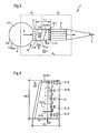
- FIG. 3 now shows a vertical and schematic longitudinal sectional view of a second preferred embodiment of a headbox 1 according to the invention for a machine for producing a fibrous web 3 from a pulp suspension 2 (arrow).
- the illustrated head box 1 according to the invention can of course also be designed as a multilayer headbox, which uses at least two different pulp suspensions for producing the fibrous web 3.
- the fibrous web 3 may in particular be a paper, board or packaging paper web.
- the individual means 19 each comprise a plurality of a metering channel opening 21.O and opening center line 21.M having, at different heights and connected to a common supply channel 22 Zudosierkanäle 21 (see. FIG. 4 ).
- the Zudosierkanalö Stamm 21.O of the individual means 19 for preferably controllable metered addition to the turbulence generating means 8 has a vertical distance A in the range of 2 to 50 mm, preferably from 3 to 40 mm, in particular from 5 to 20 mm.
- the means 19 for preferably controllable metered addition preferably have a pitch width TB of N x 25 mm or N x 33.3 mm, wherein N is preferably a natural number.
- the respective means 19 for preferably regulatable / controllable metering is designed as an injector 19.1.
- the fluid 20 (Peil) consists of water, in particular white water or clear water, or from at least one pulp suspension whose concentration differs from the average concentration of the at least one flowing in the headbox according to the invention pulp suspension.
- FIG. 4 shows a schematic side view of the means 19 for preferably adjustable / controllable metering of a fluid 20 (arrow) of the in the FIG. 3 illustrated headbox 1 of the invention for a machine for producing a fibrous web from a pulp suspension.
- the Zudosierkanal 21 of the means 19 for preferably adjustable / controllable metering connected to the common supply channel 22 moreover has a circular cross-sectional area 21.Q with a diameter 21.D of 2 to 10 mm, preferably of 4 to 6 mm.
- the designed as an injector 19.1 means 19 for preferably controllable metered addition has a length 19.L in the range of 60 to 350 mm, preferably from 100 to 250 mm, and depending on the height of the intermediate chamber of the head box 1 according to the invention a height nineteenth .H in the range of 50 to 300 mm, preferably from 75 to 250 mm.
- the means 19 for preferably controllable metered addition preferably have a pitch width TB of N x 25 mm or N x 33.3 mm, wherein N is preferably a natural number.
- the injector 19.1 is also in the German patent application DE 10 2008 054 898.7 of 18.12.2008 (Applicant's File: HPA14265 DE - "MJ II-DoS-TEGeometrie”). The relevant disclosure content is hereby made the subject of the present description.
- FIG. 5 shows a horizontal, partial and schematic longitudinal section of the in the FIG. 3 illustrated headbox 1 of the invention for a machine for producing a fibrous web 3 from a pulp suspension 2 (arrow).
- the headbox 1 comprises the feeding device 4 feeding the pulp suspension 2 (arrow) in the form of a transverse dividing pipe 4.1 known to the person skilled in the art.
- the feeder 4 is followed downstream of the Verteilrohrlochplatte 5, which has a plurality of arranged in rows Z and in columns S flow channels 6.
- the over the width B (double arrow) of the head box 1 according to the invention extending intermediate channel 7 connects.
- Downstream of the intermediate channel 7 is the turbulence generating means 8 having a plurality of flow channels 9 arranged in rows Z and in gaps S.
- the turbulence generating means 8 is immediately followed by the headbox nozzle 11 having the nozzle gap 12.
- the individual means 19 each comprise a plurality of dispensing channels 21 having a respective dispensing channel opening 21.0 and opening center line 21.M (cf. FIG. 4 ).
- the Zudosierkanalötechnisch 21.O of the individual means 19 for preferably controllable / metered addition to the turbulence generating means 8 has a vertical distance A in the range of 2 to 50 mm, preferably from 3 to 40 mm, in particular from 5 to 20 mm.
- the means 19 for preferably controllable metered addition preferably have a pitch width TB of N x 25 mm or N x 33.3 mm, wherein N is preferably a natural number.
- the transverse distribution pipe 4.1 has a cross-section 4.Q tapering in the direction of flow R (arrow) of the pulp suspension 2 and that it is connected in the region of its largest cross-section to a supply line for the pulp suspension 2 (not shown) but known to a person skilled in the art.
- FIG. 6 shows a schematic front view of a preferred embodiment of a transverse distribution tube 4.1, that is, a feed device 4 of a head box 1 according to the invention.
- the transverse distribution tube 4.1 has at least one removable component 23, which preferably has a rectangular cross section 23.QR.
- the component 23 is designed as a hinged part 23.1, which is connected by means of at least one articulated connection 24 (dash-dot line) and associated attachment to the transverse distribution pipe 4.1.
- the articulation 24 is mounted upstream in the embodiment of FIG 6; However, it can also be mounted downstream or laterally in a further embodiment.
- the component 23, in a manner not shown, may also be connected to the distributor by means of a multiplicity of screw connections or by means of a multiplicity of slide connections.
- FIG. 7 shows a schematic side view of a preferred embodiment of a transverse distribution tube 4.1 of a head box 1 according to the invention.
- the transverse distribution pipe 4.1 has a cross-section 4.Q tapering in the direction of flow R (arrow) of the pulp suspension 2 and, in the region of its largest cross section 4.Q, is connected to an only indicated feed line 25 (arrow) for the pulp suspension 2. Furthermore, the largest cross-sectional area 4.Qmax of the feed device 4, that is to say the initial cross-sectional area 4.Qmax of the feed device 4, in particular of the transverse distributor tube 4.1, is shown.
- the pulp suspension 2 (arrow) supplied to the transverse distribution pipe 4.1 is supplied exclusively to the downstream flow channels 6 of the distribution pipe perforated plate 5.
- transverse distribution pipe 4.1 is shown with a closed and opened component 23 or folding part 23.1, which is connected to the transverse distribution pipe 4.1 by means of the joint connection 24 and associated attachment.
- the Component 23 or folding part 23.1 is preferably designed as a cleaning access and / or as a sampling point.
- FIG. 8 shows an exemplary pressure loss curve in a feed device, in particular in a transverse distribution of a headbox according to the invention for a machine for producing a fibrous web of at least one pulp suspension due to an effective pipe friction.
- the distance from the recirculation side in [mm] on the left ordinate the velocity in the lateral distribution pipe in [m / s] and on the right ordinate the pressure loss dp in [mbar] is plotted.
- At least partially illustrated inventive headbox 1 is particularly suitable for use in a machine for producing a fibrous web 3, in particular paper or board web, from at least one pulp suspension second
- a headbox of the type mentioned above is improved by the invention so that the aforementioned disadvantages of the prior art as far as possible, preferably completely eliminated.
- the pressure loss for preferably uniform distribution of the pulp suspension is distributed as low as possible and optimal.
- the energy consumption of the headbox is significantly reduced, improves the stability of the fiber orientation (transverse) profile and reduces the consumption of chemicals, in particular retention agents.
Landscapes
- Paper (AREA)
Claims (14)
- Caisse de tête (1) pour une machine de fabrication d'une nappe fibreuse (3), en particulier d'une nappe de papier, de carton ou de papier d'emballage, constituée d'au moins une suspension de matière fibreuse (2), avec un dispositif d'alimentation (4) acheminant l'au moins une suspension de matière fibreuse (2) et comprenant un tube distributeur transversal (4.1), avec une plaque perforée de tube distributeur (5) se raccordant en aval et présentant une pluralité de canaux d'écoulement (6) disposés en lignes (Z ; Z1 à Z5) et en colonnes (S), avec un canal intermédiaire (7) situé en aval par rapport à celle-ci, s'étendant sur la largeur (B) de la caisse de tête (1), avec un moyen de génération de turbulence (8) disposé en aval avec une pluralité de canaux d'écoulement (9) disposés en lignes (Z) et en colonnes (S ; S1 à S4), et avec une buse de caisse de tête (11) se raccordant directement au moyen de génération de turbulence (8) et présentant une fente de buse (12), le canal intermédiaire (7) disposé entre la plaque perforée de tube distributeur (5) et le moyen de génération de turbulence (8) présentant une longueur libre de canal intermédiaire (7.L) ≥ 50 mm, de préférence ≥ 120 mm, en particulier ≥ 200 mm,
caractérisée en ce
qu'une perte de pression de système (ps) est prévue, laquelle se compose essentiellement d'une première perte de pression (p1) entre le dispositif d'alimentation (4, 4.1) et le canal intermédiaire (7) et d'une deuxième perte de pression (p2) dans le moyen de génération de turbulence (8), la première perte de pression (p1) prenant une valeur dans la plage de 15 à 85 %, de préférence de 25 à 85 %, en particulier de 40 à 85 %, et en ce que le rapport en section transversale (Q) entre l'entrée (4.Z) et le canal intermédiaire (7) prend une valeur dans la plage de 0,1 à 2, de préférence de 0,15 à 1,5, en particulier de 0,2 à 1. - Caisse de tête (1) selon la revendication 1, caractérisée en ce que
la deuxième perte de pression (p2) dans le moyen de génération de turbulence (8) prend une valeur dans la plage de 0,1 à 1,5 bar, de préférence de 0,2 à 1,0 bar, notamment de 0,3 à 0,5 bar. - Caisse de tête (1) selon la revendication 1 ou 2, caractérisée en ce que
la plaque perforée de tube distributeur (5) est munie d'éléments hydrauliques pour récupérer la pression, comme par exemple de diffuseurs (18), de diffuseurs étagés ou de diffuseurs courts. - Caisse de tête (1) selon l'une quelconque des revendications précédentes,
caractérisée en ce que
l'au moins une suspension de matière fibreuse (2) acheminée au dispositif d'alimentation (4, 4.1) est acheminée exclusivement aux canaux d'écoulement (6) de la plaque perforée de tube distributeur (5) se raccordant en aval. - Caisse de tête (1) selon l'une quelconque des revendications précédentes,
caractérisée en ce que
dans le canal intermédiaire (7) sont prévus plusieurs moyens (19, 19.1) espacés les uns des autres dans la direction de la largeur (Y) de la caisse de tête (1), pour l'ajout par dosage de préférence réglable/commandable d'un fluide (20) en courants partiels de fluide (20.T) dans l'au moins une suspension de matière fibreuse (2), les moyens individuels (19, 19.1) comprenant à chaque fois plusieurs canaux de dosage (21) présentant une ouverture de canal de dosage respective (21.0) et un axe médian d'ouverture respectif (21.M),
débouchant à différentes hauteurs et connectés à un canal d'alimentation commun (22). - Caisse de tête (1) selon la revendication 5, caractérisée en ce que
le point d'incidence (C) de l'axe médian d'ouverture (21.M) de l'ouverture individuelle de canal de dosage (21.0) sur le moyen de génération de turbulence (8) se situe approximativement au centre, de préférence au centre entre les deux plans de fentes (S1 à S4) de deux canaux d'écoulement adjacents (9). - Caisse de tête (1) selon la revendication 5 ou 6, caractérisée en ce que
l'ouverture de canal de dosage (21.0) du moyen (19, 19.1) pour l'ajout par dosage de préférence réglable/commandable du fluide (20) en courants partiels de fluide (20.T) dans l'au moins une suspension de matière fibreuse (2) présente, par rapport au moyen de génération de turbulence (8), une distance verticale (A) dans la plage de 2 à 50 mm, de préférence de 3 à 40 mm, notamment de 5 à 20 mm. - Caisse de tête (1) selon la revendication 5, 6 ou 7,
caractérisée en ce que
le moyen respectif (19) pour l'ajout par dosage de préférence réglable/commandable du fluide (20) en courants partiels de fluide (20.T) dans l'au moins une suspension de matière fibreuse (2) comprend un injecteur (19.1). - Caisse de tête (1) selon l'une quelconque des revendications 5 à 8,
caractérisée en ce que
le fluide (20) se compose d'eau, en particulier d'eau blanche ou clarifiée, ou d'au moins une suspension de matière fibreuse (2) dont la concentration se distingue de la concentration moyenne de l'au moins une suspension de matière fibreuse (2) s'écoulant dans la caisse de tête (1). - Caisse de tête (1) selon l'une quelconque des revendications précédentes,
caractérisée en ce que
le tube distributeur transversal (4.1) présente une section transversale (4.Q) se rétrécissant dans la direction de l'écoulement (R) de la suspension de matière fibreuse (2) et en ce que le tube distributeur transversal (4.1) est raccordé dans la région de sa section transversale maximale (4.Q) à une conduite d'alimentation (25) pour la suspension de matière fibreuse (2). - Caisse de tête (1) selon la revendication 10, caractérisée en ce que
le tube distributeur transversal (4.1) présente, dans la région de sa section transversale de préférence la plus petite du côté de l'extrémité (4.Q), au moins un composant amovible (23, 23.1), le composant amovible (23, 23.1) possédant de préférence une section transversale rectangulaire (4.Q). - Caisse de tête (1) selon la revendication 10 ou 11,
caractérisée en ce que
le composant (23) est réalisé sous forme de partie de clapet (23.1) et est connecté au moyen d'au moins une connexion articulée (24) et d'une fixation associée au tube distributeur transversal (4.1). - Caisse de tête (1) selon la revendication 10, 11 ou 12,
caractérisée en ce que
le composant (23, 23.1) est réalisé sous forme d'accès de nettoyage et/ou sous forme de point de prélèvement d'échantillon. - Machine de fabrication d'une nappe fibreuse (3), en particulier d'une nappe de papier, de carton ou de papier d'emballage, constituée d'au moins une suspension de matière fibreuse (2),
caractérisée en ce
qu'elle comprend au moins une caisse de tête (1) selon l'une quelconque des revendications précédentes.
Applications Claiming Priority (2)
| Application Number | Priority Date | Filing Date | Title |
|---|---|---|---|
| DE201010030352 DE102010030352A1 (de) | 2010-06-22 | 2010-06-22 | Stoffauflauf für eine Maschine zur Herstellung einer Faserstoffbahn |
| PCT/EP2011/054420 WO2011160865A2 (fr) | 2010-06-22 | 2011-03-23 | Caisse de tête pour une machine de production d'une bande de matière fibreuse |
Publications (2)
| Publication Number | Publication Date |
|---|---|
| EP2585633A2 EP2585633A2 (fr) | 2013-05-01 |
| EP2585633B1 true EP2585633B1 (fr) | 2014-07-16 |
Family
ID=44625559
Family Applications (1)
| Application Number | Title | Priority Date | Filing Date |
|---|---|---|---|
| EP11710757.3A Active EP2585633B1 (fr) | 2010-06-22 | 2011-03-23 | Caisse de tête pour une machine de production d'une bande de matière fibreuse |
Country Status (4)
| Country | Link |
|---|---|
| EP (1) | EP2585633B1 (fr) |
| CN (1) | CN102947504B (fr) |
| DE (1) | DE102010030352A1 (fr) |
| WO (1) | WO2011160865A2 (fr) |
Families Citing this family (2)
| Publication number | Priority date | Publication date | Assignee | Title |
|---|---|---|---|---|
| CN103422384B (zh) * | 2013-08-08 | 2015-04-22 | 华南理工大学 | 一种可进行流场测量和可视化研究的水力式实验流浆箱 |
| WO2019195973A1 (fr) * | 2018-04-09 | 2019-10-17 | 华南理工大学 | Caisse de tête hydraulique à faible vitesse pour la fabrication de papier à longues fibres |
Family Cites Families (12)
| Publication number | Priority date | Publication date | Assignee | Title |
|---|---|---|---|---|
| DE19843729A1 (de) | 1998-09-24 | 2000-03-30 | Voith Sulzer Papiertech Patent | Verfahren und Vorrichtung zur Verbesserung des Schrumpfungs-Querprofils |
| DE19908898A1 (de) * | 1999-03-02 | 2000-09-07 | Voith Sulzer Papiertech Patent | Verfahren zur Zudosierung eines fluiden Mediums in einen Suspensionsstrom eines Stoffauflaufes und Stoffauflauf |
| DE10208610B4 (de) | 2002-02-27 | 2014-03-06 | Voith Patent Gmbh | Verfahren zum Verteilen einer Faserstoffsuspension im Stoffauflauf einer Papier- oder Kartonmaschine und Stoffauflauf |
| DE102004000069A1 (de) * | 2004-12-30 | 2006-07-13 | Voith Paper Patent Gmbh | Stoffauflauf für eine Maschine zur Herstellung einer Faserstoffbahn, insbesondere einer Papier- oder Kartonbahn |
| DE102008054899A1 (de) | 2008-12-18 | 2010-06-24 | Voith Patent Gmbh | Stoffauflauf für eine Maschine zur Herstellung einer Faserstoffbahn |
| DE102008054897A1 (de) | 2008-12-18 | 2010-07-01 | Voith Patent Gmbh | Stoffauflauf für eine Maschine zur Herstellung einer Faserstoffbahn |
| DE102008054893A1 (de) | 2008-12-18 | 2010-07-01 | Voith Patent Gmbh | Stoffauflauf für eine Maschine zur Herstellung einer Faserstoffbahn |
| DE102008054896A1 (de) | 2008-12-18 | 2010-07-01 | Voith Patent Gmbh | Stoffauflauf für eine Maschine zur Herstellung einer Faserstoffbahn |
| DE102008054894A1 (de) | 2008-12-18 | 2010-07-01 | Voith Patent Gmbh | Stoffauflauf für eine Maschine zur Herstellung einer Faserstoffbahn |
| DE102008054898A1 (de) | 2008-12-18 | 2010-06-24 | Voith Patent Gmbh | Stoffauflauf für eine Maschine zur Herstellung einer Faserstoffbahn |
| DE102009027013A1 (de) | 2009-06-18 | 2010-12-23 | Voith Patent Gmbh | Stoffauflauf für eine Maschine zur Herstellung einer Faserstoffbahn |
| DE102009027721A1 (de) | 2009-07-15 | 2011-01-20 | Voith Patent Gmbh | Stoffauflauf für eine Maschine zur Herstellung einer Fasterstoffbahn |
-
2010
- 2010-06-22 DE DE201010030352 patent/DE102010030352A1/de not_active Withdrawn
-
2011
- 2011-03-23 EP EP11710757.3A patent/EP2585633B1/fr active Active
- 2011-03-23 WO PCT/EP2011/054420 patent/WO2011160865A2/fr not_active Ceased
- 2011-03-23 CN CN201180031062.3A patent/CN102947504B/zh active Active
Also Published As
| Publication number | Publication date |
|---|---|
| CN102947504B (zh) | 2015-04-15 |
| WO2011160865A3 (fr) | 2012-02-23 |
| WO2011160865A2 (fr) | 2011-12-29 |
| DE102010030352A1 (de) | 2011-12-22 |
| EP2585633A2 (fr) | 2013-05-01 |
| CN102947504A (zh) | 2013-02-27 |
Similar Documents
| Publication | Publication Date | Title |
|---|---|---|
| EP2379799B1 (fr) | Caisson de tête pour machine de fabrication d'une bande de matière fibreuse | |
| EP2379800B1 (fr) | Caisse de tête pour machine de fabrication d'une bande de matière fibreuse | |
| EP2379803B1 (fr) | Caisse de tête d'arrivée de pâte pour une machine de production d'une bande continue de matière fibreuse | |
| EP0629739B1 (fr) | Caisse de tête pour machine à papier | |
| EP2379802A1 (fr) | Caisson de tête pour machine de fabrication d'une bande de matière fibreuse | |
| WO2010069651A1 (fr) | Caisson de tête pour machine de fabrication d'une bande de matière fibreuse | |
| EP2531645A1 (fr) | Caisse de tête pour une machine de production d'une bande de matière fibreuse | |
| EP2454411A1 (fr) | Caisse de tête pour une machine de fabrication d une bande de matière fibreuse | |
| EP2464782A2 (fr) | Caisse de tête pour une machine servant à fabriquer une bande de matière fibreuse et machine | |
| WO2010069652A1 (fr) | Caisson de tête pour machine de fabrication d'une bande de matière fibreuse | |
| EP2487292A1 (fr) | Caisse de tête pour une machine destinée à la fabrication d'une bande de matière fibreuse | |
| EP1693507B1 (fr) | Elément traînant pour une caisse de tête | |
| EP2585633A2 (fr) | Caisse de tête pour une machine de production d'une bande de matière fibreuse | |
| WO2011095250A1 (fr) | Soupape pour la régulation d'un flux de fluide | |
| EP1676950B1 (fr) | Caisse de tête pour machine de fabrication d'une bande fibreuse, une bande de papier ou de carton | |
| DE10230301A1 (de) | Verfahren zum Verteilen einer Faserstoffsuspension im Stoffauflauf einer Papier- oder Kartonmaschine und Stoffauflauf | |
| DE102018120162A1 (de) | Stoffauflauf | |
| DE10208610B4 (de) | Verfahren zum Verteilen einer Faserstoffsuspension im Stoffauflauf einer Papier- oder Kartonmaschine und Stoffauflauf | |
| DE102006006915A1 (de) | Stoffauflauf für eine Maschine zur Herstellung einer Faserstoffbahn | |
| DE102005000011A1 (de) | Stoffauflauf für eine Maschine zur Herstellung einer Faserstoffbahn und Verfahren zur Herstellung einer Faserstoffbahn | |
| DE102007037006A1 (de) | Stoffauflauf einer Maschine zur Herstellung einer Faserstoffbahn | |
| DE102011003850A1 (de) | Stoffauflauf für eine Maschine zur Herstellung einer Faserstoffbahn | |
| DE102004056033A1 (de) | Stoffauflauf für eine Maschine zur Herstellung einer Faserstoffbahn, insbesondere einer Papier- oder Kartonbahn | |
| EP1793035A2 (fr) | Caisse de tête d'une machine de fabrication d'une bande fibreuse | |
| DE102010038891A1 (de) | Stoffauflauf für eine Maschine zur Herstellung einer Faserstoffbahn |
Legal Events
| Date | Code | Title | Description |
|---|---|---|---|
| PUAI | Public reference made under article 153(3) epc to a published international application that has entered the european phase |
Free format text: ORIGINAL CODE: 0009012 |
|
| 17P | Request for examination filed |
Effective date: 20130122 |
|
| AK | Designated contracting states |
Kind code of ref document: A2 Designated state(s): AL AT BE BG CH CY CZ DE DK EE ES FI FR GB GR HR HU IE IS IT LI LT LU LV MC MK MT NL NO PL PT RO RS SE SI SK SM TR |
|
| DAX | Request for extension of the european patent (deleted) | ||
| GRAP | Despatch of communication of intention to grant a patent |
Free format text: ORIGINAL CODE: EPIDOSNIGR1 |
|
| INTG | Intention to grant announced |
Effective date: 20140108 |
|
| INTG | Intention to grant announced |
Effective date: 20140113 |
|
| GRAP | Despatch of communication of intention to grant a patent |
Free format text: ORIGINAL CODE: EPIDOSNIGR1 |
|
| GRAS | Grant fee paid |
Free format text: ORIGINAL CODE: EPIDOSNIGR3 |
|
| GRAA | (expected) grant |
Free format text: ORIGINAL CODE: 0009210 |
|
| INTG | Intention to grant announced |
Effective date: 20140522 |
|
| AK | Designated contracting states |
Kind code of ref document: B1 Designated state(s): AL AT BE BG CH CY CZ DE DK EE ES FI FR GB GR HR HU IE IS IT LI LT LU LV MC MK MT NL NO PL PT RO RS SE SI SK SM TR |
|
| REG | Reference to a national code |
Ref country code: GB Ref legal event code: FG4D Free format text: NOT ENGLISH |
|
| REG | Reference to a national code |
Ref country code: CH Ref legal event code: EP |
|
| REG | Reference to a national code |
Ref country code: IE Ref legal event code: FG4D Free format text: LANGUAGE OF EP DOCUMENT: GERMAN |
|
| REG | Reference to a national code |
Ref country code: AT Ref legal event code: REF Ref document number: 677751 Country of ref document: AT Kind code of ref document: T Effective date: 20140815 |
|
| REG | Reference to a national code |
Ref country code: DE Ref legal event code: R096 Ref document number: 502011003755 Country of ref document: DE Effective date: 20140828 |
|
| REG | Reference to a national code |
Ref country code: NL Ref legal event code: VDEP Effective date: 20140716 |
|
| REG | Reference to a national code |
Ref country code: LT Ref legal event code: MG4D |
|
| PG25 | Lapsed in a contracting state [announced via postgrant information from national office to epo] |
Ref country code: LT Free format text: LAPSE BECAUSE OF FAILURE TO SUBMIT A TRANSLATION OF THE DESCRIPTION OR TO PAY THE FEE WITHIN THE PRESCRIBED TIME-LIMIT Effective date: 20140716 Ref country code: NO Free format text: LAPSE BECAUSE OF FAILURE TO SUBMIT A TRANSLATION OF THE DESCRIPTION OR TO PAY THE FEE WITHIN THE PRESCRIBED TIME-LIMIT Effective date: 20141016 Ref country code: ES Free format text: LAPSE BECAUSE OF FAILURE TO SUBMIT A TRANSLATION OF THE DESCRIPTION OR TO PAY THE FEE WITHIN THE PRESCRIBED TIME-LIMIT Effective date: 20140716 Ref country code: PT Free format text: LAPSE BECAUSE OF FAILURE TO SUBMIT A TRANSLATION OF THE DESCRIPTION OR TO PAY THE FEE WITHIN THE PRESCRIBED TIME-LIMIT Effective date: 20141117 Ref country code: GR Free format text: LAPSE BECAUSE OF FAILURE TO SUBMIT A TRANSLATION OF THE DESCRIPTION OR TO PAY THE FEE WITHIN THE PRESCRIBED TIME-LIMIT Effective date: 20141017 Ref country code: BG Free format text: LAPSE BECAUSE OF FAILURE TO SUBMIT A TRANSLATION OF THE DESCRIPTION OR TO PAY THE FEE WITHIN THE PRESCRIBED TIME-LIMIT Effective date: 20141016 Ref country code: SE Free format text: LAPSE BECAUSE OF FAILURE TO SUBMIT A TRANSLATION OF THE DESCRIPTION OR TO PAY THE FEE WITHIN THE PRESCRIBED TIME-LIMIT Effective date: 20140716 |
|
| PG25 | Lapsed in a contracting state [announced via postgrant information from national office to epo] |
Ref country code: IS Free format text: LAPSE BECAUSE OF FAILURE TO SUBMIT A TRANSLATION OF THE DESCRIPTION OR TO PAY THE FEE WITHIN THE PRESCRIBED TIME-LIMIT Effective date: 20141116 Ref country code: NL Free format text: LAPSE BECAUSE OF FAILURE TO SUBMIT A TRANSLATION OF THE DESCRIPTION OR TO PAY THE FEE WITHIN THE PRESCRIBED TIME-LIMIT Effective date: 20140716 Ref country code: PL Free format text: LAPSE BECAUSE OF FAILURE TO SUBMIT A TRANSLATION OF THE DESCRIPTION OR TO PAY THE FEE WITHIN THE PRESCRIBED TIME-LIMIT Effective date: 20140716 Ref country code: RS Free format text: LAPSE BECAUSE OF FAILURE TO SUBMIT A TRANSLATION OF THE DESCRIPTION OR TO PAY THE FEE WITHIN THE PRESCRIBED TIME-LIMIT Effective date: 20140716 Ref country code: LV Free format text: LAPSE BECAUSE OF FAILURE TO SUBMIT A TRANSLATION OF THE DESCRIPTION OR TO PAY THE FEE WITHIN THE PRESCRIBED TIME-LIMIT Effective date: 20140716 Ref country code: CY Free format text: LAPSE BECAUSE OF FAILURE TO SUBMIT A TRANSLATION OF THE DESCRIPTION OR TO PAY THE FEE WITHIN THE PRESCRIBED TIME-LIMIT Effective date: 20140716 |
|
| REG | Reference to a national code |
Ref country code: DE Ref legal event code: R097 Ref document number: 502011003755 Country of ref document: DE |
|
| PG25 | Lapsed in a contracting state [announced via postgrant information from national office to epo] |
Ref country code: RO Free format text: LAPSE BECAUSE OF FAILURE TO SUBMIT A TRANSLATION OF THE DESCRIPTION OR TO PAY THE FEE WITHIN THE PRESCRIBED TIME-LIMIT Effective date: 20140716 Ref country code: EE Free format text: LAPSE BECAUSE OF FAILURE TO SUBMIT A TRANSLATION OF THE DESCRIPTION OR TO PAY THE FEE WITHIN THE PRESCRIBED TIME-LIMIT Effective date: 20140716 Ref country code: CZ Free format text: LAPSE BECAUSE OF FAILURE TO SUBMIT A TRANSLATION OF THE DESCRIPTION OR TO PAY THE FEE WITHIN THE PRESCRIBED TIME-LIMIT Effective date: 20140716 Ref country code: SK Free format text: LAPSE BECAUSE OF FAILURE TO SUBMIT A TRANSLATION OF THE DESCRIPTION OR TO PAY THE FEE WITHIN THE PRESCRIBED TIME-LIMIT Effective date: 20140716 Ref country code: DK Free format text: LAPSE BECAUSE OF FAILURE TO SUBMIT A TRANSLATION OF THE DESCRIPTION OR TO PAY THE FEE WITHIN THE PRESCRIBED TIME-LIMIT Effective date: 20140716 Ref country code: IT Free format text: LAPSE BECAUSE OF FAILURE TO SUBMIT A TRANSLATION OF THE DESCRIPTION OR TO PAY THE FEE WITHIN THE PRESCRIBED TIME-LIMIT Effective date: 20140716 |
|
| PLBE | No opposition filed within time limit |
Free format text: ORIGINAL CODE: 0009261 |
|
| STAA | Information on the status of an ep patent application or granted ep patent |
Free format text: STATUS: NO OPPOSITION FILED WITHIN TIME LIMIT |
|
| 26N | No opposition filed |
Effective date: 20150417 |
|
| PG25 | Lapsed in a contracting state [announced via postgrant information from national office to epo] |
Ref country code: MC Free format text: LAPSE BECAUSE OF FAILURE TO SUBMIT A TRANSLATION OF THE DESCRIPTION OR TO PAY THE FEE WITHIN THE PRESCRIBED TIME-LIMIT Effective date: 20140716 Ref country code: LU Free format text: LAPSE BECAUSE OF FAILURE TO SUBMIT A TRANSLATION OF THE DESCRIPTION OR TO PAY THE FEE WITHIN THE PRESCRIBED TIME-LIMIT Effective date: 20150323 |
|
| REG | Reference to a national code |
Ref country code: CH Ref legal event code: PL |
|
| GBPC | Gb: european patent ceased through non-payment of renewal fee |
Effective date: 20150323 |
|
| PG25 | Lapsed in a contracting state [announced via postgrant information from national office to epo] |
Ref country code: SI Free format text: LAPSE BECAUSE OF FAILURE TO SUBMIT A TRANSLATION OF THE DESCRIPTION OR TO PAY THE FEE WITHIN THE PRESCRIBED TIME-LIMIT Effective date: 20140716 |
|
| REG | Reference to a national code |
Ref country code: FR Ref legal event code: ST Effective date: 20151130 |
|
| REG | Reference to a national code |
Ref country code: IE Ref legal event code: MM4A |
|
| PG25 | Lapsed in a contracting state [announced via postgrant information from national office to epo] |
Ref country code: LI Free format text: LAPSE BECAUSE OF NON-PAYMENT OF DUE FEES Effective date: 20150331 Ref country code: CH Free format text: LAPSE BECAUSE OF NON-PAYMENT OF DUE FEES Effective date: 20150331 Ref country code: IE Free format text: LAPSE BECAUSE OF NON-PAYMENT OF DUE FEES Effective date: 20150323 Ref country code: GB Free format text: LAPSE BECAUSE OF NON-PAYMENT OF DUE FEES Effective date: 20150323 |
|
| PG25 | Lapsed in a contracting state [announced via postgrant information from national office to epo] |
Ref country code: FR Free format text: LAPSE BECAUSE OF NON-PAYMENT OF DUE FEES Effective date: 20150331 |
|
| PG25 | Lapsed in a contracting state [announced via postgrant information from national office to epo] |
Ref country code: MT Free format text: LAPSE BECAUSE OF FAILURE TO SUBMIT A TRANSLATION OF THE DESCRIPTION OR TO PAY THE FEE WITHIN THE PRESCRIBED TIME-LIMIT Effective date: 20140716 |
|
| PG25 | Lapsed in a contracting state [announced via postgrant information from national office to epo] |
Ref country code: HU Free format text: LAPSE BECAUSE OF FAILURE TO SUBMIT A TRANSLATION OF THE DESCRIPTION OR TO PAY THE FEE WITHIN THE PRESCRIBED TIME-LIMIT; INVALID AB INITIO Effective date: 20110323 Ref country code: SM Free format text: LAPSE BECAUSE OF FAILURE TO SUBMIT A TRANSLATION OF THE DESCRIPTION OR TO PAY THE FEE WITHIN THE PRESCRIBED TIME-LIMIT Effective date: 20140716 |
|
| PG25 | Lapsed in a contracting state [announced via postgrant information from national office to epo] |
Ref country code: BE Free format text: LAPSE BECAUSE OF NON-PAYMENT OF DUE FEES Effective date: 20150331 Ref country code: HR Free format text: LAPSE BECAUSE OF FAILURE TO SUBMIT A TRANSLATION OF THE DESCRIPTION OR TO PAY THE FEE WITHIN THE PRESCRIBED TIME-LIMIT Effective date: 20140716 |
|
| PG25 | Lapsed in a contracting state [announced via postgrant information from national office to epo] |
Ref country code: TR Free format text: LAPSE BECAUSE OF FAILURE TO SUBMIT A TRANSLATION OF THE DESCRIPTION OR TO PAY THE FEE WITHIN THE PRESCRIBED TIME-LIMIT Effective date: 20140716 |
|
| PG25 | Lapsed in a contracting state [announced via postgrant information from national office to epo] |
Ref country code: MK Free format text: LAPSE BECAUSE OF FAILURE TO SUBMIT A TRANSLATION OF THE DESCRIPTION OR TO PAY THE FEE WITHIN THE PRESCRIBED TIME-LIMIT Effective date: 20140716 |
|
| PG25 | Lapsed in a contracting state [announced via postgrant information from national office to epo] |
Ref country code: AL Free format text: LAPSE BECAUSE OF FAILURE TO SUBMIT A TRANSLATION OF THE DESCRIPTION OR TO PAY THE FEE WITHIN THE PRESCRIBED TIME-LIMIT Effective date: 20140716 |
|
| PGFP | Annual fee paid to national office [announced via postgrant information from national office to epo] |
Ref country code: DE Payment date: 20260319 Year of fee payment: 16 |
|
| PGFP | Annual fee paid to national office [announced via postgrant information from national office to epo] |
Ref country code: AT Payment date: 20260320 Year of fee payment: 16 |
|
| PGFP | Annual fee paid to national office [announced via postgrant information from national office to epo] |
Ref country code: FI Payment date: 20260323 Year of fee payment: 16 |