EP2585803B1 - Verfahren zur bestimmung des drehmomentes eines elektromotors - Google Patents
Verfahren zur bestimmung des drehmomentes eines elektromotors Download PDFInfo
- Publication number
- EP2585803B1 EP2585803B1 EP11718075.2A EP11718075A EP2585803B1 EP 2585803 B1 EP2585803 B1 EP 2585803B1 EP 11718075 A EP11718075 A EP 11718075A EP 2585803 B1 EP2585803 B1 EP 2585803B1
- Authority
- EP
- European Patent Office
- Prior art keywords
- rotor
- torque
- electric motor
- drive train
- drive
- Prior art date
- Legal status (The legal status is an assumption and is not a legal conclusion. Google has not performed a legal analysis and makes no representation as to the accuracy of the status listed.)
- Not-in-force
Links
Images


Classifications
-
- B—PERFORMING OPERATIONS; TRANSPORTING
- B60—VEHICLES IN GENERAL
- B60W—CONJOINT CONTROL OF VEHICLE SUB-UNITS OF DIFFERENT TYPE OR DIFFERENT FUNCTION; CONTROL SYSTEMS SPECIALLY ADAPTED FOR HYBRID VEHICLES; ROAD VEHICLE DRIVE CONTROL SYSTEMS FOR PURPOSES NOT RELATED TO THE CONTROL OF A PARTICULAR SUB-UNIT
- B60W20/00—Control systems specially adapted for hybrid vehicles
- B60W20/10—Controlling the power contribution of each of the prime movers to meet required power demand
- B60W20/15—Control strategies specially adapted for achieving a particular effect
-
- B—PERFORMING OPERATIONS; TRANSPORTING
- B60—VEHICLES IN GENERAL
- B60K—ARRANGEMENT OR MOUNTING OF PROPULSION UNITS OR OF TRANSMISSIONS IN VEHICLES; ARRANGEMENT OR MOUNTING OF PLURAL DIVERSE PRIME-MOVERS IN VEHICLES; AUXILIARY DRIVES FOR VEHICLES; INSTRUMENTATION OR DASHBOARDS FOR VEHICLES; ARRANGEMENTS IN CONNECTION WITH COOLING, AIR INTAKE, GAS EXHAUST OR FUEL SUPPLY OF PROPULSION UNITS IN VEHICLES
- B60K6/00—Arrangement or mounting of plural diverse prime-movers for mutual or common propulsion, e.g. hybrid propulsion systems comprising electric motors and internal combustion engines
- B60K6/20—Arrangement or mounting of plural diverse prime-movers for mutual or common propulsion, e.g. hybrid propulsion systems comprising electric motors and internal combustion engines the prime-movers consisting of electric motors and internal combustion engines, e.g. HEVs
- B60K6/42—Arrangement or mounting of plural diverse prime-movers for mutual or common propulsion, e.g. hybrid propulsion systems comprising electric motors and internal combustion engines the prime-movers consisting of electric motors and internal combustion engines, e.g. HEVs characterised by the architecture of the hybrid electric vehicle
- B60K6/48—Parallel type
-
- B—PERFORMING OPERATIONS; TRANSPORTING
- B60—VEHICLES IN GENERAL
- B60L—PROPULSION OF ELECTRICALLY-PROPELLED VEHICLES; SUPPLYING ELECTRIC POWER FOR AUXILIARY EQUIPMENT OF ELECTRICALLY-PROPELLED VEHICLES; ELECTRODYNAMIC BRAKE SYSTEMS FOR VEHICLES IN GENERAL; MAGNETIC SUSPENSION OR LEVITATION FOR VEHICLES; MONITORING OPERATING VARIABLES OF ELECTRICALLY-PROPELLED VEHICLES; ELECTRIC SAFETY DEVICES FOR ELECTRICALLY-PROPELLED VEHICLES
- B60L15/00—Methods, circuits, or devices for controlling the traction-motor speed of electrically-propelled vehicles
- B60L15/20—Methods, circuits, or devices for controlling the traction-motor speed of electrically-propelled vehicles for control of the vehicle or its driving motor to achieve a desired performance, e.g. speed, torque, programmed variation of speed
- B60L15/2054—Methods, circuits, or devices for controlling the traction-motor speed of electrically-propelled vehicles for control of the vehicle or its driving motor to achieve a desired performance, e.g. speed, torque, programmed variation of speed by controlling transmissions or clutches
-
- B—PERFORMING OPERATIONS; TRANSPORTING
- B60—VEHICLES IN GENERAL
- B60L—PROPULSION OF ELECTRICALLY-PROPELLED VEHICLES; SUPPLYING ELECTRIC POWER FOR AUXILIARY EQUIPMENT OF ELECTRICALLY-PROPELLED VEHICLES; ELECTRODYNAMIC BRAKE SYSTEMS FOR VEHICLES IN GENERAL; MAGNETIC SUSPENSION OR LEVITATION FOR VEHICLES; MONITORING OPERATING VARIABLES OF ELECTRICALLY-PROPELLED VEHICLES; ELECTRIC SAFETY DEVICES FOR ELECTRICALLY-PROPELLED VEHICLES
- B60L50/00—Electric propulsion with power supplied within the vehicle
- B60L50/10—Electric propulsion with power supplied within the vehicle using propulsion power supplied by engine-driven generators, e.g. generators driven by combustion engines
- B60L50/16—Electric propulsion with power supplied within the vehicle using propulsion power supplied by engine-driven generators, e.g. generators driven by combustion engines with provision for separate direct mechanical propulsion
-
- G—PHYSICS
- G01—MEASURING; TESTING
- G01L—MEASURING FORCE, STRESS, TORQUE, WORK, MECHANICAL POWER, MECHANICAL EFFICIENCY, OR FLUID PRESSURE
- G01L3/00—Measuring torque, work, mechanical power, or mechanical efficiency, in general
- G01L3/02—Rotary-transmission dynamometers
- G01L3/04—Rotary-transmission dynamometers wherein the torque-transmitting element comprises a torsionally-flexible shaft
-
- G—PHYSICS
- G01—MEASURING; TESTING
- G01L—MEASURING FORCE, STRESS, TORQUE, WORK, MECHANICAL POWER, MECHANICAL EFFICIENCY, OR FLUID PRESSURE
- G01L3/00—Measuring torque, work, mechanical power, or mechanical efficiency, in general
- G01L3/02—Rotary-transmission dynamometers
- G01L3/04—Rotary-transmission dynamometers wherein the torque-transmitting element comprises a torsionally-flexible shaft
- G01L3/10—Rotary-transmission dynamometers wherein the torque-transmitting element comprises a torsionally-flexible shaft involving electric or magnetic means for indicating
- G01L3/109—Rotary-transmission dynamometers wherein the torque-transmitting element comprises a torsionally-flexible shaft involving electric or magnetic means for indicating involving measuring phase difference of two signals or pulse trains
-
- H—ELECTRICITY
- H02—GENERATION; CONVERSION OR DISTRIBUTION OF ELECTRIC POWER
- H02P—CONTROL OR REGULATION OF ELECTRIC MOTORS, ELECTRIC GENERATORS OR DYNAMO-ELECTRIC CONVERTERS; CONTROLLING TRANSFORMERS, REACTORS OR CHOKE COILS
- H02P23/00—Arrangements or methods for the control of AC motors characterised by a control method other than vector control
- H02P23/14—Estimation or adaptation of motor parameters, e.g. rotor time constant, flux, speed, current or voltage
-
- B—PERFORMING OPERATIONS; TRANSPORTING
- B60—VEHICLES IN GENERAL
- B60L—PROPULSION OF ELECTRICALLY-PROPELLED VEHICLES; SUPPLYING ELECTRIC POWER FOR AUXILIARY EQUIPMENT OF ELECTRICALLY-PROPELLED VEHICLES; ELECTRODYNAMIC BRAKE SYSTEMS FOR VEHICLES IN GENERAL; MAGNETIC SUSPENSION OR LEVITATION FOR VEHICLES; MONITORING OPERATING VARIABLES OF ELECTRICALLY-PROPELLED VEHICLES; ELECTRIC SAFETY DEVICES FOR ELECTRICALLY-PROPELLED VEHICLES
- B60L2240/00—Control parameters of input or output; Target parameters
- B60L2240/10—Vehicle control parameters
- B60L2240/12—Speed
-
- B—PERFORMING OPERATIONS; TRANSPORTING
- B60—VEHICLES IN GENERAL
- B60L—PROPULSION OF ELECTRICALLY-PROPELLED VEHICLES; SUPPLYING ELECTRIC POWER FOR AUXILIARY EQUIPMENT OF ELECTRICALLY-PROPELLED VEHICLES; ELECTRODYNAMIC BRAKE SYSTEMS FOR VEHICLES IN GENERAL; MAGNETIC SUSPENSION OR LEVITATION FOR VEHICLES; MONITORING OPERATING VARIABLES OF ELECTRICALLY-PROPELLED VEHICLES; ELECTRIC SAFETY DEVICES FOR ELECTRICALLY-PROPELLED VEHICLES
- B60L2240/00—Control parameters of input or output; Target parameters
- B60L2240/10—Vehicle control parameters
- B60L2240/30—Parking brake position
-
- B—PERFORMING OPERATIONS; TRANSPORTING
- B60—VEHICLES IN GENERAL
- B60L—PROPULSION OF ELECTRICALLY-PROPELLED VEHICLES; SUPPLYING ELECTRIC POWER FOR AUXILIARY EQUIPMENT OF ELECTRICALLY-PROPELLED VEHICLES; ELECTRODYNAMIC BRAKE SYSTEMS FOR VEHICLES IN GENERAL; MAGNETIC SUSPENSION OR LEVITATION FOR VEHICLES; MONITORING OPERATING VARIABLES OF ELECTRICALLY-PROPELLED VEHICLES; ELECTRIC SAFETY DEVICES FOR ELECTRICALLY-PROPELLED VEHICLES
- B60L2240/00—Control parameters of input or output; Target parameters
- B60L2240/40—Drive Train control parameters
- B60L2240/42—Drive Train control parameters related to electric machines
- B60L2240/421—Speed
-
- B—PERFORMING OPERATIONS; TRANSPORTING
- B60—VEHICLES IN GENERAL
- B60L—PROPULSION OF ELECTRICALLY-PROPELLED VEHICLES; SUPPLYING ELECTRIC POWER FOR AUXILIARY EQUIPMENT OF ELECTRICALLY-PROPELLED VEHICLES; ELECTRODYNAMIC BRAKE SYSTEMS FOR VEHICLES IN GENERAL; MAGNETIC SUSPENSION OR LEVITATION FOR VEHICLES; MONITORING OPERATING VARIABLES OF ELECTRICALLY-PROPELLED VEHICLES; ELECTRIC SAFETY DEVICES FOR ELECTRICALLY-PROPELLED VEHICLES
- B60L2240/00—Control parameters of input or output; Target parameters
- B60L2240/40—Drive Train control parameters
- B60L2240/42—Drive Train control parameters related to electric machines
- B60L2240/423—Torque
-
- B—PERFORMING OPERATIONS; TRANSPORTING
- B60—VEHICLES IN GENERAL
- B60W—CONJOINT CONTROL OF VEHICLE SUB-UNITS OF DIFFERENT TYPE OR DIFFERENT FUNCTION; CONTROL SYSTEMS SPECIALLY ADAPTED FOR HYBRID VEHICLES; ROAD VEHICLE DRIVE CONTROL SYSTEMS FOR PURPOSES NOT RELATED TO THE CONTROL OF A PARTICULAR SUB-UNIT
- B60W20/00—Control systems specially adapted for hybrid vehicles
-
- B—PERFORMING OPERATIONS; TRANSPORTING
- B60—VEHICLES IN GENERAL
- B60W—CONJOINT CONTROL OF VEHICLE SUB-UNITS OF DIFFERENT TYPE OR DIFFERENT FUNCTION; CONTROL SYSTEMS SPECIALLY ADAPTED FOR HYBRID VEHICLES; ROAD VEHICLE DRIVE CONTROL SYSTEMS FOR PURPOSES NOT RELATED TO THE CONTROL OF A PARTICULAR SUB-UNIT
- B60W2510/00—Input parameters relating to a particular sub-units
- B60W2510/08—Electric propulsion units
- B60W2510/083—Torque
-
- Y—GENERAL TAGGING OF NEW TECHNOLOGICAL DEVELOPMENTS; GENERAL TAGGING OF CROSS-SECTIONAL TECHNOLOGIES SPANNING OVER SEVERAL SECTIONS OF THE IPC; TECHNICAL SUBJECTS COVERED BY FORMER USPC CROSS-REFERENCE ART COLLECTIONS [XRACs] AND DIGESTS
- Y02—TECHNOLOGIES OR APPLICATIONS FOR MITIGATION OR ADAPTATION AGAINST CLIMATE CHANGE
- Y02T—CLIMATE CHANGE MITIGATION TECHNOLOGIES RELATED TO TRANSPORTATION
- Y02T10/00—Road transport of goods or passengers
- Y02T10/60—Other road transportation technologies with climate change mitigation effect
- Y02T10/62—Hybrid vehicles
-
- Y—GENERAL TAGGING OF NEW TECHNOLOGICAL DEVELOPMENTS; GENERAL TAGGING OF CROSS-SECTIONAL TECHNOLOGIES SPANNING OVER SEVERAL SECTIONS OF THE IPC; TECHNICAL SUBJECTS COVERED BY FORMER USPC CROSS-REFERENCE ART COLLECTIONS [XRACs] AND DIGESTS
- Y02—TECHNOLOGIES OR APPLICATIONS FOR MITIGATION OR ADAPTATION AGAINST CLIMATE CHANGE
- Y02T—CLIMATE CHANGE MITIGATION TECHNOLOGIES RELATED TO TRANSPORTATION
- Y02T10/00—Road transport of goods or passengers
- Y02T10/60—Other road transportation technologies with climate change mitigation effect
- Y02T10/64—Electric machine technologies in electromobility
-
- Y—GENERAL TAGGING OF NEW TECHNOLOGICAL DEVELOPMENTS; GENERAL TAGGING OF CROSS-SECTIONAL TECHNOLOGIES SPANNING OVER SEVERAL SECTIONS OF THE IPC; TECHNICAL SUBJECTS COVERED BY FORMER USPC CROSS-REFERENCE ART COLLECTIONS [XRACs] AND DIGESTS
- Y02—TECHNOLOGIES OR APPLICATIONS FOR MITIGATION OR ADAPTATION AGAINST CLIMATE CHANGE
- Y02T—CLIMATE CHANGE MITIGATION TECHNOLOGIES RELATED TO TRANSPORTATION
- Y02T10/00—Road transport of goods or passengers
- Y02T10/60—Other road transportation technologies with climate change mitigation effect
- Y02T10/70—Energy storage systems for electromobility, e.g. batteries
-
- Y—GENERAL TAGGING OF NEW TECHNOLOGICAL DEVELOPMENTS; GENERAL TAGGING OF CROSS-SECTIONAL TECHNOLOGIES SPANNING OVER SEVERAL SECTIONS OF THE IPC; TECHNICAL SUBJECTS COVERED BY FORMER USPC CROSS-REFERENCE ART COLLECTIONS [XRACs] AND DIGESTS
- Y02—TECHNOLOGIES OR APPLICATIONS FOR MITIGATION OR ADAPTATION AGAINST CLIMATE CHANGE
- Y02T—CLIMATE CHANGE MITIGATION TECHNOLOGIES RELATED TO TRANSPORTATION
- Y02T10/00—Road transport of goods or passengers
- Y02T10/60—Other road transportation technologies with climate change mitigation effect
- Y02T10/7072—Electromobility specific charging systems or methods for batteries, ultracapacitors, supercapacitors or double-layer capacitors
-
- Y—GENERAL TAGGING OF NEW TECHNOLOGICAL DEVELOPMENTS; GENERAL TAGGING OF CROSS-SECTIONAL TECHNOLOGIES SPANNING OVER SEVERAL SECTIONS OF THE IPC; TECHNICAL SUBJECTS COVERED BY FORMER USPC CROSS-REFERENCE ART COLLECTIONS [XRACs] AND DIGESTS
- Y02—TECHNOLOGIES OR APPLICATIONS FOR MITIGATION OR ADAPTATION AGAINST CLIMATE CHANGE
- Y02T—CLIMATE CHANGE MITIGATION TECHNOLOGIES RELATED TO TRANSPORTATION
- Y02T10/00—Road transport of goods or passengers
- Y02T10/60—Other road transportation technologies with climate change mitigation effect
- Y02T10/72—Electric energy management in electromobility
Definitions
- the present invention relates to a method for determining the torque of an electric motor according to the preamble of claim 1.
- Electric motors are used for various technical applications. For example, in electric or hybrid vehicles electric motors are used to drive a motor vehicle. For the use of electric motors in motor vehicles a constant and accurate detection of the torque generated by the electric motor is required in order to avoid unwanted acceleration or deceleration of the motor vehicle can.
- the torque is determined from the measured phase currents of the electromagnets of the electric motor and the angle of rotation of the rotor of the electric motor with a machine model.
- the machine model contains operation-dependent parameters such. As the temperature of the stator and the rotor or the rotor flux, which must be adapted consuming. Errors or inaccuracies in the calculation path of the machine model lead to incorrectly determined torques, which can have safety-relevant consequences for the motor vehicle. For this reason, there are methods to validate the torque calculated with the machine model from measured values of the voltage and the current, which thus disadvantageously depends on the accuracy and functionality of the sensors for these measured values.
- From the DE 41 22 391 A1 is a method for operating a variable speed electric motor, in particular a brushless servo motor, known.
- a variable speed electric motor in particular a brushless servo motor, known.
- the speed is determined from the position angle measured by means of a position sensor through a filter.
- Inventive method for determining the torque of an electric motor on a motor vehicle wherein a torque is generated by a rotor of the electric motor and the torque is transmitted from a drive train to at least one drive wheel with the steps: measuring the rotational angle of a rotor of the electric motor, determining the of the Rotor generated torque, wherein the at least one driven by the rotor drive wheel is fixed, the fixed rotor generates no torque and a first rotation angle of the fixed rotor is measured, then a torque is applied from the rotor to the drive train, so that the rotor due to limited stiffness of the drive train performs a rotational movement and then in a state of equilibrium between the torque generated by the rotor and a counter torque of the drive train, a second angle of rotation of the rotor is measured from the measured values de s first and second rotational angle of the rotor, the torque generated by the rotor and / or the total rigidity of the drive train are determined.
- the torque of the electric motor can thus be determined without the need for measurement values for the current or the voltage of the electric motor and thus no errors due to a lack of accuracy or functionality of the sensors for the measured values.
- the torque generated by the rotor and / or the overall rigidity of the drive train are determined using a physical model.
- the physical model is a dual mass oscillator having a first mass with a rotational moment of inertia of the rotor of the electric motor, a second mass with a second equivalent rotational moment of inertia, and a torsion spring as the drive train between the first mass and the second mass.
- the drive train comprises a transmission and / or a drive shaft and / or a differential gear and / or a converter of which the torque is transmitted from the electric motor to the at least one drive wheel.
- the rotational moment of inertia of the first mass and the equivalent rotational moment of inertia of the second mass are determined for the physical model.
- the at least one drive wheel in particular all the drive wheels, does not execute any rotational movement between the times of measuring the first and second rotational angles of the rotor.
- the overall rigidity of the torsion bar spring is equated with the overall rigidity of the drive train between the electric motor and the at least one parking brake.
- the equivalent rotational moment of inertia of the second mass comprises, in addition to the rotational moment of inertia of the at least one drive wheel, additionally the fictitious rotational moment of inertia of the motor vehicle, wherein the notional rotational moment of inertia of the motor vehicle is calculated from the translational moment of inertia of the motor vehicle.
- the drive train transmits the torque of the electric motor from the electric motor to the at least one drive wheel, and the drive train transmits the torque of the electric motor from the electric motor to the at least one parking brake in the at least one actuated parking brake.
- the second angle of the rotor is measured at a substantially stationary rotor in the equilibrium state.
- a substantially fixed rotor means that the angular velocity of the rotor is less than one revolution per minute.
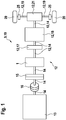
- a drive device 9 designed as a hybrid drive device 10 for a motor vehicle 11 is shown.
- the hybrid drive device 10 for the motor vehicle 11 comprises an internal combustion engine 13 and an electric motor 1 for driving the motor vehicle 11.
- the internal combustion engine 13 and the electric motor 1 are connected to one another by means of a drive shaft 14.
- the mechanical coupling between the engine 13 and the electric motor 1 can be made and canceled by means of a clutch 15.
- an elasticity 16 is arranged in the drive shaft 14, which couples the internal combustion engine 13 and the electric motor 1 together.
- the electric motor 1 is mechanically coupled to a differential gear 21.
- a converter 17 and a transmission 18 is arranged in the drive shaft 14, which connects the electric motor 1 and the differential gear 21 with each other.
- the drive wheels 20 are driven by side shafts 19.
- the two drive wheels 20 can each be braked or fixed with one parking brake 25, so that no rotation of the drive wheels 25 is possible even when the torque applied by the electric motor 1 is at standstill of the motor vehicle 11 and the actuated parking brakes 25. the drive wheels 25 are thus fixed. Notwithstanding this, only one parking brake 25 can be arranged on the drive shaft 14 between the transmission 18 and the differential gear 21 (not shown).
- Fig. 2 is a longitudinal section of the electric motor 1 is shown.
- the electric motor 1 has a rotor 2 and a stator 3 with electromagnets 4 as coils 4.
- the rotor 2 forms together with the drive shaft 14 a structural unit and on the rotor 2 permanent magnets 22 are arranged.
- Electromagnets 4 of the stator 3 are mounted on a housing 23 of the electric motor 1 and the housing 23 is mounted by means of a bearing 26 on the drive shaft 14.
- the electric motor 1 is also equipped with a sensor 27 designed as a digital sensor for detecting the angle of rotation of the rotor 2 or the drive shaft 14. By means of the sensor 27, the rotational angle ⁇ R of the rotor 2 is measured.
- Fig. 3 is a two-mass oscillator 5 shown.
- the dual-mass oscillator 5 is a rotational oscillator whose first mass 6 and second mass 7 execute a rotational movement fictitiously about an axis of rotation 24.
- the first mass 6 is connected to the second mass 7 by means of a torsion spring 8.
- the rotational moment of inertia J R of the first mass 6 corresponds to the rotational moment of inertia J R of the electric motor 1 or of the rotor 2 of the electric motor 1
- Fig. 1 shown components of the drive train 12, for example, the drive shaft 14, parts of the converter 17 and the transmission 18, parts of the differential gear 21, the side shaft 19 and the drive shaft 14 from a rotational movement.
- the rotational inertia of these components is known due to the structural design of the motor vehicle 11 and can be calculated.
- the motor vehicle 11 can perform a translational movement. In a translational movement of the motor vehicle 11, a moment of inertia occurs. This mass moment of inertia of the mass of the motor vehicle 11, which carries out a translational movement, is thereby converted into a replacement rotational moment of inertia J F of the motor vehicle 11.
- the replacement rotational moment of inertia J F of the second masses 7 in the dual mass oscillator 5 corresponds to the moment of inertia of the motor vehicle 11 with a translational motion converted inertia and the moment of inertia of the components of the drive train 12 with a rotational movement and the drive wheels 20.
- the drive train 12 in this model are Components of the drive device 9 between the electric motor 1 and the at least one parking brake 25, here two parking brakes 25, ie the drive shaft 14 of the electric motor 1 to the differential gear 21, the side shafts 19, the converter 17 and the transmission 18.
- the drive train 12th no device in which a slip occurs, for. B. a clutch 15 in which a slip between the two clutch discs is present.
- ⁇ R is the angle of rotation of the first mass 6 or of the rotor 2
- ⁇ ' R d ⁇ R / dt the angular velocity of the first mass 6
- ⁇ " R d ⁇ ' R / dt the angular acceleration of the first mass 6
- ⁇ F is the rotational angle of the second mass 7
- ⁇ ' F d ⁇ F / dt the angular velocity of the second mass 7
- ⁇ " F d ⁇ ' F / dt the angular acceleration of the second mass 7.
- the torsion bar 8 has the total stiffness c and the total damping d, which corresponds to the total stiffness c and the total damping d of the drive train 12 between the electric motor 1 and the two parking brakes 25.
- the motor vehicle 11 is at a standstill, so that the drive wheels 20 perform no rotational movement and with the two parking brakes 25, the drive wheels 20 are fixed.
- the electric motor 1 provides no torque M el , the rotor 2 is stationary and it is a first rotation angle ⁇ R1 , the rotor 2 detected.
- a torque M el is applied to the drive shaft 14 with the electric motor 1 and this torque M el causes a torsion of the drive train 12 and the torsion bar 8 because of the limited total stiffness c, since the total rigidity does not go to infinity ..
- the drive shaft 14 and the side shafts 19 are twisted.
- ⁇ F 0 because the drive wheels 20 are fixed and thus have not made a rotation angle.
- ⁇ R as is the difference between the second and first detected rotational angles ⁇ R , ie the rotational angle ⁇ R of the rotor 2 and the first mass 6 in the fixed drive wheels 20 up to the equilibrium state.
- the gear ratio is a known quantity and the total stiffness c of the drive train 12 is a mechanical characteristic that can either be calculated from the design data and / or determined by measurements.
- Equation (2) or (3) thus makes it possible to calculate the torque M em of the electric motor 1 independently of measured values for the voltage and the current at the electric motor 2 as well as parameters of a machine model for the electric motor 1.
- the calculated with the equation (2) or (3) torque M em of the electric motor 1 may, for. B. for a calibration of the parameters of a machine model, for a calibration of the current sensor of the electric motor 1 or for a determination of the total stiffness c of the drive train 12 are used, if the torque M em is known.
- the torque M em generated by the electric motor 1 can be determined in a simple manner without elaborate and error-prone machine models the electric motor 1 are required. It is only a brief stoppage of the motor vehicle 11 is required; It can thus be carried out, for example, with the motor vehicle 11 on a test stand or even at a short-term shutdown of the motor vehicle 11 at a traffic light in normal driving, if the parking brakes 25 are briefly actuated by the control of the motor vehicle 11 during standstill and while pressing the Parking brakes for a period of less than a second, z. B.
- the method can be used for all types of electric motors 1, z. GM, ASM, PSM or GRM.
Landscapes
- Engineering & Computer Science (AREA)
- Transportation (AREA)
- Mechanical Engineering (AREA)
- Power Engineering (AREA)
- General Physics & Mathematics (AREA)
- Physics & Mathematics (AREA)
- Combustion & Propulsion (AREA)
- Chemical & Material Sciences (AREA)
- Automation & Control Theory (AREA)
- Electric Propulsion And Braking For Vehicles (AREA)
- Force Measurement Appropriate To Specific Purposes (AREA)
- Testing Of Devices, Machine Parts, Or Other Structures Thereof (AREA)
- Hybrid Electric Vehicles (AREA)
Description
- Die vorliegende Erfindung betrifft ein Verfahren zur Bestimmung des Drehmomentes eines Elektromotors gemäß dem Oberbegriff des Anspruchs 1.
- Elektromotoren werden für verschiedene technische Anwendungen eingesetzt. Beispielsweise in Elektro- oder Hybridfahrzeugen werden Elektromotoren zum Antrieb eines Kraftfahrzeuges eingesetzt. Für den Einsatz von Elektromotoren in Kraftfahrzeugen ist eine ständige und genaue Erfassung des von dem Elektromotor erzeugten Drehmoments erforderlich, um ungewollte Beschleunigungen oder Verzögerungen des Kraftfahrzeuges vermeiden zu können. Hierzu wird das Drehmoment aus den gemessenen Phasenströmen der Elektromagnete des Elektromotors und dem Drehwinkel des Rotors des Elektromotors mit einem Maschinenmodell bestimmt. Das Maschinenmodell enthält betriebsabhängige Parameter wie z. B. die Temperatur des Stators und des Rotors oder den Rotorfluss, die aufwendig angepasst werden müssen. Fehler oder Ungenauigkeiten im Berechnungspfad des Maschinenmodells führen zu falsch ermittelten Drehmomenten, welche sicherheitsrelevante Folgen für das Kraftfahrzeug haben können. Aus diesem Grund gibt es Methoden, um das mit dem Maschinenmodell berechnete Drehmoment zu plausibilisieren aus Messwerten der Spannung und des Stromes, das somit in nachteiliger Weise von der Genauigkeit und Funktionsfähigkeit der Sensoren für diese Messwerte abhängt.
- Aus der
DE 41 22 391 A1 ist ein Verfahren zum Betrieb eines drehzahlregelbaren elektrischen Motors, insbesondere eines bürstenlosen Servomotors, bekannt. Durch Regelung der Motorgrößen Strom, Lagewinkel und Drehzahl wird die Drehzahl aus dem mittels eines Lagegebers gemessenen Lagewinkels durch einen Filter bestimmt. - Die Dokumente
DE 10 2008 026 509 A1 ,WO 2004/097359 A1 ,DE 10 2004 013 516 A1 undUS 5,754,967 offenbaren andere Methoden zur Bestimmung des Drehmoments an einem Kraftfahrzeug. - Erfindungsgemäßes Verfahren zur Bestimmung des Drehmomentes eines Elektromotors an einem Kraftfahrzeug, wobei von einem Rotor des Elektromotors ein Drehmoment erzeugt wird und das Drehmoment von einem Antriebsstrang auf wenigstens ein Antriebsrad übertragen wird mit den Schritten: Messen des Drehwinkels eines Rotors des Elektromotors, Bestimmen des von dem Rotor erzeugten Drehmomentes, wobei das wenigstens eine von dem Rotor angetriebene Antriebsrad festgesetzt wird, der feststehende Rotor kein Drehmoment erzeugt und ein erster Drehwinkel des feststehenden Rotors gemessen wird, anschließend von dem Rotor auf den Antriebsstrang ein Drehmoment aufgebracht wird, so dass der Rotor aufgrund der begrenzten Steifigkeit des Antriebsstranges eine Rotationsbewegung ausführt und anschließend in einem Gleichgewichtszustand zwischen dem von dem Rotor erzeugten Drehmoment und einem Gegendrehmoment des Antriebsstranges ein zweiter Drehwinkel des Rotors gemessen wird, aus den gemessenen Werte des ersten und zweiten Drehwinkels des Rotors das von dem Rotor erzeugte Drehmoment und/oder die Gesamtsteifigkeit des Antriebsstranges ermittelt werden. In vorteilhafter Weise kann damit das Drehmoment des Elektromotors bestimmt werden ohne dass Messwerte für den Strom oder die Spannung des Elektromotors erforderlich sind und somit keine Fehler aufgrund von einer mangelnden Genauigkeit oder Funktionsfähigkeit der Sensoren für die Messwerte auftreten.
In einer Variante werden das von dem Rotor erzeugte Drehmoment und/oder die Gesamtsteifigkeit des Antriebsstranges mit einem physikalischen Modell ermittelt. - In einer weiteren Ausführungsform ist das physikalische Modell ein Zweimassenschwinger mit einer ersten Masse mit einem Rotationsträgheitsmoment des Rotors des Elektromotors, einer zweiten Masse mit einem zweiten Ersatzrotationsträgheitsmoment und einer Drehstabfeder als Antriebsstrang zwischen der ersten Masse und der zweiten Masse.
- Zweckmäßig umfasst der Antriebsstrang ein Getriebe und/oder eine Antriebswelle und/oder ein Differentialgetriebe und/oder einen Wandler von denen das Drehmoment von dem Elektromotor zu dem wenigstens einen Antriebsrad übertragen wird.
- In einer weiteren Ausgestaltung wird für das physikalische Modell das Rotationsträgheitsmoment der ersten Masse und das Ersatzrotationsträgheitsmoment der zweiten Masse bestimmt.
- In einer ergänzenden Ausführungsform führt das wenigstens eine Antriebsrad, insbesondere sämtliche Antriebsräder, zwischen den Zeitpunkten des Messens des ersten und zweitens Drehwinkels des Rotors keine Rotationsbewegung aus.
- Zweckmäßig wird die Gesamtsteifigkeit der Drehstabfeder mit der Gesamtsteifigkeit des Antriebsstranges zwischen dem Elektromotor und der wenigstens einen Feststellbremse gleichgesetzt.
- In einer weiteren Variante umfasst das Ersatzrotationsträgheitsmoment der zweiten Masse neben dem Rotationsträgheitsmoment des wenigstens einen Antriebsrades zusätzlich das fiktive Rotationsträgheitsmoment des Kraftfahrzeuges, wobei das fiktive Rotationsträgheitsmoment des Kraftfahrzeuges aus dem translatorischen Trägheitsmoment des Kraftfahrzeuges berechnet wird.
- Insbesondere überträgt der Antriebsstrang bei der wenigstens eine geöffneten Feststellbremse das Drehmoment des Elektromotors von dem Elektromotor zu dem wenigstens einen Antriebsrad und der Antriebsstrang überträgt bei der wenigstens einen betätigten Feststellbremse das Drehmoment des Elektromotors von dem Elektromotor zu der wenigstens einen Feststellbremse.
- Vorzugsweise wird der zweite Winkel des Rotors bei einem im Wesentlichen feststehenden Rotor im Gleichgewichtszustand gemessen. Ein im Wesentlichen feststehender Rotor bedeutet, dass die Winkelgeschwindigkeit des Rotors kleiner als eine Umdrehung pro Minute ist.
In einer weiteren Ausführungsform werden das von dem Rotor erzeugte Drehmoment und/oder die Gesamtsteifigkeit des Antriebsstranges mit einer Gleichung ermittelt, wobei die Gleichung vorzugsweise lautet Mel = (c/u2)*(ϕR2 - ϕR1) und hierbei Mel das Drehmoment des Elektromotors (1) ist, c die Gesamtsteifigkeit des Antriebsstranges ist, u das Übersetzungsverhältnis des Getriebes ist, ϕR2 der zweite Drehwinkel des Rotors ist und ϕR1 der erste Drehwinkel des Rotors ist. - Im Nachfolgenden wird ein Ausführungsbeispiel der Erfindung unter Bezugnahme auf die beigefügten Zeichnungen näher beschrieben. Es zeigt:
- Fig. 1
- eine stark schematisierte Darstellung einer Antriebseinrichtung
- Fig. 2
- einen Längsschnitt eines Elektromotors,
- Fig. 3
- eine Ansicht eines Zweimassenschwingers und
- Fig. 4
- eine Seitenansicht eines Kraftfahrzeuges.
- In
Fig. 1 ist eine als Hybridantriebseinrichtung 10 ausgebildete Antriebseinrichtung 9 für ein Kraftfahrzeug 11 dargestellt. Die Hybridantriebseinrichtung 10 für das Kraftfahrzeug 11 umfasst einen Verbrennungsmotor 13 sowie einen Elektromotor 1 zum Antreiben des Kraftfahrzeuges 11. Der Verbrennungsmotor 13 und der Elektromotor 1 sind mittels einer Antriebswelle 14 miteinander verbunden. Die mechanische Koppelung zwischen dem Verbrennungsmotor 13 und dem Elektromotor 1 kann mittels einer Kupplung 15 hergestellt und aufgehoben werden. Ferner ist in der Antriebswelle 14, welche den Verbrennungsmotor 13 und den Elektromotor 1 miteinander koppelt, eine Elastizität 16 angeordnet. Der Elektromotor 1 ist mit einem Differentialgetriebe 21 mechanisch gekoppelt. In der Antriebswelle 14, welche den Elektromotor 1 und das Differentialgetriebe 21 miteinander verbindet, ist ein Wandler 17 und ein Getriebe 18 angeordnet. Mittels des Differentialgetriebes 21 werden durch Seitenwellen 19 die Antriebsräder 20 angetrieben. Die beiden Antriebsräder 20 können mit je einer Feststellbremse 25 gebremst bzw. festgesetzt werden, so dass bei einem Stillstand des Kraftfahrzeuges 11 und den betätigten Feststellbremsen 25 auch bei einem von dem Elektromotor 1 aufgebrachten Drehmoment keine (Rotations-)Bewegung der Antriebsräder 25 möglich ist, die Antriebsräder 25 somit feststehend sind. Abweichend hiervon kann auch nur eine Feststellbremse 25 an der Antriebswelle 14 zwischen dem Getriebe 18 und dem Differentialgetriebe 21 angeordnet sein (nicht dargestellt). - In
Fig. 2 ist ein Längsschnitt des Elektromotors 1 dargestellt. Der Elektromotor 1 weist einen Rotor 2 auf und einen Stator 3 mit Elektromagneten 4 als Spulen 4 auf. Der Rotor 2 bildet zusammen mit der Antriebswelle 14 eine Baueinheit und an dem Rotor 2 sind Permanentmagnete 22 angeordnet. Elektromagnete 4 des Stators 3 sind an einem Gehäuse 23 des Elektromotors 1 gelagert und das Gehäuse 23 ist mittels einer Lagerung 26 an der Antriebswelle 14 gelagert. Der Elektromotor 1 ist außerdem mit einem als Digitalsensor ausgebildeten Sensor 27 zur Erfassung des Drehwinkels des Rotors 2 bzw. der Antriebswelle 14 ausgestattet. Mittels des Sensors 27 wird der Drehwinkel ϕR des Rotors 2 gemessen. - In
Fig. 3 ist ein Zweimassenschwinger 5 abgebildet. Der Zweimassenschwinger 5 ist ein Rotationsschwinger dessen erste Masse 6 und zweite Masse 7 um eine Rotationsachse 24 eine Rotationsbewegung fiktiv ausführen. Die erste Masse 6 ist mit der zweiten Masse 7 mittels einer Drehstabfeder 8 verbunden. Das Rotationsträgheitsmoment JR der ersten Masse 6 entspricht dabei dem Rotationsträgheitsmoment JR des Elektromotors 1 bzw. des Rotors 2 des Elektromotors 1. In den inFig. 1 dargestellten Komponenten des Antriebsstranges 12 führen beispielsweise die Antriebswelle 14, Teile des Wandlers 17 und des Getriebes 18, Teile des Differentialgetriebes 21, die Seitenwelle 19 und die Antriebswelle 14 eine Rotationsbewegung aus. Das Rotationsträgheitsmoment dieser Komponenten ist aufgrund der konstruktiven Auslegung des Kraftfahrzeuges 11 bekannt und kann berechnet werden. Das Kraftfahrzeug 11 kann eine Translationsbewegung ausführen. Bei einer Translationsbewegung des Kraftfahrzeuges 11 tritt ein Massenträgheitsmoment auf. Dieses Massenträgheitsmoment der Masse des Kraftfahrzeuges 11, welche eine Translationsbewegung ausführt, wird dabei in ein Ersatzrotationsträgheitsmoment JF des Kraftfahrzeuges 11 umgerechnet. Das Ersatzrotationsträgheitsmoment JF der zweiten Massen 7 in dem Zweimassenschwinger 5 entspricht dabei dem aus dem Massenträgheitsmoment des Kraftfahrzeuges 11 mit einer Translationsbewegung umgerechneten Ersatzträgheitsmoment sowie dem Rotationsträgheitsmoment der Komponenten des Antriebsstranges 12 mit einer Rotationsbewegung und der Antriebsräder 20. Der Antriebsstrang 12 in diesem Modell sind die Komponenten der Antriebseinrichtung 9 zwischen dem Elektromotor 1 und der wenigstens einen Feststellbremse 25, hier zwei Feststellbremsen 25, d. h. die Antriebswelle 14 von dem Elektromotor 1 zu dem Differentialgetriebe 21, die Seitenwellen 19, der Wandler 17 und das Getriebe 18. Dabei weist der Antriebsstrang 12 keine Einrichtung auf, bei welcher ein Schlupf auftritt, z. B. eine Kupplung 15 bei welcher ein Schlupf zwischen beiden Kupplungsscheiben vorhanden ist. Das Getriebe 18 weist ein Übersetzungsverhältnis von z. B. u=10 auf, d. h. dass bei 10 Umdrehungen des Rotors 2 oder der Antriebswelle 14 zwischen dem Elektromotor 1 und dem Getriebe 18 führt die Antriebswelle 14 zwischen dem Getriebe 18 und dem Differentialgetriebe 21 eine Umdrehung aus. Weist der Antriebsstrang 12 kein Getriebe 18 auf ist u=1. - In diesem physikalischen Modell des Zweimassenschwingers 5 gelten die beiden Differentialgleichungen 1a und 1b


- Dabei ist ϕR der Drehwinkel der ersten Masse 6 bzw. des Rotors 2, (ϕ'R = dϕR/dt die Winkelgeschwindigkeit der ersten Masse 6 und ϕ"R = dϕ'R/dt die Winkelbeschleunigung der ersten Masse 6. In analoger Weise ist ϕF der Drehwinkel der zweiten Masse 7, ϕ'F = dϕF/dt die Winkelgeschwindigkeit der zweiten Masse 7 und ϕ"F = dϕ'F/dt die Winkelbeschleunigung der zweiten Masse 7. Die Drehstabfeder 8 weist die Gesamtsteifigkeit c und die Gesamtdämpfung d auf, welche der Gesamtsteifigkeit c und die Gesamtdämpfung d des Antriebsstranges 12 zwischen dem Elektromotor 1 und den beiden Feststellbremsen 25 entspricht.
- Das Kraftfahrzeug 11 befindet sich im Stillstand, so dass die Antriebsräder 20 keine Rotationsbewegung ausführen und mit den beiden Feststellbremsen 25 werden die Antriebsräder 20 festgesetzt. Der Elektromotor 1 erbringt kein Drehmoment Mel, der Rotor 2 ist feststehend und es wird ein erster Drehwinkel ϕR1, des Rotors 2 erfasst. Nach dem Festsetzen der beiden Antriebsräder 20 wird ein Drehmomentes Mel mit dem Elektromotor 1 auf die Antriebswelle 14 aufgebracht und dieses Drehmoment Mel bedingt eine Torsion des Antriebsstranges 12 bzw. der Drehstabfeder 8 wegen der begrenzten Gesamtsteifigkeit c, da die Gesamtsteifigkeit nicht gegen Unendlich geht.. Insbesondere die Antriebswelle 14 und die Seitenwellen 19 werden dabei tordiert. Der Antriebsstrang 12 bzw. die Drehstabfeder 8 bringen auf den Rotor 2 ein Gegendrehmoment ML bzw. ein Lastdrehmoment ML auf bis in einem Gleichgewichtszustand die Winkelgeschwindigkeit ϕ'R = dϕR/dt der ersten Masse 6 bzw. des Rotors 2 gleich Null ist. In diesem Gleichgewichtszustand wird ein zweiter Drehwinkel des Rotors 2 erfasst.
- Damit ist auch die Winkelbeschleunigung ϕ"R = dϕ'R/dt der ersten Masse 6 bzw. des Rotors 2 gleich Null und somit in der Differentialgleichung (1a) JR*ϕ"R = 0. Ferner ist neben der Winkelgeschwindigkeit ϕ'R = dϕR/dt der ersten Masse 6 bzw. des Rotors 2 auch die Winkelgeschwindigkeit der zweiten Masse 7 ϕ'F = dϕF/dt = 0, so dass in der Differentialgleichung (1a) auch d/u * (ϕ'R/u - ϕ'F) = 0 ist. Damit ergibt sich im Gleichgewichtszustand für Mem die folgende Gleichung (2):

- In dieser Gleichung ist ϕF = 0, weil die Antriebsräder 20 festgesetzt sind und damit keinen Drehwinkel ausgeführt haben. ϕR als ist die Differenz aus den zweiten und ersten erfassten Drehwinkel ϕR, d. h. der Drehwinkel ϕR des Rotor 2 bzw. der ersten Masse 6 bei den festgesetzten Antriebsrädern 20 bis zu dem Gleichgewichtszustand.
- Damit ergibt sich die Gleichung (3):

- Die Getriebeübersetzung ist eine bekannte Größe und die Gesamtsteifigkeit c des Antriebsstranges 12 ist eine mechanische Kenngröße, die entweder aus den Konstruktionsdaten berechnet und/oder mit Messungen bestimmt werden kann.
- Die Gleichung (2) bzw. (3) ermöglicht somit die Berechnung des Drehmomentes Mem des Elektromotors 1 unabhängig von Messwerten für die Spannung und den Strom an dem Elektromotor 2 sowie von Parametern eines Maschinenmodells für den Elektromotor 1.
- Das mit der Gleichung (2) bzw. (3) berechnete Drehmomentes Mem des Elektromotors 1 kann z. B. für eine Kalibrierung der Parameter eines Maschinenmodells, für eine Kalibrierung der Stromsensorik des Elektromotors 1 oder für eine Bestimmung der Gesamtsteifigkeit c des Antriebsstranges 12 eingesetzt werden, sofern das Drehmoment Mem bekannt ist.
- Insgesamt betrachtet sind mit dem erfindungsgemäßen Verfahren und der erfindungsgemäßen Antriebseinrichtung 9 wesentliche Vorteile verbunden. Das von dem Elektromotor 1 erzeugte Drehmoment Mem kann auf einfache Weise bestimmt werden ohne dass aufwendige und fehleranfällige Maschinenmodelle des Elektromotors 1 erforderlich sind. Es ist lediglich ein kurzzeitiger Stillstand des Kraftfahrzeuges 11 erforderlich; es kann somit beispielsweise mit dem Kraftfahrzeug 11 auf einem Prüfstand ausgeführt werden oder auch bei einem kurzzeitigen Stillstand des Kraftfahrzeuges 11 an einer Ampel im normalen Fahrbetrieb, sofern von der Steuerung des Kraftfahrzeuge 11 während des Stillstandes die Feststellbremsen 25 kurzzeitig betätigt werden und während des Betätigens der Feststellbremsen für einen Zeitraum von weniger als eine Sekunde, z. B. im Bereich von 300 bis 500 ms, von dem Elektromotor 1 das Drehmoment Mem erzeugt wird, kann somit die Differenz aus den zweiten und ersten erfassten Drehwinkel ϕR gemessen werden. Das Verfahren kann für alle Arten von Elektromotoren 1, z. B. GM, ASM, PSM oder GRM, eingesetzt werden.
Claims (9)
- Verfahren zur Bestimmung des Drehmomentes eines Elektromotors (1) an einem Kraftfahrzeug (11), wobei von einem Rotor (2) des Elektromotors (1) ein Drehmoment erzeugt wird und das Drehmoment von einem Antriebsstrang (12) auf wenigstens ein Antriebsrad (20) übertragen wird mit den Schritten:- Messen des Drehwinkels eines Rotors (2) des Elektromotors (1),- Bestimmen des von dem Rotor (2) erzeugten Drehmomentes,dadurch gekennzeichnet, dass- das wenigstens eine von dem Rotor (2) angetriebene Antriebsrad (20) festgesetzt wird, der feststehende Rotor (2) kein Drehmoment erzeugt und ein erster Drehwinkel des feststehenden Rotors (2) gemessen wird, anschließend- von dem Rotor (2) auf den Antriebsstrang (12) ein Drehmoment aufgebracht wird, so dass der Rotor (2) aufgrund der begrenzten Steifigkeit des Antriebsstranges (12) eine Rotationsbewegung ausführt und anschließend- in einem Gleichgewichtszustand zwischen dem von dem Rotor (2) erzeugten Drehmoment und einem Gegendrehmoment des Antriebsstranges (12) ein zweiter Drehwinkel des Rotors (2) gemessen wird,- aus den gemessenen Werten des ersten und zweiten Drehwinkels des Rotors (2) das von dem Rotor (2) erzeugte Drehmoment und/oder die Gesamtsteifigkeit des Antriebsstranges (12) ermittelt werden.
- Verfahren nach Anspruch 1,
dadurch gekennzeichnet, dass
das von dem Rotor (2) erzeugte Drehmoment und/oder die Gesamtsteifigkeit des Antriebsstranges (12) mit einem physikalischen Modell ermittelt werden. - Verfahren nach Anspruch 2,
dadurch gekennzeichnet, dass
das physikalische Modell ein Zweimassenschwinger (5) ist mit einer ersten Masse (6) mit einem Rotationsträgheitsmoment des Rotors (2) des Elektromotors (1), einer zweiten Masse (7) mit einem zweiten Ersatzrotationsträgheitsmoment und einer Drehstabfeder (8) als Antriebsstrang (12) zwischen der ersten Masse (6) und der zweiten Masse (7). - Verfahren nach einem oder mehreren der vorhergehenden Ansprüche,
dadurch gekennzeichnet, dass
der Antriebsstrang (12) ein Getriebe (18) und/oder eine Antriebswelle (14) und/oder ein Differentialgetriebe (21) und/oder einen Wandler (17) umfasst von denen ein Drehmoment von dem Elektromotor (1) zu dem wenigstens einen Antriebsrad (20) übertragen wird. - Verfahren nach einem oder mehreren der vorhergehenden Ansprüche,
dadurch gekennzeichnet, dass
das wenigstens eine Antriebsrad (20), insbesondere sämtliche Antriebsräder (20), zwischen den Zeitpunkten des Messens des ersten und zweitens Drehwinkels des Rotors (2) keine Rotationsbewegung ausführt. - Verfahren nach einem oder mehreren der Ansprüche 3 bis 5,
dadurch gekennzeichnet, dass
die Gesamtsteifigkeit der Drehstabfeder (8) mit der Gesamtsteifigkeit des Antriebsstranges (12) zwischen dem Elektromotor (1) und der wenigstens einen Feststellbremse (25) gleichgesetzt wird. - Verfahren nach einem oder mehreren der vorhergehenden Ansprüche,
dadurch gekennzeichnet, dass
der Antriebsstrang (12) bei der wenigstens einen geöffneten Feststellbremse (25) das Drehmoment des Elektromotors (1) von dem Elektromotor (1) zu dem wenigstens einen Antriebsrad (20) überträgt und der Antriebsstrang (12) bei der wenigstens einen betätigten Feststellbremse (25) das Drehmoment des Elektromotors (1) von dem Elektromotor (1) zu der wenigstens einen Feststellbremse (25) überträgt. - Verfahren nach einem oder mehreren der vorhergehenden Ansprüche,
dadurch gekennzeichnet, dass
der zweite Winkel des Rotors (2) bei einem im Wesentlichen feststehenden Rotor (2) im Gleichgewichtszustand gemessen wird. - Verfahren nach einem oder mehreren der vorhergehenden Ansprüche,
dadurch gekennzeichnet, dass
das von dem Rotor (2) erzeugte Drehmoment und/oder die Gesamtsteifigkeit des Antriebsstranges (12) mit einer Gleichung ermittelt werden, wobei die Gleichung vorzugsweise lautet Mel = (c/u2)*(ϕR2 - ϕR1) und hierbei Mel das Drehmoment des Elektromotors (1) ist, c die Gesamtsteifigkeit des Antriebsstranges (12) ist, u das Übersetzungsverhältnis des Getriebes(18) ist, ϕR2 der zweite Drehwinkel des Rotors (2) ist und ϕR1 der erste Drehwinkel des Rotors (2) ist.
Applications Claiming Priority (2)
| Application Number | Priority Date | Filing Date | Title |
|---|---|---|---|
| DE102010030365A DE102010030365A1 (de) | 2010-06-22 | 2010-06-22 | Verfahren zur Bestimmung des Drehmomentes eines Elektromotors |
| PCT/EP2011/057138 WO2011160880A1 (de) | 2010-06-22 | 2011-05-04 | Verfahren zur bestimmung des drehmomentes eines elektromotors |
Publications (2)
| Publication Number | Publication Date |
|---|---|
| EP2585803A1 EP2585803A1 (de) | 2013-05-01 |
| EP2585803B1 true EP2585803B1 (de) | 2018-03-28 |
Family
ID=44118981
Family Applications (1)
| Application Number | Title | Priority Date | Filing Date |
|---|---|---|---|
| EP11718075.2A Not-in-force EP2585803B1 (de) | 2010-06-22 | 2011-05-04 | Verfahren zur bestimmung des drehmomentes eines elektromotors |
Country Status (5)
| Country | Link |
|---|---|
| US (1) | US8857272B2 (de) |
| EP (1) | EP2585803B1 (de) |
| JP (1) | JP5546683B2 (de) |
| DE (1) | DE102010030365A1 (de) |
| WO (1) | WO2011160880A1 (de) |
Families Citing this family (7)
| Publication number | Priority date | Publication date | Assignee | Title |
|---|---|---|---|---|
| JP6536543B2 (ja) * | 2016-11-17 | 2019-07-03 | トヨタ自動車株式会社 | 車両用制御装置 |
| JP6465164B2 (ja) * | 2017-06-20 | 2019-02-06 | 株式会社明電舎 | 機械特性推定方法 |
| DE102017215252A1 (de) * | 2017-08-31 | 2019-02-28 | Volkswagen Aktiengesellschaft | Verfahren zur Bestimmung von mindestens einer Kenngröße einer elektrischen Maschine in einem Kraftfahrzeug |
| JP6900908B2 (ja) * | 2018-01-09 | 2021-07-07 | トヨタ自動車株式会社 | 車両用制御装置 |
| DE102018210004A1 (de) * | 2018-06-20 | 2019-12-24 | Robert Bosch Gmbh | Antriebsstrang für ein Fahrzeug |
| DE102020117262A1 (de) | 2020-07-01 | 2022-01-05 | Schaeffler Technologies AG & Co. KG | Vorrichtung zur Bestimmung eines Drehmoments in einem Antriebsstrang eines zumindest teilweise elektrisch betriebenen Kraftfahrzeugs |
| DE102023120837A1 (de) * | 2023-08-07 | 2025-02-13 | Bayerische Motoren Werke Aktiengesellschaft | Steuervorrichtung und verfahren zur überprüfung einer kalibrierung einer elektrischen maschine |
Family Cites Families (8)
| Publication number | Priority date | Publication date | Assignee | Title |
|---|---|---|---|---|
| DE4122391A1 (de) | 1991-07-05 | 1993-01-07 | Bosch Gmbh Robert | Verfahren zum betrieb eines drehzahlregelbaren motors |
| JP3207328B2 (ja) | 1994-12-16 | 2001-09-10 | 三菱電機株式会社 | 車両制御用軸トルク検出装置 |
| WO2004097359A1 (en) | 2003-04-28 | 2004-11-11 | Hansen Transmissions International Nv | Monitoring of load in a gear unit |
| DE102004013516A1 (de) | 2004-03-19 | 2005-10-06 | Continental Aktiengesellschaft | Verfahren zur Bestimmung eines Antriebsmomentes sowie ein System zur Durchführung des Verfahrens |
| DE102006027834B4 (de) * | 2006-06-16 | 2014-02-13 | Engineering Center Steyr Gmbh & Co. Kg | Verfahren zur Bestimmung eines Drehmoments |
| JP4978429B2 (ja) | 2007-11-01 | 2012-07-18 | アイシン・エィ・ダブリュ株式会社 | 電動機制御装置,電気自動車およびハイブリッド電気自動車 |
| DE102008026509B4 (de) * | 2008-05-21 | 2013-08-01 | Getrag Getriebe- Und Zahnradfabrik Hermann Hagenmeyer Gmbh & Cie Kg | Verfahren und Vorrichtung zur Verwendung in einer Steuerung eines Antriebsstrangs eines Kraftfahrzeuges |
| DE102009054603A1 (de) * | 2009-12-14 | 2011-06-16 | Robert Bosch Gmbh | Verfahren zur Steuerung eines Elektromotors |
-
2010
- 2010-06-22 DE DE102010030365A patent/DE102010030365A1/de not_active Withdrawn
-
2011
- 2011-05-04 JP JP2013515782A patent/JP5546683B2/ja not_active Expired - Fee Related
- 2011-05-04 EP EP11718075.2A patent/EP2585803B1/de not_active Not-in-force
- 2011-05-04 WO PCT/EP2011/057138 patent/WO2011160880A1/de not_active Ceased
- 2011-05-04 US US13/637,735 patent/US8857272B2/en not_active Expired - Fee Related
Also Published As
| Publication number | Publication date |
|---|---|
| JP2013539530A (ja) | 2013-10-24 |
| EP2585803A1 (de) | 2013-05-01 |
| JP5546683B2 (ja) | 2014-07-09 |
| DE102010030365A1 (de) | 2011-12-22 |
| WO2011160880A1 (de) | 2011-12-29 |
| US20130074609A1 (en) | 2013-03-28 |
| US8857272B2 (en) | 2014-10-14 |
Similar Documents
| Publication | Publication Date | Title |
|---|---|---|
| EP2585803B1 (de) | Verfahren zur bestimmung des drehmomentes eines elektromotors | |
| EP2264421B1 (de) | Prüfstandsanordnung | |
| DE19514093B4 (de) | Torsionsmoment-Meßeinrichtung, Schlupferkennungseinrichtung, Straßenreibungskoeffizient-Meßeinrichtung und Torsionsmomentmeßverfahren | |
| EP3853576B1 (de) | Verfahren zur ermittlung des getriebespieles eines getriebes | |
| DE2738325A1 (de) | Simulatoranordnung zur fahrzeugpruefung | |
| DE102012213709A1 (de) | Verfahren zum Erkennen eines Fehlerfalls einer Motoranordnung mit einer elektrischen Maschine und Motorsteuergerät | |
| WO2012103971A1 (de) | VERFAHREN UND VORRICHTUNG ZUR ÜBERWACHUNG DER BESTIMMUNGSGEMÄßEN FUNKTION MINDESTENS EINER ERSTEN UND EINER ZWEITEN KOMPONENTE EINES FAHRZEUGANTRIEBSSTRANGS | |
| EP2512859B1 (de) | Verfahren zur steuerung eines elektromotors | |
| EP3814651A1 (de) | Drehmomentübertragungsvorrichtung mit einem steuerungssystem zur ermittlung der drehrichtung des rotors | |
| EP3607294B1 (de) | Verfahren zum steuern, insbesondere regeln, eines antriebsstrangprüfstands mit realem getriebe | |
| AT413866B (de) | Verfahren zum starten einer brennkraftmaschine | |
| EP3994025B1 (de) | Verfahren und vorrichtung zum betreiben einer antriebsanordnung eines kraftfahrzeugs, antriebsanordnung | |
| DE102008041351A1 (de) | Hybridantriebssystem | |
| DE102013212177B4 (de) | Verfahren und System zum Bestimmen von Zustandsgrößen eines Elektromotors zum Antrieb eines Fahrzeugs | |
| DE102012002772A1 (de) | Elektromechanisches Lenksystem und Verfahren zum Betrieb eines elektromechanischen Lenksystems | |
| DE102004019379A1 (de) | Verfahren und Vorrichtung zum Ermitteln eines Differenzwinkels | |
| DE102008044303A1 (de) | Verfahren und Vorrichtung zum Betreiben eines Fahrzeuges | |
| EP3160785B1 (de) | Verfahren zum betreiben einer antriebseinrichtung eines kraftfahrzeugs sowie entsprechende antriebseinrichtung | |
| EP3837517B1 (de) | Aktorsystem, insbesondere für ein fahrzeug | |
| DE102015111409B3 (de) | Verfahren zur Bestimmung von Kräften und/oder Drehmomenten | |
| DE102015202229A1 (de) | Verfahren und Vorrichtung zur Drehmomentwelligkeitsbestimmung | |
| EP1338884B1 (de) | Rollenprüfstand für Kraftfahrzeug | |
| DE102013019483A1 (de) | Verfahren und Vorrichtung zur Schwingungsdämpfung einer angetriebenen Achse mit Momentenquerverteilung | |
| DE102024137706B3 (de) | Fahrzeug-Antriebsstrang mit einer Parksperre | |
| WO2016055039A2 (de) | Antriebssystem für ein schiff und verfahren zum betreiben des antriebssystems |
Legal Events
| Date | Code | Title | Description |
|---|---|---|---|
| PUAI | Public reference made under article 153(3) epc to a published international application that has entered the european phase |
Free format text: ORIGINAL CODE: 0009012 |
|
| 17P | Request for examination filed |
Effective date: 20130122 |
|
| AK | Designated contracting states |
Kind code of ref document: A1 Designated state(s): AL AT BE BG CH CY CZ DE DK EE ES FI FR GB GR HR HU IE IS IT LI LT LU LV MC MK MT NL NO PL PT RO RS SE SI SK SM TR |
|
| DAX | Request for extension of the european patent (deleted) | ||
| GRAP | Despatch of communication of intention to grant a patent |
Free format text: ORIGINAL CODE: EPIDOSNIGR1 |
|
| INTG | Intention to grant announced |
Effective date: 20171219 |
|
| GRAS | Grant fee paid |
Free format text: ORIGINAL CODE: EPIDOSNIGR3 |
|
| GRAA | (expected) grant |
Free format text: ORIGINAL CODE: 0009210 |
|
| AK | Designated contracting states |
Kind code of ref document: B1 Designated state(s): AL AT BE BG CH CY CZ DE DK EE ES FI FR GB GR HR HU IE IS IT LI LT LU LV MC MK MT NL NO PL PT RO RS SE SI SK SM TR |
|
| REG | Reference to a national code |
Ref country code: GB Ref legal event code: FG4D Free format text: NOT ENGLISH |
|
| REG | Reference to a national code |
Ref country code: CH Ref legal event code: EP |
|
| REG | Reference to a national code |
Ref country code: AT Ref legal event code: REF Ref document number: 983858 Country of ref document: AT Kind code of ref document: T Effective date: 20180415 |
|
| REG | Reference to a national code |
Ref country code: IE Ref legal event code: FG4D Free format text: LANGUAGE OF EP DOCUMENT: GERMAN |
|
| REG | Reference to a national code |
Ref country code: DE Ref legal event code: R096 Ref document number: 502011013958 Country of ref document: DE |
|
| REG | Reference to a national code |
Ref country code: FR Ref legal event code: PLFP Year of fee payment: 8 |
|
| PG25 | Lapsed in a contracting state [announced via postgrant information from national office to epo] |
Ref country code: FI Free format text: LAPSE BECAUSE OF FAILURE TO SUBMIT A TRANSLATION OF THE DESCRIPTION OR TO PAY THE FEE WITHIN THE PRESCRIBED TIME-LIMIT Effective date: 20180328 Ref country code: NO Free format text: LAPSE BECAUSE OF FAILURE TO SUBMIT A TRANSLATION OF THE DESCRIPTION OR TO PAY THE FEE WITHIN THE PRESCRIBED TIME-LIMIT Effective date: 20180628 Ref country code: LT Free format text: LAPSE BECAUSE OF FAILURE TO SUBMIT A TRANSLATION OF THE DESCRIPTION OR TO PAY THE FEE WITHIN THE PRESCRIBED TIME-LIMIT Effective date: 20180328 Ref country code: HR Free format text: LAPSE BECAUSE OF FAILURE TO SUBMIT A TRANSLATION OF THE DESCRIPTION OR TO PAY THE FEE WITHIN THE PRESCRIBED TIME-LIMIT Effective date: 20180328 |
|
| REG | Reference to a national code |
Ref country code: NL Ref legal event code: MP Effective date: 20180328 |
|
| REG | Reference to a national code |
Ref country code: LT Ref legal event code: MG4D |
|
| PG25 | Lapsed in a contracting state [announced via postgrant information from national office to epo] |
Ref country code: GR Free format text: LAPSE BECAUSE OF FAILURE TO SUBMIT A TRANSLATION OF THE DESCRIPTION OR TO PAY THE FEE WITHIN THE PRESCRIBED TIME-LIMIT Effective date: 20180629 Ref country code: RS Free format text: LAPSE BECAUSE OF FAILURE TO SUBMIT A TRANSLATION OF THE DESCRIPTION OR TO PAY THE FEE WITHIN THE PRESCRIBED TIME-LIMIT Effective date: 20180328 Ref country code: BG Free format text: LAPSE BECAUSE OF FAILURE TO SUBMIT A TRANSLATION OF THE DESCRIPTION OR TO PAY THE FEE WITHIN THE PRESCRIBED TIME-LIMIT Effective date: 20180628 Ref country code: SE Free format text: LAPSE BECAUSE OF FAILURE TO SUBMIT A TRANSLATION OF THE DESCRIPTION OR TO PAY THE FEE WITHIN THE PRESCRIBED TIME-LIMIT Effective date: 20180328 Ref country code: LV Free format text: LAPSE BECAUSE OF FAILURE TO SUBMIT A TRANSLATION OF THE DESCRIPTION OR TO PAY THE FEE WITHIN THE PRESCRIBED TIME-LIMIT Effective date: 20180328 |
|
| PG25 | Lapsed in a contracting state [announced via postgrant information from national office to epo] |
Ref country code: MT Free format text: LAPSE BECAUSE OF FAILURE TO SUBMIT A TRANSLATION OF THE DESCRIPTION OR TO PAY THE FEE WITHIN THE PRESCRIBED TIME-LIMIT Effective date: 20180328 |
|
| PG25 | Lapsed in a contracting state [announced via postgrant information from national office to epo] |
Ref country code: NL Free format text: LAPSE BECAUSE OF FAILURE TO SUBMIT A TRANSLATION OF THE DESCRIPTION OR TO PAY THE FEE WITHIN THE PRESCRIBED TIME-LIMIT Effective date: 20180328 Ref country code: EE Free format text: LAPSE BECAUSE OF FAILURE TO SUBMIT A TRANSLATION OF THE DESCRIPTION OR TO PAY THE FEE WITHIN THE PRESCRIBED TIME-LIMIT Effective date: 20180328 Ref country code: PL Free format text: LAPSE BECAUSE OF FAILURE TO SUBMIT A TRANSLATION OF THE DESCRIPTION OR TO PAY THE FEE WITHIN THE PRESCRIBED TIME-LIMIT Effective date: 20180328 Ref country code: ES Free format text: LAPSE BECAUSE OF FAILURE TO SUBMIT A TRANSLATION OF THE DESCRIPTION OR TO PAY THE FEE WITHIN THE PRESCRIBED TIME-LIMIT Effective date: 20180328 Ref country code: RO Free format text: LAPSE BECAUSE OF FAILURE TO SUBMIT A TRANSLATION OF THE DESCRIPTION OR TO PAY THE FEE WITHIN THE PRESCRIBED TIME-LIMIT Effective date: 20180328 Ref country code: AL Free format text: LAPSE BECAUSE OF FAILURE TO SUBMIT A TRANSLATION OF THE DESCRIPTION OR TO PAY THE FEE WITHIN THE PRESCRIBED TIME-LIMIT Effective date: 20180328 |
|
| PG25 | Lapsed in a contracting state [announced via postgrant information from national office to epo] |
Ref country code: SK Free format text: LAPSE BECAUSE OF FAILURE TO SUBMIT A TRANSLATION OF THE DESCRIPTION OR TO PAY THE FEE WITHIN THE PRESCRIBED TIME-LIMIT Effective date: 20180328 Ref country code: SM Free format text: LAPSE BECAUSE OF FAILURE TO SUBMIT A TRANSLATION OF THE DESCRIPTION OR TO PAY THE FEE WITHIN THE PRESCRIBED TIME-LIMIT Effective date: 20180328 Ref country code: CZ Free format text: LAPSE BECAUSE OF FAILURE TO SUBMIT A TRANSLATION OF THE DESCRIPTION OR TO PAY THE FEE WITHIN THE PRESCRIBED TIME-LIMIT Effective date: 20180328 |
|
| REG | Reference to a national code |
Ref country code: CH Ref legal event code: PL |
|
| PG25 | Lapsed in a contracting state [announced via postgrant information from national office to epo] |
Ref country code: PT Free format text: LAPSE BECAUSE OF FAILURE TO SUBMIT A TRANSLATION OF THE DESCRIPTION OR TO PAY THE FEE WITHIN THE PRESCRIBED TIME-LIMIT Effective date: 20180730 |
|
| REG | Reference to a national code |
Ref country code: DE Ref legal event code: R097 Ref document number: 502011013958 Country of ref document: DE |
|
| REG | Reference to a national code |
Ref country code: BE Ref legal event code: MM Effective date: 20180531 |
|
| PG25 | Lapsed in a contracting state [announced via postgrant information from national office to epo] |
Ref country code: MC Free format text: LAPSE BECAUSE OF FAILURE TO SUBMIT A TRANSLATION OF THE DESCRIPTION OR TO PAY THE FEE WITHIN THE PRESCRIBED TIME-LIMIT Effective date: 20180328 Ref country code: DK Free format text: LAPSE BECAUSE OF FAILURE TO SUBMIT A TRANSLATION OF THE DESCRIPTION OR TO PAY THE FEE WITHIN THE PRESCRIBED TIME-LIMIT Effective date: 20180328 |
|
| PLBE | No opposition filed within time limit |
Free format text: ORIGINAL CODE: 0009261 |
|
| STAA | Information on the status of an ep patent application or granted ep patent |
Free format text: STATUS: NO OPPOSITION FILED WITHIN TIME LIMIT |
|
| REG | Reference to a national code |
Ref country code: IE Ref legal event code: MM4A |
|
| GBPC | Gb: european patent ceased through non-payment of renewal fee |
Effective date: 20180628 |
|
| PG25 | Lapsed in a contracting state [announced via postgrant information from national office to epo] |
Ref country code: LI Free format text: LAPSE BECAUSE OF NON-PAYMENT OF DUE FEES Effective date: 20180531 Ref country code: CH Free format text: LAPSE BECAUSE OF NON-PAYMENT OF DUE FEES Effective date: 20180531 |
|
| 26N | No opposition filed |
Effective date: 20190103 |
|
| PG25 | Lapsed in a contracting state [announced via postgrant information from national office to epo] |
Ref country code: LU Free format text: LAPSE BECAUSE OF NON-PAYMENT OF DUE FEES Effective date: 20180504 |
|
| PG25 | Lapsed in a contracting state [announced via postgrant information from national office to epo] |
Ref country code: IE Free format text: LAPSE BECAUSE OF NON-PAYMENT OF DUE FEES Effective date: 20180504 Ref country code: GB Free format text: LAPSE BECAUSE OF NON-PAYMENT OF DUE FEES Effective date: 20180628 |
|
| PG25 | Lapsed in a contracting state [announced via postgrant information from national office to epo] |
Ref country code: SI Free format text: LAPSE BECAUSE OF FAILURE TO SUBMIT A TRANSLATION OF THE DESCRIPTION OR TO PAY THE FEE WITHIN THE PRESCRIBED TIME-LIMIT Effective date: 20180328 Ref country code: BE Free format text: LAPSE BECAUSE OF NON-PAYMENT OF DUE FEES Effective date: 20180531 |
|
| REG | Reference to a national code |
Ref country code: AT Ref legal event code: MM01 Ref document number: 983858 Country of ref document: AT Kind code of ref document: T Effective date: 20180504 |
|
| PG25 | Lapsed in a contracting state [announced via postgrant information from national office to epo] |
Ref country code: AT Free format text: LAPSE BECAUSE OF NON-PAYMENT OF DUE FEES Effective date: 20180504 |
|
| PGFP | Annual fee paid to national office [announced via postgrant information from national office to epo] |
Ref country code: DE Payment date: 20190716 Year of fee payment: 9 |
|
| PG25 | Lapsed in a contracting state [announced via postgrant information from national office to epo] |
Ref country code: TR Free format text: LAPSE BECAUSE OF FAILURE TO SUBMIT A TRANSLATION OF THE DESCRIPTION OR TO PAY THE FEE WITHIN THE PRESCRIBED TIME-LIMIT Effective date: 20180328 |
|
| PG25 | Lapsed in a contracting state [announced via postgrant information from national office to epo] |
Ref country code: HU Free format text: LAPSE BECAUSE OF FAILURE TO SUBMIT A TRANSLATION OF THE DESCRIPTION OR TO PAY THE FEE WITHIN THE PRESCRIBED TIME-LIMIT; INVALID AB INITIO Effective date: 20110504 |
|
| PG25 | Lapsed in a contracting state [announced via postgrant information from national office to epo] |
Ref country code: MK Free format text: LAPSE BECAUSE OF NON-PAYMENT OF DUE FEES Effective date: 20180328 Ref country code: CY Free format text: LAPSE BECAUSE OF FAILURE TO SUBMIT A TRANSLATION OF THE DESCRIPTION OR TO PAY THE FEE WITHIN THE PRESCRIBED TIME-LIMIT Effective date: 20180328 |
|
| PG25 | Lapsed in a contracting state [announced via postgrant information from national office to epo] |
Ref country code: IS Free format text: LAPSE BECAUSE OF FAILURE TO SUBMIT A TRANSLATION OF THE DESCRIPTION OR TO PAY THE FEE WITHIN THE PRESCRIBED TIME-LIMIT Effective date: 20180728 |
|
| PGFP | Annual fee paid to national office [announced via postgrant information from national office to epo] |
Ref country code: FR Payment date: 20200519 Year of fee payment: 10 |
|
| PGFP | Annual fee paid to national office [announced via postgrant information from national office to epo] |
Ref country code: IT Payment date: 20200528 Year of fee payment: 10 |
|
| REG | Reference to a national code |
Ref country code: DE Ref legal event code: R119 Ref document number: 502011013958 Country of ref document: DE |
|
| PG25 | Lapsed in a contracting state [announced via postgrant information from national office to epo] |
Ref country code: DE Free format text: LAPSE BECAUSE OF NON-PAYMENT OF DUE FEES Effective date: 20201201 |
|
| PG25 | Lapsed in a contracting state [announced via postgrant information from national office to epo] |
Ref country code: FR Free format text: LAPSE BECAUSE OF NON-PAYMENT OF DUE FEES Effective date: 20210531 |
|
| PG25 | Lapsed in a contracting state [announced via postgrant information from national office to epo] |
Ref country code: IT Free format text: LAPSE BECAUSE OF NON-PAYMENT OF DUE FEES Effective date: 20200504 |
|
| PG25 | Lapsed in a contracting state [announced via postgrant information from national office to epo] |
Ref country code: IT Free format text: LAPSE BECAUSE OF NON-PAYMENT OF DUE FEES Effective date: 20210504 |