EP2586105B1 - Steckverbinder - Google Patents
Steckverbinder Download PDFInfo
- Publication number
- EP2586105B1 EP2586105B1 EP11729901.6A EP11729901A EP2586105B1 EP 2586105 B1 EP2586105 B1 EP 2586105B1 EP 11729901 A EP11729901 A EP 11729901A EP 2586105 B1 EP2586105 B1 EP 2586105B1
- Authority
- EP
- European Patent Office
- Prior art keywords
- outer conductor
- conductor part
- ring
- plug
- housing
- Prior art date
- Legal status (The legal status is an assumption and is not a legal conclusion. Google has not performed a legal analysis and makes no representation as to the accuracy of the status listed.)
- Active
Links
Images

Classifications
-
- H—ELECTRICITY
- H01—ELECTRIC ELEMENTS
- H01R—ELECTRICALLY-CONDUCTIVE CONNECTIONS; STRUCTURAL ASSOCIATIONS OF A PLURALITY OF MUTUALLY-INSULATED ELECTRICAL CONNECTING ELEMENTS; COUPLING DEVICES; CURRENT COLLECTORS
- H01R13/00—Details of coupling devices of the kinds covered by groups H01R12/70 or H01R24/00 - H01R33/00
- H01R13/648—Protective earth or shield arrangements on coupling devices, e.g. anti-static shielding
- H01R13/6485—Electrostatic discharge protection
-
- H—ELECTRICITY
- H01—ELECTRIC ELEMENTS
- H01R—ELECTRICALLY-CONDUCTIVE CONNECTIONS; STRUCTURAL ASSOCIATIONS OF A PLURALITY OF MUTUALLY-INSULATED ELECTRICAL CONNECTING ELEMENTS; COUPLING DEVICES; CURRENT COLLECTORS
- H01R13/00—Details of coupling devices of the kinds covered by groups H01R12/70 or H01R24/00 - H01R33/00
- H01R13/62—Means for facilitating engagement or disengagement of coupling parts or for holding them in engagement
-
- H—ELECTRICITY
- H01—ELECTRIC ELEMENTS
- H01R—ELECTRICALLY-CONDUCTIVE CONNECTIONS; STRUCTURAL ASSOCIATIONS OF A PLURALITY OF MUTUALLY-INSULATED ELECTRICAL CONNECTING ELEMENTS; COUPLING DEVICES; CURRENT COLLECTORS
- H01R9/00—Structural associations of a plurality of mutually-insulated electrical connecting elements, e.g. terminal strips or terminal blocks; Terminals or binding posts mounted upon a base or in a case; Bases therefor
- H01R9/03—Connectors arranged to contact a plurality of the conductors of a multiconductor cable, e.g. tapping connections
- H01R9/05—Connectors arranged to contact a plurality of the conductors of a multiconductor cable, e.g. tapping connections for coaxial cables
-
- H—ELECTRICITY
- H01—ELECTRIC ELEMENTS
- H01R—ELECTRICALLY-CONDUCTIVE CONNECTIONS; STRUCTURAL ASSOCIATIONS OF A PLURALITY OF MUTUALLY-INSULATED ELECTRICAL CONNECTING ELEMENTS; COUPLING DEVICES; CURRENT COLLECTORS
- H01R13/00—Details of coupling devices of the kinds covered by groups H01R12/70 or H01R24/00 - H01R33/00
- H01R13/02—Contact members
- H01R13/15—Pins, blades or sockets having separate spring member for producing or increasing contact pressure
- H01R13/18—Pins, blades or sockets having separate spring member for producing or increasing contact pressure with the spring member surrounding the socket
-
- H—ELECTRICITY
- H01—ELECTRIC ELEMENTS
- H01R—ELECTRICALLY-CONDUCTIVE CONNECTIONS; STRUCTURAL ASSOCIATIONS OF A PLURALITY OF MUTUALLY-INSULATED ELECTRICAL CONNECTING ELEMENTS; COUPLING DEVICES; CURRENT COLLECTORS
- H01R13/00—Details of coupling devices of the kinds covered by groups H01R12/70 or H01R24/00 - H01R33/00
- H01R13/46—Bases; Cases
- H01R13/502—Bases; Cases composed of different pieces
-
- H—ELECTRICITY
- H01—ELECTRIC ELEMENTS
- H01R—ELECTRICALLY-CONDUCTIVE CONNECTIONS; STRUCTURAL ASSOCIATIONS OF A PLURALITY OF MUTUALLY-INSULATED ELECTRICAL CONNECTING ELEMENTS; COUPLING DEVICES; CURRENT COLLECTORS
- H01R13/00—Details of coupling devices of the kinds covered by groups H01R12/70 or H01R24/00 - H01R33/00
- H01R13/64—Means for preventing incorrect coupling
-
- H—ELECTRICITY
- H01—ELECTRIC ELEMENTS
- H01R—ELECTRICALLY-CONDUCTIVE CONNECTIONS; STRUCTURAL ASSOCIATIONS OF A PLURALITY OF MUTUALLY-INSULATED ELECTRICAL CONNECTING ELEMENTS; COUPLING DEVICES; CURRENT COLLECTORS
- H01R13/00—Details of coupling devices of the kinds covered by groups H01R12/70 or H01R24/00 - H01R33/00
- H01R13/648—Protective earth or shield arrangements on coupling devices, e.g. anti-static shielding
- H01R13/652—Protective earth or shield arrangements on coupling devices, e.g. anti-static shielding with earth pin, blade or socket
-
- H—ELECTRICITY
- H01—ELECTRIC ELEMENTS
- H01R—ELECTRICALLY-CONDUCTIVE CONNECTIONS; STRUCTURAL ASSOCIATIONS OF A PLURALITY OF MUTUALLY-INSULATED ELECTRICAL CONNECTING ELEMENTS; COUPLING DEVICES; CURRENT COLLECTORS
- H01R13/00—Details of coupling devices of the kinds covered by groups H01R12/70 or H01R24/00 - H01R33/00
- H01R13/648—Protective earth or shield arrangements on coupling devices, e.g. anti-static shielding
- H01R13/655—Protective earth or shield arrangements on coupling devices, e.g. anti-static shielding with earth brace
-
- H—ELECTRICITY
- H01—ELECTRIC ELEMENTS
- H01R—ELECTRICALLY-CONDUCTIVE CONNECTIONS; STRUCTURAL ASSOCIATIONS OF A PLURALITY OF MUTUALLY-INSULATED ELECTRICAL CONNECTING ELEMENTS; COUPLING DEVICES; CURRENT COLLECTORS
- H01R13/00—Details of coupling devices of the kinds covered by groups H01R12/70 or H01R24/00 - H01R33/00
- H01R13/648—Protective earth or shield arrangements on coupling devices, e.g. anti-static shielding
- H01R13/658—High frequency shielding arrangements, e.g. against EMI [Electro-Magnetic Interference] or EMP [Electro-Magnetic Pulse]
- H01R13/6581—Shield structure
- H01R13/6582—Shield structure with resilient means for engaging mating connector
- H01R13/6583—Shield structure with resilient means for engaging mating connector with separate conductive resilient members between mating shield members
-
- H—ELECTRICITY
- H01—ELECTRIC ELEMENTS
- H01R—ELECTRICALLY-CONDUCTIVE CONNECTIONS; STRUCTURAL ASSOCIATIONS OF A PLURALITY OF MUTUALLY-INSULATED ELECTRICAL CONNECTING ELEMENTS; COUPLING DEVICES; CURRENT COLLECTORS
- H01R13/00—Details of coupling devices of the kinds covered by groups H01R12/70 or H01R24/00 - H01R33/00
- H01R13/648—Protective earth or shield arrangements on coupling devices, e.g. anti-static shielding
- H01R13/658—High frequency shielding arrangements, e.g. against EMI [Electro-Magnetic Interference] or EMP [Electro-Magnetic Pulse]
- H01R13/6581—Shield structure
- H01R13/659—Shield structure with plural ports for distinct connectors
Definitions
- the present invention relates to a connector having an outer conductor part, which is designed for electrical and mechanical connection to an outer conductor of a cable and forms an electromagnetic shield of the connector, with an insulating part, which is designed to hold at least one inner conductor part at a predetermined position relative to the outer conductor part , according to the preamble of claim 1.
- the connector has an outer conductor part, an insulating part and an electrical contact.
- the outer conductor part is designed for electrical and mechanical connection to a coaxial cable and has ribs on its inner surface.
- An inner diameter of the outer conductor part is slightly larger than an outer diameter of the insulating part and four ribs rise radially inward from the inner surface of the outer conductor part. These four ribs form a press fit for the inner conductor part, so that rotation of the insulating part is prevented relative to the outer conductor part.
- a BNC Winket connector which has a housing for soldering onto a circuit board, in which an outer conductor part is arranged, known.
- an outer conductor part In the outer conductor part an insulating part is arranged, which holds an inner conductor.
- the outer conductor part has a circumferential groove formed at one end of the reduced diameter outer conductor part. Within this circumferential groove diametrically opposite elevations are formed.
- a C-shaped spring metal band with a pair of recesses is inserted into the circumferential groove so that the groove blocks axial movement of the spring metal band.
- the recesses of the Federmetallbandes take on the elevations of the outer conductor part to fix the Federmetallband in the circumferential groove and to provide an anti-rotation function within the circumferential groove.
- a rotation for the spring metal band is realized relative to the outer conductor part.
- an anti-rotation device for the outer conductor part is realized relative to the housing via an interaction of a flat surface on the outer conductor part and a corresponding flat surface within the housing.
- an electrical connector with an outer conductor part, an insulating part, which is arranged in an axial bore of the outer conductor part, and an inner conductor, which is arranged in an axial bore of the insulating part known. Furthermore, an anti-rotation device for the inner conductor relative to the insulating part and an anti-rotation for the insulating part is provided relative to the outer conductor part. On the inside of the outer conductor part elevations are arranged, which dig when inserting the insulating part in the softer material of the insulating part. There is no housing provided in which the outer conductor part and the insulating part would be arranged.
- the connector for a coaxial cable having an inner conductor, an outer conductor and a dielectric disposed therebetween known.
- the connector has a rear threaded nut Internal thread, which receives a rear end of an externally threaded.
- the connector housing has a recess for receiving an electrically conductive, compressible ring.
- the ring presses the outer conductor of the coaxial cable against a ramped wall portion of the threaded nut when the connector housing and the threaded nut are bolted together. This pressure function of the ring ensures an electrically conductive connection between the outer conductor of the coaxial cable and the ramp-shaped wall section by providing a constant contact force.
- the ring provides an anti-twist device for the coaxial cable relative to the connector housing and the threaded nut. An anti-rotation device for the insulating part of the connector is not provided.
- the invention has for its object to provide a connector of o.g. To improve type of assembly and functional safety.
- a housing in which the outer conductor part and the insulating part are arranged, wherein a rotation is provided, which is rotatably connected to the housing and engages through the outer conductor part into the insulating part such that the insulating part and the housing is rotatably connected to each other via the rotation
- a particularly reliable and easy to install anti-rotation is achieved in that the rotation is formed as a ring, in particular C-ring, which engages around the outer conductor part on its outer circumference and has a radially inwardly uplifting pin which passes through the outer conductor part in the Insulating part engages.
- a particularly reliable mechanical connection between the ring and the outer conductor part is achieved in that the pin engages through an opening in the outer side part, which is designed such that a rotational movement of the ring is blocked relative to the outer conductor part.
- a particularly reliable mechanical connection between the ring and the inner conductor part is achieved in that the pin engages in a recess in the insulating part, which is designed such that a rotational movement of the insulating part is blocked relative to the ring.
- a simple assembly and disassembly of the rotation on the housing obtained by the fact that the ring is formed of a resilient material.
- An additional axial securing of the ring relative to the housing is achieved in that on the outer circumference of the outer conductor part, a radially encircling groove is formed, in which the ring is arranged.
- An automatic installation of the anti-rotation with the mounting of the housing is achieved in that the anti-rotation is formed integrally with the housing.
- a connector for a cable with one or more inner conductors is achieved in a simple manner by providing at least one inner conductor part, which is designed for electrical and mechanical connection to an inner conductor of a cable, in particular an HF cable or a power cable.
- a connector in the Fig. 1 illustrated, preferred embodiment of a connector according to the invention comprises a housing 10, a radially disposed within the housing 10 outer conductor part 12 and a radially disposed within the outer conductor part insulating member 14.
- the housing 10, the outer conductor part 12 and the insulating member 14 are arranged coaxially to each other.
- the connector has a male end 16 for mating with a complementary connector (not shown), and a cable end 18 for electrically and mechanically connecting to a cable (not shown) having an outer conductor as the electromagnetic shield and at least one inner conductor.
- the outer conductor part 12 is designed for electrical and mechanical connection to the outer conductor (not shown) of the cable.
- the insulating part 14 is configured to receive at least one inner conductor part (not shown) such that the insulating part 14 holds the inner conductor part (s) at a predetermined position within the outer conductor part 12 and isolates it electrically with respect to the outer conductor part 12.
- the insulating part 14 is for example made of a made of dielectric material, wherein geometric dimensions and dielectric material are selected such that there is a predetermined impedance of the connector.
- the connector according to the invention can also be used for transmitting RF signals.
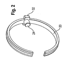
- an anti-rotation device 20 is arranged in the form of a C-ring, said C-ring 20 is aligned substantially parallel to a plane perpendicular to a longitudinal axis of the housing 10.
- the rotation lock 20 forms a circle segment or is a ring which is interrupted at one point.
- the rotation lock 20 is formed for example of a resilient material, so that the C-ring 20 can be bent radially inwardly or outwardly and then automatically returns under the action of a resilient force in its initial position. This allows mounting of the C-ring 20 on the outside of the outer conductor part 12 after its completion.
- the C-ring 20 for example, radially expanded and guided in the axial direction over the outer conductor part 12 until a predetermined point on the outer circumference of the outer conductor part 12 is reached, on which, for example, a groove 22 for receiving the C-ring 20 is formed. At this point, the C-ring 20 is relieved again, so that it comes to rest in its initial position in the groove 22 on the outer circumference of the outer conductor part 12.
- the anti-rotation device 20 is used for rotationally fixed fixing of the insulating part 14 within the housing 10 by means of a radially inwardly of the anti-rotation 20 rising pin 24, as described below with reference to Fig. 2 will be explained in more detail.
- Fig. 2 illustrates an anti-rotation 20 in the form of the C-ring with the pin 24.
- the C-ring 20 has a cuboidal thickening 32, which engages in a corresponding recess in an inner circumference of the housing 10. In this way, the C-ring 20 is rotatably connected to the housing 10 mechanically. How out Fig.
- the recess in the inner circumference of the housing 10 is formed as extending in the axial direction of groove 30 whose width is selected in the circumferential direction such that the cuboidal design of the C-ring 20 fits into it, however, a rotational movement of the C-ring 20 relative to the housing 10 by striking the cuboidal design of the C-ring 20 on inner walls of the groove 30 is prevented.
- the pin 24 engages through a through hole 26 in the outer conductor part 12 and into a groove 28 in the insulating member 14 so that the C-ring 20 is also rotatably connected to the insulating member 14.
- the insulating member 14 is rotatably connected to the housing 10, wherein the outer conductor part 12 has no function for this rotationally fixed connection between the housing 10 and insulating part 14.
- the outer conductor part 12 is no longer part of the tolerance chain for the rotation of the insulating part 14 in the housing 10th
- the rotation lock 20 ensures a predetermined orientation of the inner conductor parts held in the insulating part 14 relative to the housing 10. This ensures that when inserting the connector according to the invention in a complementary connector, the respective inner conductor portion of the connector according to the invention with a respective desired inner conductor portion of the complementary connector comes into electrical and mechanical contact.
- the arrangement of the inner conductor parts in the connector according to the invention corresponds to the arrangement of the inner conductor parts in the complementary connector.
Landscapes
- Details Of Connecting Devices For Male And Female Coupling (AREA)
- Coupling Device And Connection With Printed Circuit (AREA)
Description
- Die vorliegend Erfindung betrifft einen Steckverbinder mit einem Außenleiterteil, welches zum elektrischen und mechanischem Verbinden mit einem Außenleiter eines Kabels ausgebildet ist sowie eine elektromagnetische Abschirmung des Steckverbinders ausbildet, mit einem Isolierteil, welches zum Halten mindestens eines Innenleiterteil an einer vorbestimmten Position relativ zum Außenleiterteil ausgebildet ist, gemäß dem Oberbegriff des Anspruchs 1.
- Aus der
US 5 489 222 ist ein Miniatursteckverbinder mit einem Kontakt, welcher gegen Verdrehen gesichert ist, bekannt. Der Steckverbinder weist ein Außenleiterteil, ein Isolierteil und einen elektrischen Kontakt auf. Das Außenleiterteil ist zum elektrischen und mechanischen Verbinden mit einem Koaxialkabel ausgebildet und weist an dessen Innenfläche Rippen auf. Ein Innendurchmesser des Außenleiterteils ist etwas größer als ein Außendurchmesser des Isolierteils und vier Rippen erheben sich radial einwärts von der Innenfläche des Außenleiterteils. Diese vier Rippen bilden einen Presssitz für das Innenleiterteil aus, so dass eine Drehung des Isolierteils relativ zum Außenleiterteil verhindert ist. - Aus der
US 5 145 412 ist ein BNC-Winketsteckverbinder, welcher ein Gehäuses zum Auflöten auf eine Platine aufweist, in dem ein Außenleiterteil angeordnet ist, bekannt. In dem Außenleiterteil ist ein Isolierteil angeordnet, welches einen Innenleiter hält. Das Außenleiterteil weist eine Umfangsnut auf, die an einem Ende des Außenleiterteils mit reduziertem Durchmesser ausgebildet ist. Innerhalb dieser Umfangsnut sind diametral gegenüberliegende Erhebungen ausgebildet. Ein C-förmiges Federmetallband mit einem Paar von Ausnehmungen ist in die Umfangsnut eingesetzt, so dass die Nut eine axiale Bewegung des Federmetallbandes blockiert. Die Ausnehmungen des Federmetallbandes nehmen die Erhebungen des Außenleiterteils auf, um das Federmetallband in der Umfangsnut zu fixieren und eine Antirotationsfunktion innerhalb der Umfangsnut zur Verfügung zu stellen. Somit ist eine Verdrehsicherung für das Federmetallband relativ zum Außenleiterteil realisiert. Weiterhin ist über ein Zusammenwirken einer flachen Oberfläche auf dem Außenleiterteil und einer entsprechenden flachen Fläche innerhalb des Gehäuses eine Verdrehsicherung für das Außenleiterteil relativ zum Gehäuse realisiert. Es ist jedoch keine Verdrehsicherung für das Isolierteil vorgesehen. - Aus der
US 5 011 426 ist eine Steckverbinderanordnung mit einem Stecker mit einem Kunststoffgehäuse und einer Buchse bekannt. Das Kunststoffgehäuse weist Antirotationzapfen auf. Es ist jedoch kein Außenleiterteil vorgesehen, welches zum elektrischen und mechanischem Verbinden mit einem Außenleiter eines Kabels ausgebildet wäre. - Aus der
US 5 453 025 ist ein elektrischer Steckverbinder mit einem Außenleiterteil, einem Isolierteil, welches in einer Axialbohrung des Außenleiterteils angeordnet ist, und einem Innenleiter, welcher in einer Axialbohrung des Isolierteils angeordnet ist, bekannt. Weiterhin ist eine Verdrehsicherung für den Innenleiter relativ zum Isolierteil sowie eine Verdrehsicherung für das Isolierteil relativ zum Außenleiterteil vorgesehen. An der Innenseite des Außenleiterteils sind Erhebungen angeordnet, die sich beim Einschieben des Isolierteils in den weicheren Werkstoff des Isolierteils eingraben. Es ist kein Gehäuse vorgesehen, in dem das Außenleiterteil und das Isolierteil angeordnet wären. - Aus der
US 7 635 283 B1 ist ein Steckverbinder für ein Koaxialkabel, welches einen Innenleiter, einen Außenleiter und ein dazwischen angeordneten Dielektrikum aufweist, bekannt. Der Steckverbinder weist eine rückseitige Gewindemutter mit Innengewinde auf, welche ein rückwärtiges Ende eines mit Außengewinde aufnimmt. Das Steckverbindergehäuse weist eine Ausnehmung zur Aufnahme eines elektrisch leitenden, komprimierbaren Ringes auf. Der Ring drückt den Außenleiter des Koaxialkabels gegen einen rampenförmigen Wandabschnitt der Gewindemutter, wenn das Steckverbindergehäuse und die Gewindemutter miteinander verschraubt werden. Diese Andruckfunktion des Ringes stellt eine elektrisch leitende Verbindung zwischen dem Außenleiter des Koaxialkabels und dem rampenförmigen Wandabschnitt sicher, indem eine konstante Kontaktkraft zur Verfügung steht. Weiterhin stellt der Ring eine Verdrehsicherung für das Koaxialkabel relativ zum Steckverbindergehäuse und zur Gewindemutter zur Verfügung. Eine Verdrehsicherung für das Isolierteil des Steckverbinders ist nicht vorgesehen. - AUs der
US 2008/0160836 A1 ist ein Kabelsteckverbinder mit mehreren koaxial zueinander angeordneten Kontakten, zwischen denen jeweils ein Isolator angeordnet ist, bekannt. Zwei der Kontakte weisen an deren Innenseite, die einem der Isolatoren zugewandt ist, jeweils ein Antirotationselement auf, welches als Innenverzahnung oder Innengewinde ausgebildet ist. Diese Innenverzahnung drückt in die jeweiligen Isolatoren. So ist eine Drehbewegung von diesen zwei Kontakt relativ zu einem innersten Kontakt vermieden, wenn der Stecker in einen passenden Gegenstecker eingesteckt und gedreht wird. Das Antirotationselement ist an Innenseiten von Leiterteilen ausgebildet und greift daher nicht durch ein Außenleiterteil hindurch. Weiterhin ist kein Gehäuse vorgesehen, in dem die Kontakte und Isolatoren angeordnet wären. Weiterhin ist keiner der Kontakte derart ausgebildet, dass er eine elektromagnetische Abschirmung des Steckverbinders ausbilden könnte. - Der Erfindung liegt die Aufgabe zugrunde, einen Steckverbinder der o.g. Art hinsichtlich der Montage sowie Funktionssicherheit zu verbessern.
- Diese Aufgabe wird erfindungsgemäß durch einen Steckverbinder der o.g. Art mit den in Anspruch 1 gekennzeichneten Merkmalen gelöst. Vorteilhafte Ausgestaltungen der Erfindung sind in den weiteren Ansprüchen beschrieben.
- Bei einem Steckverbinder der o.g. Art ist es erfindungsgemäß vorgesehen, dass ein Gehäuse vorgesehen ist, in dem das Außenleiterteil und das Isolierteil angeordnet sind, wobei eine Verdrehsicherung vorgesehen ist, welche drehfest mit dem Gehäuse verbunden ist und durch das Außenleiterteil hindurch in das Isolierteil derart eingreift, dass das Isolierteil und das Gehäuse über die Verdrehsicherung drehfest miteinander verbunden ist
- Dies hat den Vorteil, dass hinsichtlich der Verdrehsicherung des Isolierteils innerhalb des Steckverbinders eine Toleranzkette verkürzt ist, da das Außenleiterteil für die Verdrehsicherung des Isolierteils überbrückt ist.
- Eine besonders funktionssichere und einfach zu montierende Verdrehsicherung erzielt man dadurch, dass die Verdrehsicherung als Ring, insbesondere C-Ring, ausgebildet ist, welcher das Außenleiterteil an seinem Außenumfang umgreift und einen sich radial nach innen erhebenden Stift aufweist, welcher durch das Außenleiterteil hindurch in das Isolierteil eingreift.
- Eine besonders funktionssichere mechanische Verbindung zwischen dem Ring und dem Außenleiterteil erzielt man dadurch, dass der Stift durch eine Durchbrechung im Außenteiterteil greift, welche derart ausgebildet ist, dass eine Drehbewegung des Ringes relativ zum Außenleiterteil blockiert ist.
- Eine besonders funktionssichere mechanische Verbindung zwischen dem Ring und dem Innenleiterteil erzielt man dadurch, dass der Stift in eine Ausnehmung im Isolierteil greift, welche derart ausgebildet ist, dass eine Drehbewegung des Isolierteil relativ zum Ring blockiert ist.
- Eine einfache Montage und Demontage der Verdrehsicherung am Gehäuse erzielt man dadurch, dass der Ring aus einem federelastischen Werkstoff ausgebildet ist.
- Eine zusätzlich axiale Sicherung des Ringes relativ zum Gehäuse erzielt man dadurch, dass an dem Außenumfang des Außenleiterteils eine radial umlaufende Nut ausgebildet ist, in der der Ring angeordnet ist.
- Eine automatische Montage der Verdrehsicherung mit der Montage des Gehäuses erzielt man dadurch, dass die Verdrehsicherung einstückig mit dem Gehäuse ausgebildet ist.
- Einen Steckverbinder für ein Kabel mit einem oder mehreren Innenleitern erzielt man auf einfache Weise dadurch, dass mindestens ein Innenleiterteil vorgesehen ist, welches zum elektrischen und mechanischen Verbinden mit einem Innenleiter eines Kabels, insbesondere eines HF-Kabels oder eines Stromkabels, ausgebildet ist.
- Die Erfindung wird im Folgenden anhand der Zeichnung näher erläutert. Diese zeigt in:
- Fig. 1
- eine bevorzugte Ausführungsform eines erfindungsgemäßen Steckverbinders in einem Längsschnitt und
- Fig. 2
- eine bevorzugte Ausführungsform einer Verdrehsicherung in Form eines C-Ringes in perspektivischer Ansicht.
- Die in
Fig. 1 dargestellte, bevorzugte Ausführungsform eines erfindungsgemäßen Steckverbinders umfasst ein Gehäuse 10, ein radial innerhalb des Gehäuses 10 angeordnetes Außenleiterteil 12 und ein radial innerhalb des Außenleiterteils angeordnetes Isolierteil 14. Das Gehäuse 10, das Außenleiterteil 12 und das Isolierteil 14 sind koaxial zueinander angeordnet. Der Steckverbinder weist ein steckseitiges Ende 16 zum steckenden Verbinden mit einem komplementären Steckverbinder (nicht dargestellt), und ein kabelseitiges Ende 18 zum elektrischen und mechanischen Verbinden mit einem Kabel (nicht dargestellt) mit einem Außenleiter als elektromagnetische Schirmung und mindestens einem Innenleiter auf. Das Außenleiterteil 12 ist zum elektrischen und mechanischen Verbinden mit dem Außenleiter (nicht dargestellt) des Kabels ausgebildet. Das Isolierteil 14 ist zur Aufnahme von mindestens einem Innenleiterteil (nicht dargestellt) derart ausgebildet, dass das Isolierteil 14 das bzw. die Innenleiterteile an einer vorbestimmten Position innerhalb des Außenleiterteils 12 hält und elektrisch bzgl. des Außenleiterteils 12 isoliert. Das Isolierteil 14 ist beispielsweise aus einem dielektrischen Werkstoff gefertigt, wobei geometrische Abmessungen und dielektrischer Werkstoff derart gewählt sind, dass sich eine vorbestimmte Impedanz des Steckverbinders ergibt. Hierdurch kann der erfindungsgemäße Steckverbinder auch zum Übertragen HF-Signalen verwendet werden. - Zwischen dem Gehäuse 10 und dem Außenleiterteil 12 ist eine Verdrehsicherung 20 in Form eines C-Ringes angeordnet, wobei dieser C-Ring 20 im Wesentlichen parallel zu einer Ebene senkrecht zu einer Längsachse des Gehäuses 10 ausgerichtet ist. Die Verdrehsicherung 20 bildet ein Kreissegment aus bzw. ist ein Ring, welcher an einer Stelle unterbrochen ist. Die Verdrehsicherung 20 ist beispielsweise aus einem federelastischen Werkstoff ausgebildet, so dass der C-Ring 20 radial nach innen bzw. außen gebogen werden kann und anschließend selbsttätig unter Wirkung einer federelastischen Kraft in seine Ausgangsstellung zurückkehrt. Dies ermöglicht eine Montage des C-Ringes 20 außen auf dem Außenleiterteil 12 nach dessen Fertigstellung. Hierzu wird der C-Ring 20 beispielsweise radial aufgeweitet und in axialer Richtung über das Außenleiterteil 12 geführt, bis eine vorbestimmte Stelle am Außenumfang des Außenleiterteils 12 erreicht ist, an der beispielsweise eine Nut 22 zur Aufnahme des C-Rings 20 ausgebildet ist. An dieser Stelle wird der C-Ring 20 wieder entlastet, so dass dieser in seine Ausgangstellung in der Nut 22 am Außenumfang des Außenleiterteils 12 zu liegen kommt. Die Verdrehsicherung 20 dient zum drehfesten fixieren des Isolierteils 14 innerhalb des Gehäuses 10 mittels eines sich radial nach innen von der Verdrehsicherung 20 erhebenden Stiftes 24, wie nachfolgend unter Bezugnahme auf
Fig. 2 noch näher erläutert wird. -
Fig. 2 veranschaulicht eine Verdrehsicherung 20 in Form des C-Ringes mit dem Stift 24. Im Bereich des Stiftes 24 weist der C-Ring 20 eine quaderförmige Verdickung 32 auf, welche in eine entsprechende Ausnehmung in einem Innenumfang des Gehäuses 10 greift. Auf diese Weise ist der C-Ring 20 drehfest mit dem Gehäuse 10 mechanisch verbunden. Wie ausFig. 1 ersichtlich, ist die Ausnehmung in dem Innenumfang des Gehäuses 10 als in axialer Richtung verlaufende Nut 30 ausgebildet, deren Breite in Umfangsrichtung derart gewählt ist, dass die quaderförmige Ausbildung des C-Ringes 20 zwar hinein passt, jedoch eine Drehbewegung des C-Ringes 20 relativ zum Gehäuse 10 durch Anschlagen der quaderförmige Ausbildung des C-Ringes 20 an Innenwandungen der Nut 30 verhindert ist. - Wie aus
Fig. 1 ersichtlich, greift der Stift 24 durch eine Durchgangsöffnung 26 im Außenleiterteil 12 und in eine Nut 28 im Isolierteil 14, so dass der C-Ring 20 auch drehfest mit dem Isolierteil 14 verbunden ist. Hierdurch ist das Isolierteil 14 drehfest mit dem Gehäuse 10 verbunden, wobei für diese drehfeste Verbindung zwischen Gehäuse 10 und Isolierteil 14 das Außenleiterteil 12 ohne Funktion ist. Mit anderen Worten ist das Außenleiterteil 12 nicht mehr Teil der Toleranzkette für die Verdrehsicherung des Isolierteils 14 in dem Gehäuse 10. - Die Verdrehsicherung 20 stellt eine vorbestimmte Orientierung der in dem Isolierteil 14 gehaltenen Innenleiterteile relativ zum Gehäuse 10 sicher. Hierdurch ist sichergestellt, dass bei einem Einstecken des erfindungsgemäßen Steckverbinders in einen komplementären Steckverbinder das jeweiligen Innenleiterteil des erfindungsgemäßen Steckverbinders mit einem jeweiligen gewünschten Innenleiterteil des komplementären Steckverbinders in elektrischen und mechanischen Kontakt kommt. Mit anderen Worten entspricht die Anordnung der Innenleiterteile in dem erfindungsgemäßen Steckverbinder der Anordnung der Innenleiterteile in dem komplementären Steckverbinder.
Claims (8)
- Steckverbinder mit einem Außenleiterteil (12), welches zum elektrischen und mechanischen Verbinden mit einem Außenleiter eines Kabels ausgebildet ist sowie eine elektromagnetische Abschirmung des Steckverbinders ausbildet, mit einem Isolierteil (14), welches zum Halten mindestens eines Innenleiterteils an einer vorbestimmten Position relativ zum Außenleiterteil (12) ausgebildet ist,
dadurch gekennzeichnet,
dass ein Gehäuse (10) vorgesehen ist, in dem das Außenleiterteil (12) und das Isolierteil (14) angeordnet sind, wobei eine Verdrehsicherung (20) vorgesehen ist, welche drehfest mit dem Gehäuse (10) verbunden ist und durch das Außenleiterteil (12) hindurch in das Isolierteil (14) derart eingreift, dass das Isolierteil (14) und das Gehäuse (10) über die Verdrehsicherung (20) drehfest miteinander verbunden sind. - Steckverbinder nach Anspruch 1, dadurch gekennzeichnet, dass die Verdrehsicherung (20) als Ring, insbesondere C-Ring, ausgebildet ist, welcher das Außenleiterteil (12) an seinem Außenumfang umgreift und einen sich radial nach innen erhebenden Stift (24) aufweist, welcher durch das Außenleiterteil (12) hindurch in das Isolierteil (14) eingreift.
- Steckverbinder nach Anspruch 2, dadurch gekennzeichnet, dass der Stift (24) durch eine Durchbrechung (24) im Außenleiterteil (12) greift, welche derart ausgebildet ist, dass eine Drehbewegung des Ringes (20) relativ zum Außenleiterteil (12) blockiert ist.
- Steckverbinder nach Anspruch 2 oder 3, dadurch gekennzeichnet, dass der Stift (24) in eine Ausnehmung (28) im Isolierteil (14) greift, welche derart ausgebildet ist, dass eine Drehbewegung des Isolierteil (14) relativ zum Ring (20) blockiert ist.
- Steckverbinder nach mindestens einem der Ansprüche 2 bis 4, dadurch gekennzeichnet, dass der Ring (20) aus einem federelastischen Werkstoff ausgebildet ist.
- Steckverbinder nach mindestens einem der Ansprüche 2 bis 5, dadurch gekennzeichnet, dass an dem Außenumfang des Außenleiterteils (12) eine radial umlaufende Nut (22) ausgebildet ist, in der der Ring (20) angeordnet ist.
- Steckverbinder nach mindestens einem der vorhergehenden Ansprüche, dadurch gekennzeichnet, dass die Verdrehsicherung (20) einstückig mit dem Gehäuse (10) ausgebildet ist.
- Steckverbinder nach mindestens einem der vorhergehenden Ansprüche, dadurch gekennzeichnet, dass mindestens ein Innenleiterteil vorgesehen ist, welches zum elektrischen und mechanischen Verbinden mit einem Innenleiter eines Kabels, insbesondere eines HF-Kabels oder eines Stromkabels, ausgebildet ist.
Applications Claiming Priority (2)
| Application Number | Priority Date | Filing Date | Title |
|---|---|---|---|
| DE202010009599U DE202010009599U1 (de) | 2010-06-28 | 2010-06-28 | Steckverbinder |
| PCT/EP2011/002728 WO2012000596A1 (de) | 2010-06-28 | 2011-06-01 | Steckverbinder |
Publications (2)
| Publication Number | Publication Date |
|---|---|
| EP2586105A1 EP2586105A1 (de) | 2013-05-01 |
| EP2586105B1 true EP2586105B1 (de) | 2014-04-02 |
Family
ID=42751413
Family Applications (1)
| Application Number | Title | Priority Date | Filing Date |
|---|---|---|---|
| EP11729901.6A Active EP2586105B1 (de) | 2010-06-28 | 2011-06-01 | Steckverbinder |
Country Status (10)
| Country | Link |
|---|---|
| US (1) | US8905787B2 (de) |
| EP (1) | EP2586105B1 (de) |
| JP (1) | JP2013539154A (de) |
| KR (1) | KR101767117B1 (de) |
| CN (1) | CN102959809B (de) |
| CA (1) | CA2800754C (de) |
| DE (1) | DE202010009599U1 (de) |
| TW (1) | TWM418456U (de) |
| WO (1) | WO2012000596A1 (de) |
| ZA (1) | ZA201208980B (de) |
Families Citing this family (5)
| Publication number | Priority date | Publication date | Assignee | Title |
|---|---|---|---|---|
| CN103594863B (zh) * | 2013-10-22 | 2015-11-18 | 资阳晨风电气有限公司 | 一种止退器 |
| CN104882751A (zh) * | 2015-06-02 | 2015-09-02 | 杨晓锋 | 高稳定性射频同轴连接器 |
| EP3767750B1 (de) * | 2019-07-16 | 2022-03-02 | Rosenberger Hochfrequenztechnik GmbH & Co. KG | Elektrischer steckverbinder, isolierschutzelement und verfahren zur montage eines elektrischen steckverbinders |
| CN112909660B (zh) * | 2021-01-20 | 2022-04-22 | 中航光电科技股份有限公司 | 一种连接器组件 |
| WO2023034396A1 (en) | 2021-09-01 | 2023-03-09 | Fci Usa Llc | High speed, ruggedized connector |
Family Cites Families (49)
| Publication number | Priority date | Publication date | Assignee | Title |
|---|---|---|---|---|
| US5011426A (en) | 1990-02-02 | 1991-04-30 | Molex Incorporated | Electrical connector assembly for vehicular suspension system component |
| US5145412A (en) | 1991-10-18 | 1992-09-08 | Foxconn International, Inc. | Filter connector |
| US5453025A (en) * | 1994-02-24 | 1995-09-26 | Redev Management Corp. | Electrical connector |
| US5489222A (en) * | 1994-09-09 | 1996-02-06 | The Whitaker Corporation | Mini connector with anti-rotational contact |
| JP3266750B2 (ja) * | 1994-09-16 | 2002-03-18 | 矢崎総業株式会社 | シールドコネクタの絶縁構造 |
| JP3032939B2 (ja) * | 1994-11-29 | 2000-04-17 | 矢崎総業株式会社 | シールドコネクタ |
| JP3585061B2 (ja) * | 1995-06-06 | 2004-11-04 | 矢崎総業株式会社 | シールドコネクタ |
| JP2978953B2 (ja) * | 1995-12-29 | 1999-11-15 | モレックス インコーポレーテッド | プラグ型電気コネクタとその製造方法 |
| US5928032A (en) * | 1997-01-31 | 1999-07-27 | Lucent Technologies, Inc. | Coaxial cable power adapter |
| JP3446989B2 (ja) * | 1997-05-29 | 2003-09-16 | 矢崎総業株式会社 | シールドコネクタ |
| JP3534290B2 (ja) * | 1997-08-07 | 2004-06-07 | 矢崎総業株式会社 | シールドコネクタ |
| JPH11102752A (ja) * | 1997-09-29 | 1999-04-13 | Yazaki Corp | シールドコネクタ |
| US5938465A (en) * | 1997-10-15 | 1999-08-17 | Palco Connector, Inc. | Machined dual spring ring connector for coaxial cable |
| JP3797585B2 (ja) * | 1998-08-11 | 2006-07-19 | 矢崎総業株式会社 | シールドコネクタ |
| FR2803696B1 (fr) * | 2000-01-06 | 2004-01-02 | Radiall Sa | Element de connecteur electrique coaxial realisant egalement une fonction de commutation |
| JP3604314B2 (ja) * | 2000-02-03 | 2004-12-22 | 松下電器産業株式会社 | Xsrケーブルコネクタ |
| JP2002042989A (ja) * | 2000-07-21 | 2002-02-08 | Sumitomo Wiring Syst Ltd | シールド端子 |
| FR2825195B1 (fr) * | 2001-05-22 | 2003-12-12 | Radiall Sa | Dispositif de connexion electrique coaxial coude |
| DE50100262D1 (de) * | 2001-05-29 | 2003-06-26 | Gerhard Petri Gmbh & Co Kg | Kabelverbindungsvorrichtung |
| TW540890U (en) * | 2001-08-24 | 2003-07-01 | Hon Hai Prec Ind Co Ltd | Cable connector assembly |
| US6929482B2 (en) * | 2003-01-27 | 2005-08-16 | Litton Systems, Inc. | Interconnection arrangement |
| JP2004327075A (ja) * | 2003-04-21 | 2004-11-18 | Sumitomo Wiring Syst Ltd | コネクタ |
| FR2857510B1 (fr) * | 2003-07-10 | 2005-10-07 | Arnould App Electr | Dispositif de connexion pour cable coaxial |
| JP2005108510A (ja) * | 2003-09-29 | 2005-04-21 | Clarion Co Ltd | 多極型高周波同軸コネクタ |
| US6932645B2 (en) * | 2003-12-31 | 2005-08-23 | Capativa Tech, Inc. | Structure of signal plug |
| US7198507B2 (en) * | 2005-02-09 | 2007-04-03 | Times Microwave Systems, Inc., division of Smiths Aerospace, Incorporated | Handgrip device for coaxial cable and coaxial cable assembly including handgrip device |
| TWM284120U (en) * | 2005-05-18 | 2005-12-21 | Time Technology Ind Co Ltd F | Improved structure of a coaxial connector |
| CN100550536C (zh) * | 2005-06-09 | 2009-10-14 | 株式会社自动网络技术研究所 | 同轴连接器和同轴连接器的连接器外壳的安装结构 |
| JP4753887B2 (ja) * | 2006-04-07 | 2011-08-24 | 株式会社オーディオテクニカ | マイクロホンのコネクタおよびそのシールド方法 |
| FR2901066A1 (fr) * | 2006-05-15 | 2007-11-16 | Radiall Sa | Connecteur coaxial |
| JP4965226B2 (ja) * | 2006-06-23 | 2012-07-04 | 株式会社オートネットワーク技術研究所 | 外導体端子 |
| DE202006011850U1 (de) * | 2006-08-02 | 2006-10-05 | Harting Electric Gmbh & Co. Kg | Kontaktelement für geschirmte Steckverbinder |
| JP4797892B2 (ja) * | 2006-09-07 | 2011-10-19 | 住友電装株式会社 | シールドコネクタ |
| CN101212108A (zh) * | 2006-12-29 | 2008-07-02 | 鸿富锦精密工业(深圳)有限公司 | 线缆连接器插头 |
| TWM327118U (en) * | 2007-05-22 | 2008-02-11 | Insert Entpr Co Ltd | Super-miniature coaxial micro switch connector |
| JP4445982B2 (ja) * | 2007-06-29 | 2010-04-07 | ホシデン株式会社 | コネクタ |
| KR100901409B1 (ko) * | 2007-07-06 | 2009-06-05 | 현대자동차주식회사 | 동축 케이블 커넥터 |
| US7425153B1 (en) * | 2007-09-25 | 2008-09-16 | D'addario & Company, Inc. | Electronic connector |
| EP2045884B1 (de) * | 2007-10-04 | 2010-12-01 | 3M Innovative Properties Company | Eine auf dem Gebiet der Telekommunikation an einen Verbinder anfügbare Abschirmung, eine Kombination des Verbinders und mindestens einer Abschirmung und Verfahren zum Abschirmen eines Verbinders |
| JP5186170B2 (ja) * | 2007-10-05 | 2013-04-17 | 矢崎総業株式会社 | 導電部材、その導電部材を有するコネクタ |
| US7503776B1 (en) * | 2007-12-07 | 2009-03-17 | Lear Corporation | Grounding connector for a shielded cable |
| US7695333B2 (en) * | 2007-12-13 | 2010-04-13 | Cooper Technologies Company | Single pole cable connector |
| US7645162B2 (en) * | 2008-01-24 | 2010-01-12 | Tyco Electronics Corporation | Connector assembly having a slider element |
| US7708591B2 (en) * | 2008-05-22 | 2010-05-04 | Yazaki Corporation | Shield connector |
| US7635283B1 (en) | 2008-11-24 | 2009-12-22 | Andrew Llc | Connector with retaining ring for coaxial cable and associated methods |
| US7909646B2 (en) * | 2009-08-10 | 2011-03-22 | 3M Innovative Properties Company | Electrical carrier assembly and system of electrical carrier assemblies |
| DE202010009597U1 (de) * | 2010-06-28 | 2010-09-09 | Rosenberger Hochfrequenztechnik Gmbh & Co. Kg | Steckverbinder mit einer radial wirkenden Rasteinrichtung |
| US8591255B2 (en) * | 2011-04-05 | 2013-11-26 | Ppc Broadband, Inc. | Locking and sealing connector |
| US8466378B1 (en) * | 2011-07-05 | 2013-06-18 | Arlington Industries, Inc. | Snap-in electrical cable connector with raised grounding lug |
-
2010
- 2010-06-28 DE DE202010009599U patent/DE202010009599U1/de not_active Expired - Lifetime
-
2011
- 2011-06-01 CN CN201180032106.4A patent/CN102959809B/zh active Active
- 2011-06-01 EP EP11729901.6A patent/EP2586105B1/de active Active
- 2011-06-01 KR KR1020127032445A patent/KR101767117B1/ko active Active
- 2011-06-01 WO PCT/EP2011/002728 patent/WO2012000596A1/de not_active Ceased
- 2011-06-01 US US13/807,173 patent/US8905787B2/en active Active
- 2011-06-01 JP JP2013517052A patent/JP2013539154A/ja not_active Withdrawn
- 2011-06-01 CA CA2800754A patent/CA2800754C/en not_active Expired - Fee Related
- 2011-06-21 TW TW100211196U patent/TWM418456U/zh not_active IP Right Cessation
-
2012
- 2012-11-28 ZA ZA2012/08980A patent/ZA201208980B/en unknown
Also Published As
| Publication number | Publication date |
|---|---|
| ZA201208980B (en) | 2013-07-31 |
| HK1182534A1 (en) | 2013-11-29 |
| CN102959809B (zh) | 2015-07-22 |
| KR101767117B1 (ko) | 2017-08-10 |
| CA2800754C (en) | 2018-01-30 |
| KR20130094727A (ko) | 2013-08-26 |
| DE202010009599U1 (de) | 2010-09-16 |
| US20130149885A1 (en) | 2013-06-13 |
| CN102959809A (zh) | 2013-03-06 |
| JP2013539154A (ja) | 2013-10-17 |
| CA2800754A1 (en) | 2012-01-05 |
| WO2012000596A1 (de) | 2012-01-05 |
| EP2586105A1 (de) | 2013-05-01 |
| US8905787B2 (en) | 2014-12-09 |
| TWM418456U (en) | 2011-12-11 |
Similar Documents
| Publication | Publication Date | Title |
|---|---|---|
| EP3420612B1 (de) | Elektrischer steckverbinder | |
| EP3103163B1 (de) | Koaxial-steckverbinderanordnung | |
| EP1747604B1 (de) | Gehäusekuppler für einen koaxialsteckverbinder | |
| EP2949013B1 (de) | Koaxialsteckverbindung mit einer mehrteiligen bajonettmutter | |
| EP3396791B1 (de) | Aussenleiteranordnung | |
| WO2012000588A1 (de) | Drehbarer steckverbinder | |
| EP2243198B1 (de) | Koaxialwinkelsteckverbinder | |
| WO2012000597A1 (de) | STECKVERBINDER MIT AUßENLEITERSCHIRM | |
| EP1573862B1 (de) | Elektrische anschlussverbindung, insbesondere für den anschluss eines aussenleiters eines koaxialkabels | |
| DE102016006598A1 (de) | Steckverbinder | |
| WO2006037488A1 (de) | Koaxialsteckverbinder mit schnellverschluss | |
| EP2754211A1 (de) | Kontaktgeschützter steckverbinder | |
| EP2586105B1 (de) | Steckverbinder | |
| EP3605746B1 (de) | Steckverbinder sowie steckverbindung mit einem solchen steckverbinder | |
| DE102008059308B4 (de) | Elektrische Trennwanddurchführung | |
| EP2973887B1 (de) | Steckverbinder | |
| DE102015106058B4 (de) | Steckverbindersystem | |
| EP2510593B1 (de) | Verbindungseinrichtung zum verbinden eines hochfrequenz-(hf)-kabels mit einem hf-interface | |
| EP1913661B1 (de) | Stecker mit haltefeder für einen erdungskontakt | |
| DE102017222809B4 (de) | Elektrischer Steckverbinder und Steckverbindung | |
| DE3638253A1 (de) | Kupplungsstueck mit einstellbarer laenge zur anwendung in einer hf-koaxialleitung | |
| EP1932220B1 (de) | Steckverbindung eines abschlussstecker für antennenanlagen | |
| EP2697869A1 (de) | Steckverbinder mit einem kontaktelement | |
| DE202017107625U1 (de) | Elektrischer Steckverbinder | |
| EP4070413B1 (de) | Steckverbindung zur übertragung elektrischer energie |
Legal Events
| Date | Code | Title | Description |
|---|---|---|---|
| PUAI | Public reference made under article 153(3) epc to a published international application that has entered the european phase |
Free format text: ORIGINAL CODE: 0009012 |
|
| 17P | Request for examination filed |
Effective date: 20121217 |
|
| AK | Designated contracting states |
Kind code of ref document: A1 Designated state(s): AL AT BE BG CH CY CZ DE DK EE ES FI FR GB GR HR HU IE IS IT LI LT LU LV MC MK MT NL NO PL PT RO RS SE SI SK SM TR |
|
| DAX | Request for extension of the european patent (deleted) | ||
| GRAP | Despatch of communication of intention to grant a patent |
Free format text: ORIGINAL CODE: EPIDOSNIGR1 |
|
| RIC1 | Information provided on ipc code assigned before grant |
Ipc: H01R 13/502 20060101ALI20131128BHEP Ipc: H01R 9/05 20060101ALI20131128BHEP Ipc: H01R 13/648 20060101AFI20131128BHEP Ipc: H01R 13/64 20060101ALI20131128BHEP |
|
| INTG | Intention to grant announced |
Effective date: 20131212 |
|
| GRAS | Grant fee paid |
Free format text: ORIGINAL CODE: EPIDOSNIGR3 |
|
| GRAA | (expected) grant |
Free format text: ORIGINAL CODE: 0009210 |
|
| AK | Designated contracting states |
Kind code of ref document: B1 Designated state(s): AL AT BE BG CH CY CZ DE DK EE ES FI FR GB GR HR HU IE IS IT LI LT LU LV MC MK MT NL NO PL PT RO RS SE SI SK SM TR |
|
| REG | Reference to a national code |
Ref country code: GB Ref legal event code: FG4D Free format text: NOT ENGLISH |
|
| REG | Reference to a national code |
Ref country code: AT Ref legal event code: REF Ref document number: 660632 Country of ref document: AT Kind code of ref document: T Effective date: 20140415 Ref country code: CH Ref legal event code: EP |
|
| REG | Reference to a national code |
Ref country code: IE Ref legal event code: FG4D Free format text: LANGUAGE OF EP DOCUMENT: GERMAN |
|
| REG | Reference to a national code |
Ref country code: DE Ref legal event code: R096 Ref document number: 502011002624 Country of ref document: DE Effective date: 20140522 |
|
| REG | Reference to a national code |
Ref country code: CH Ref legal event code: NV Representative=s name: GACHNANG AG PATENTANWAELTE, CH |
|
| REG | Reference to a national code |
Ref country code: SE Ref legal event code: TRGR |
|
| REG | Reference to a national code |
Ref country code: NL Ref legal event code: VDEP Effective date: 20140402 |
|
| REG | Reference to a national code |
Ref country code: LT Ref legal event code: MG4D |
|
| PG25 | Lapsed in a contracting state [announced via postgrant information from national office to epo] |
Ref country code: IS Free format text: LAPSE BECAUSE OF FAILURE TO SUBMIT A TRANSLATION OF THE DESCRIPTION OR TO PAY THE FEE WITHIN THE PRESCRIBED TIME-LIMIT Effective date: 20140802 Ref country code: CY Free format text: LAPSE BECAUSE OF FAILURE TO SUBMIT A TRANSLATION OF THE DESCRIPTION OR TO PAY THE FEE WITHIN THE PRESCRIBED TIME-LIMIT Effective date: 20140402 Ref country code: LT Free format text: LAPSE BECAUSE OF FAILURE TO SUBMIT A TRANSLATION OF THE DESCRIPTION OR TO PAY THE FEE WITHIN THE PRESCRIBED TIME-LIMIT Effective date: 20140402 Ref country code: NL Free format text: LAPSE BECAUSE OF FAILURE TO SUBMIT A TRANSLATION OF THE DESCRIPTION OR TO PAY THE FEE WITHIN THE PRESCRIBED TIME-LIMIT Effective date: 20140402 Ref country code: GR Free format text: LAPSE BECAUSE OF FAILURE TO SUBMIT A TRANSLATION OF THE DESCRIPTION OR TO PAY THE FEE WITHIN THE PRESCRIBED TIME-LIMIT Effective date: 20140703 Ref country code: CZ Free format text: LAPSE BECAUSE OF FAILURE TO SUBMIT A TRANSLATION OF THE DESCRIPTION OR TO PAY THE FEE WITHIN THE PRESCRIBED TIME-LIMIT Effective date: 20140402 Ref country code: BG Free format text: LAPSE BECAUSE OF FAILURE TO SUBMIT A TRANSLATION OF THE DESCRIPTION OR TO PAY THE FEE WITHIN THE PRESCRIBED TIME-LIMIT Effective date: 20140702 Ref country code: NO Free format text: LAPSE BECAUSE OF FAILURE TO SUBMIT A TRANSLATION OF THE DESCRIPTION OR TO PAY THE FEE WITHIN THE PRESCRIBED TIME-LIMIT Effective date: 20140702 |
|
| PG25 | Lapsed in a contracting state [announced via postgrant information from national office to epo] |
Ref country code: RS Free format text: LAPSE BECAUSE OF FAILURE TO SUBMIT A TRANSLATION OF THE DESCRIPTION OR TO PAY THE FEE WITHIN THE PRESCRIBED TIME-LIMIT Effective date: 20140402 Ref country code: ES Free format text: LAPSE BECAUSE OF FAILURE TO SUBMIT A TRANSLATION OF THE DESCRIPTION OR TO PAY THE FEE WITHIN THE PRESCRIBED TIME-LIMIT Effective date: 20140402 Ref country code: LV Free format text: LAPSE BECAUSE OF FAILURE TO SUBMIT A TRANSLATION OF THE DESCRIPTION OR TO PAY THE FEE WITHIN THE PRESCRIBED TIME-LIMIT Effective date: 20140402 Ref country code: HR Free format text: LAPSE BECAUSE OF FAILURE TO SUBMIT A TRANSLATION OF THE DESCRIPTION OR TO PAY THE FEE WITHIN THE PRESCRIBED TIME-LIMIT Effective date: 20140402 Ref country code: PL Free format text: LAPSE BECAUSE OF FAILURE TO SUBMIT A TRANSLATION OF THE DESCRIPTION OR TO PAY THE FEE WITHIN THE PRESCRIBED TIME-LIMIT Effective date: 20140402 |
|
| PG25 | Lapsed in a contracting state [announced via postgrant information from national office to epo] |
Ref country code: PT Free format text: LAPSE BECAUSE OF FAILURE TO SUBMIT A TRANSLATION OF THE DESCRIPTION OR TO PAY THE FEE WITHIN THE PRESCRIBED TIME-LIMIT Effective date: 20140804 |
|
| REG | Reference to a national code |
Ref country code: DE Ref legal event code: R097 Ref document number: 502011002624 Country of ref document: DE |
|
| PG25 | Lapsed in a contracting state [announced via postgrant information from national office to epo] |
Ref country code: EE Free format text: LAPSE BECAUSE OF FAILURE TO SUBMIT A TRANSLATION OF THE DESCRIPTION OR TO PAY THE FEE WITHIN THE PRESCRIBED TIME-LIMIT Effective date: 20140402 Ref country code: RO Free format text: LAPSE BECAUSE OF FAILURE TO SUBMIT A TRANSLATION OF THE DESCRIPTION OR TO PAY THE FEE WITHIN THE PRESCRIBED TIME-LIMIT Effective date: 20140402 Ref country code: MC Free format text: LAPSE BECAUSE OF FAILURE TO SUBMIT A TRANSLATION OF THE DESCRIPTION OR TO PAY THE FEE WITHIN THE PRESCRIBED TIME-LIMIT Effective date: 20140402 Ref country code: DK Free format text: LAPSE BECAUSE OF FAILURE TO SUBMIT A TRANSLATION OF THE DESCRIPTION OR TO PAY THE FEE WITHIN THE PRESCRIBED TIME-LIMIT Effective date: 20140402 Ref country code: SK Free format text: LAPSE BECAUSE OF FAILURE TO SUBMIT A TRANSLATION OF THE DESCRIPTION OR TO PAY THE FEE WITHIN THE PRESCRIBED TIME-LIMIT Effective date: 20140402 Ref country code: LU Free format text: LAPSE BECAUSE OF FAILURE TO SUBMIT A TRANSLATION OF THE DESCRIPTION OR TO PAY THE FEE WITHIN THE PRESCRIBED TIME-LIMIT Effective date: 20140601 |
|
| PLBE | No opposition filed within time limit |
Free format text: ORIGINAL CODE: 0009261 |
|
| STAA | Information on the status of an ep patent application or granted ep patent |
Free format text: STATUS: NO OPPOSITION FILED WITHIN TIME LIMIT |
|
| 26N | No opposition filed |
Effective date: 20150106 |
|
| REG | Reference to a national code |
Ref country code: IE Ref legal event code: MM4A |
|
| REG | Reference to a national code |
Ref country code: DE Ref legal event code: R097 Ref document number: 502011002624 Country of ref document: DE Effective date: 20150106 |
|
| PG25 | Lapsed in a contracting state [announced via postgrant information from national office to epo] |
Ref country code: IE Free format text: LAPSE BECAUSE OF NON-PAYMENT OF DUE FEES Effective date: 20140601 |
|
| PG25 | Lapsed in a contracting state [announced via postgrant information from national office to epo] |
Ref country code: RS Free format text: LAPSE BECAUSE OF FAILURE TO SUBMIT A TRANSLATION OF THE DESCRIPTION OR TO PAY THE FEE WITHIN THE PRESCRIBED TIME-LIMIT Effective date: 20141119 |
|
| PG25 | Lapsed in a contracting state [announced via postgrant information from national office to epo] |
Ref country code: SI Free format text: LAPSE BECAUSE OF FAILURE TO SUBMIT A TRANSLATION OF THE DESCRIPTION OR TO PAY THE FEE WITHIN THE PRESCRIBED TIME-LIMIT Effective date: 20140402 |
|
| PG25 | Lapsed in a contracting state [announced via postgrant information from national office to epo] |
Ref country code: MT Free format text: LAPSE BECAUSE OF FAILURE TO SUBMIT A TRANSLATION OF THE DESCRIPTION OR TO PAY THE FEE WITHIN THE PRESCRIBED TIME-LIMIT Effective date: 20140402 |
|
| PG25 | Lapsed in a contracting state [announced via postgrant information from national office to epo] |
Ref country code: SM Free format text: LAPSE BECAUSE OF FAILURE TO SUBMIT A TRANSLATION OF THE DESCRIPTION OR TO PAY THE FEE WITHIN THE PRESCRIBED TIME-LIMIT Effective date: 20140402 |
|
| REG | Reference to a national code |
Ref country code: FR Ref legal event code: PLFP Year of fee payment: 6 |
|
| PG25 | Lapsed in a contracting state [announced via postgrant information from national office to epo] |
Ref country code: HU Free format text: LAPSE BECAUSE OF FAILURE TO SUBMIT A TRANSLATION OF THE DESCRIPTION OR TO PAY THE FEE WITHIN THE PRESCRIBED TIME-LIMIT; INVALID AB INITIO Effective date: 20110601 Ref country code: TR Free format text: LAPSE BECAUSE OF FAILURE TO SUBMIT A TRANSLATION OF THE DESCRIPTION OR TO PAY THE FEE WITHIN THE PRESCRIBED TIME-LIMIT Effective date: 20140402 Ref country code: BE Free format text: LAPSE BECAUSE OF FAILURE TO SUBMIT A TRANSLATION OF THE DESCRIPTION OR TO PAY THE FEE WITHIN THE PRESCRIBED TIME-LIMIT Effective date: 20140630 |
|
| REG | Reference to a national code |
Ref country code: FR Ref legal event code: PLFP Year of fee payment: 7 |
|
| REG | Reference to a national code |
Ref country code: AT Ref legal event code: MM01 Ref document number: 660632 Country of ref document: AT Kind code of ref document: T Effective date: 20160601 |
|
| PG25 | Lapsed in a contracting state [announced via postgrant information from national office to epo] |
Ref country code: AT Free format text: LAPSE BECAUSE OF NON-PAYMENT OF DUE FEES Effective date: 20160601 |
|
| REG | Reference to a national code |
Ref country code: FR Ref legal event code: PLFP Year of fee payment: 8 |
|
| PG25 | Lapsed in a contracting state [announced via postgrant information from national office to epo] |
Ref country code: MK Free format text: LAPSE BECAUSE OF FAILURE TO SUBMIT A TRANSLATION OF THE DESCRIPTION OR TO PAY THE FEE WITHIN THE PRESCRIBED TIME-LIMIT Effective date: 20140402 |
|
| PGFP | Annual fee paid to national office [announced via postgrant information from national office to epo] |
Ref country code: FI Payment date: 20180627 Year of fee payment: 8 |
|
| PG25 | Lapsed in a contracting state [announced via postgrant information from national office to epo] |
Ref country code: AL Free format text: LAPSE BECAUSE OF FAILURE TO SUBMIT A TRANSLATION OF THE DESCRIPTION OR TO PAY THE FEE WITHIN THE PRESCRIBED TIME-LIMIT Effective date: 20140402 |
|
| PGFP | Annual fee paid to national office [announced via postgrant information from national office to epo] |
Ref country code: CH Payment date: 20180704 Year of fee payment: 8 |
|
| REG | Reference to a national code |
Ref country code: FI Ref legal event code: MAE |
|
| PG25 | Lapsed in a contracting state [announced via postgrant information from national office to epo] |
Ref country code: FI Free format text: LAPSE BECAUSE OF NON-PAYMENT OF DUE FEES Effective date: 20190601 |
|
| REG | Reference to a national code |
Ref country code: CH Ref legal event code: PL |
|
| PG25 | Lapsed in a contracting state [announced via postgrant information from national office to epo] |
Ref country code: CH Free format text: LAPSE BECAUSE OF NON-PAYMENT OF DUE FEES Effective date: 20190630 Ref country code: LI Free format text: LAPSE BECAUSE OF NON-PAYMENT OF DUE FEES Effective date: 20190630 |
|
| P01 | Opt-out of the competence of the unified patent court (upc) registered |
Effective date: 20230524 |
|
| REG | Reference to a national code |
Ref country code: DE Ref legal event code: R082 Ref document number: 502011002624 Country of ref document: DE Representative=s name: KANDLBINDER, MARKUS, DIPL.-PHYS., DE |
|
| PGFP | Annual fee paid to national office [announced via postgrant information from national office to epo] |
Ref country code: DE Payment date: 20250626 Year of fee payment: 15 |
|
| PGFP | Annual fee paid to national office [announced via postgrant information from national office to epo] |
Ref country code: GB Payment date: 20250617 Year of fee payment: 15 |
|
| PGFP | Annual fee paid to national office [announced via postgrant information from national office to epo] |
Ref country code: FR Payment date: 20250624 Year of fee payment: 15 |
|
| PGFP | Annual fee paid to national office [announced via postgrant information from national office to epo] |
Ref country code: SE Payment date: 20250619 Year of fee payment: 15 |
|
| PGFP | Annual fee paid to national office [announced via postgrant information from national office to epo] |
Ref country code: IT Payment date: 20250623 Year of fee payment: 15 |