EP2586476A2 - Vorrichtung zur Entnahme und zur Wiedereinspritzung von Fettgewebe, entsprechender Einspritzer und entsprechende Entnahmevorrichtungen - Google Patents
Vorrichtung zur Entnahme und zur Wiedereinspritzung von Fettgewebe, entsprechender Einspritzer und entsprechende Entnahmevorrichtungen Download PDFInfo
- Publication number
- EP2586476A2 EP2586476A2 EP12190658.0A EP12190658A EP2586476A2 EP 2586476 A2 EP2586476 A2 EP 2586476A2 EP 12190658 A EP12190658 A EP 12190658A EP 2586476 A2 EP2586476 A2 EP 2586476A2
- Authority
- EP
- European Patent Office
- Prior art keywords
- piston
- fluid
- receiving cavity
- proximal
- opening
- Prior art date
- Legal status (The legal status is an assumption and is not a legal conclusion. Google has not performed a legal analysis and makes no representation as to the accuracy of the status listed.)
- Withdrawn
Links
- 238000005070 sampling Methods 0.000 title claims abstract description 46
- 239000012530 fluid Substances 0.000 claims abstract description 81
- 238000011144 upstream manufacturing Methods 0.000 claims description 19
- 239000002537 cosmetic Substances 0.000 claims description 10
- 238000000034 method Methods 0.000 claims description 10
- 238000007789 sealing Methods 0.000 claims description 5
- 230000001225 therapeutic effect Effects 0.000 claims description 4
- 238000002560 therapeutic procedure Methods 0.000 claims description 2
- 230000003213 activating effect Effects 0.000 claims 1
- 230000000903 blocking effect Effects 0.000 claims 1
- 238000007599 discharging Methods 0.000 claims 1
- 210000001124 body fluid Anatomy 0.000 description 21
- 239000010839 body fluid Substances 0.000 description 21
- 210000000577 adipose tissue Anatomy 0.000 description 9
- 208000031968 Cadaver Diseases 0.000 description 8
- 238000006073 displacement reaction Methods 0.000 description 8
- 238000002347 injection Methods 0.000 description 7
- 239000007924 injection Substances 0.000 description 7
- 210000003491 skin Anatomy 0.000 description 7
- 230000000295 complement effect Effects 0.000 description 4
- 241001465754 Metazoa Species 0.000 description 3
- 238000004500 asepsis Methods 0.000 description 3
- 210000005075 mammary gland Anatomy 0.000 description 3
- 230000002093 peripheral effect Effects 0.000 description 3
- 238000000926 separation method Methods 0.000 description 3
- 239000013060 biological fluid Substances 0.000 description 2
- 239000008280 blood Substances 0.000 description 2
- 210000004369 blood Anatomy 0.000 description 2
- 239000010836 blood and blood product Substances 0.000 description 2
- 229940125691 blood product Drugs 0.000 description 2
- 238000005119 centrifugation Methods 0.000 description 2
- 238000011109 contamination Methods 0.000 description 2
- 210000004207 dermis Anatomy 0.000 description 2
- 230000000694 effects Effects 0.000 description 2
- 230000008030 elimination Effects 0.000 description 2
- 238000003379 elimination reaction Methods 0.000 description 2
- 239000001963 growth medium Substances 0.000 description 2
- 208000015181 infectious disease Diseases 0.000 description 2
- 238000003780 insertion Methods 0.000 description 2
- 230000037431 insertion Effects 0.000 description 2
- 238000007443 liposuction Methods 0.000 description 2
- 239000011241 protective layer Substances 0.000 description 2
- 102000008186 Collagen Human genes 0.000 description 1
- 108010035532 Collagen Proteins 0.000 description 1
- 206010020751 Hypersensitivity Diseases 0.000 description 1
- 239000002253 acid Substances 0.000 description 1
- 210000001217 buttock Anatomy 0.000 description 1
- 229920001436 collagen Polymers 0.000 description 1
- 230000008878 coupling Effects 0.000 description 1
- 238000010168 coupling process Methods 0.000 description 1
- 238000005859 coupling reaction Methods 0.000 description 1
- 230000009977 dual effect Effects 0.000 description 1
- 230000002500 effect on skin Effects 0.000 description 1
- 239000000284 extract Substances 0.000 description 1
- 239000004744 fabric Substances 0.000 description 1
- 239000011521 glass Substances 0.000 description 1
- 239000000463 material Substances 0.000 description 1
- 230000000813 microbial effect Effects 0.000 description 1
- 229930014626 natural product Natural products 0.000 description 1
- 238000005191 phase separation Methods 0.000 description 1
- 239000000047 product Substances 0.000 description 1
- 230000001681 protective effect Effects 0.000 description 1
- 230000002787 reinforcement Effects 0.000 description 1
- 238000009958 sewing Methods 0.000 description 1
- 210000004003 subcutaneous fat Anatomy 0.000 description 1
- 239000006228 supernatant Substances 0.000 description 1
- 210000001519 tissue Anatomy 0.000 description 1
- 239000012780 transparent material Substances 0.000 description 1
- 230000037303 wrinkles Effects 0.000 description 1
Images


Classifications
-
- A—HUMAN NECESSITIES
- A61—MEDICAL OR VETERINARY SCIENCE; HYGIENE
- A61M—DEVICES FOR INTRODUCING MEDIA INTO, OR ONTO, THE BODY; DEVICES FOR TRANSDUCING BODY MEDIA OR FOR TAKING MEDIA FROM THE BODY; DEVICES FOR PRODUCING OR ENDING SLEEP OR STUPOR
- A61M5/00—Devices for bringing media into the body in a subcutaneous, intra-vascular or intramuscular way; Accessories therefor, e.g. filling or cleaning devices, arm-rests
- A61M5/178—Syringes
- A61M5/31—Details
- A61M5/315—Pistons; Piston-rods; Guiding, blocking or restricting the movement of the rod or piston; Appliances on the rod for facilitating dosing ; Dosing mechanisms
- A61M5/31511—Piston or piston-rod constructions, e.g. connection of piston with piston-rod
-
- A—HUMAN NECESSITIES
- A61—MEDICAL OR VETERINARY SCIENCE; HYGIENE
- A61M—DEVICES FOR INTRODUCING MEDIA INTO, OR ONTO, THE BODY; DEVICES FOR TRANSDUCING BODY MEDIA OR FOR TAKING MEDIA FROM THE BODY; DEVICES FOR PRODUCING OR ENDING SLEEP OR STUPOR
- A61M1/00—Suction or pumping devices for medical purposes; Devices for carrying-off, for treatment of, or for carrying-over, body-liquids; Drainage systems
- A61M1/64—Containers with integrated suction means
- A61M1/67—Containers incorporating a piston-type member to create suction, e.g. syringes
-
- A—HUMAN NECESSITIES
- A61—MEDICAL OR VETERINARY SCIENCE; HYGIENE
- A61M—DEVICES FOR INTRODUCING MEDIA INTO, OR ONTO, THE BODY; DEVICES FOR TRANSDUCING BODY MEDIA OR FOR TAKING MEDIA FROM THE BODY; DEVICES FOR PRODUCING OR ENDING SLEEP OR STUPOR
- A61M1/00—Suction or pumping devices for medical purposes; Devices for carrying-off, for treatment of, or for carrying-over, body-liquids; Drainage systems
- A61M1/80—Suction pumps
- A61M1/81—Piston pumps, e.g. syringes
- A61M1/815—Piston pumps, e.g. syringes the barrel serving as aspiration container, e.g. in a breast pump
-
- A—HUMAN NECESSITIES
- A61—MEDICAL OR VETERINARY SCIENCE; HYGIENE
- A61M—DEVICES FOR INTRODUCING MEDIA INTO, OR ONTO, THE BODY; DEVICES FOR TRANSDUCING BODY MEDIA OR FOR TAKING MEDIA FROM THE BODY; DEVICES FOR PRODUCING OR ENDING SLEEP OR STUPOR
- A61M1/00—Suction or pumping devices for medical purposes; Devices for carrying-off, for treatment of, or for carrying-over, body-liquids; Drainage systems
- A61M1/89—Suction aspects of liposuction
- A61M1/895—Suction aspects of liposuction with means for reinjection of collected fat
-
- A—HUMAN NECESSITIES
- A61—MEDICAL OR VETERINARY SCIENCE; HYGIENE
- A61M—DEVICES FOR INTRODUCING MEDIA INTO, OR ONTO, THE BODY; DEVICES FOR TRANSDUCING BODY MEDIA OR FOR TAKING MEDIA FROM THE BODY; DEVICES FOR PRODUCING OR ENDING SLEEP OR STUPOR
- A61M5/00—Devices for bringing media into the body in a subcutaneous, intra-vascular or intramuscular way; Accessories therefor, e.g. filling or cleaning devices, arm-rests
- A61M5/14—Infusion devices, e.g. infusing by gravity; Blood infusion; Accessories therefor
- A61M5/142—Pressure infusion, e.g. using pumps
- A61M5/145—Pressure infusion, e.g. using pumps using pressurised reservoirs, e.g. pressurised by means of pistons
- A61M5/1452—Pressure infusion, e.g. using pumps using pressurised reservoirs, e.g. pressurised by means of pistons pressurised by means of pistons
- A61M5/14546—Front-loading type injectors
-
- A—HUMAN NECESSITIES
- A61—MEDICAL OR VETERINARY SCIENCE; HYGIENE
- A61M—DEVICES FOR INTRODUCING MEDIA INTO, OR ONTO, THE BODY; DEVICES FOR TRANSDUCING BODY MEDIA OR FOR TAKING MEDIA FROM THE BODY; DEVICES FOR PRODUCING OR ENDING SLEEP OR STUPOR
- A61M5/00—Devices for bringing media into the body in a subcutaneous, intra-vascular or intramuscular way; Accessories therefor, e.g. filling or cleaning devices, arm-rests
- A61M5/14—Infusion devices, e.g. infusing by gravity; Blood infusion; Accessories therefor
- A61M5/142—Pressure infusion, e.g. using pumps
- A61M5/145—Pressure infusion, e.g. using pumps using pressurised reservoirs, e.g. pressurised by means of pistons
- A61M5/1452—Pressure infusion, e.g. using pumps using pressurised reservoirs, e.g. pressurised by means of pistons pressurised by means of pistons
- A61M5/14566—Pressure infusion, e.g. using pumps using pressurised reservoirs, e.g. pressurised by means of pistons pressurised by means of pistons with a replaceable reservoir for receiving a piston rod of the pump
-
- A—HUMAN NECESSITIES
- A61—MEDICAL OR VETERINARY SCIENCE; HYGIENE
- A61M—DEVICES FOR INTRODUCING MEDIA INTO, OR ONTO, THE BODY; DEVICES FOR TRANSDUCING BODY MEDIA OR FOR TAKING MEDIA FROM THE BODY; DEVICES FOR PRODUCING OR ENDING SLEEP OR STUPOR
- A61M5/00—Devices for bringing media into the body in a subcutaneous, intra-vascular or intramuscular way; Accessories therefor, e.g. filling or cleaning devices, arm-rests
- A61M5/14—Infusion devices, e.g. infusing by gravity; Blood infusion; Accessories therefor
- A61M5/168—Means for controlling media flow to the body or for metering media to the body, e.g. drip meters, counters ; Monitoring media flow to the body
- A61M5/16804—Flow controllers
-
- A—HUMAN NECESSITIES
- A61—MEDICAL OR VETERINARY SCIENCE; HYGIENE
- A61M—DEVICES FOR INTRODUCING MEDIA INTO, OR ONTO, THE BODY; DEVICES FOR TRANSDUCING BODY MEDIA OR FOR TAKING MEDIA FROM THE BODY; DEVICES FOR PRODUCING OR ENDING SLEEP OR STUPOR
- A61M5/00—Devices for bringing media into the body in a subcutaneous, intra-vascular or intramuscular way; Accessories therefor, e.g. filling or cleaning devices, arm-rests
- A61M5/14—Infusion devices, e.g. infusing by gravity; Blood infusion; Accessories therefor
- A61M5/168—Means for controlling media flow to the body or for metering media to the body, e.g. drip meters, counters ; Monitoring media flow to the body
- A61M5/16877—Adjusting flow; Devices for setting a flow rate
-
- A—HUMAN NECESSITIES
- A61—MEDICAL OR VETERINARY SCIENCE; HYGIENE
- A61M—DEVICES FOR INTRODUCING MEDIA INTO, OR ONTO, THE BODY; DEVICES FOR TRANSDUCING BODY MEDIA OR FOR TAKING MEDIA FROM THE BODY; DEVICES FOR PRODUCING OR ENDING SLEEP OR STUPOR
- A61M1/00—Suction or pumping devices for medical purposes; Devices for carrying-off, for treatment of, or for carrying-over, body-liquids; Drainage systems
- A61M1/71—Suction drainage systems
- A61M1/77—Suction-irrigation systems
-
- A—HUMAN NECESSITIES
- A61—MEDICAL OR VETERINARY SCIENCE; HYGIENE
- A61M—DEVICES FOR INTRODUCING MEDIA INTO, OR ONTO, THE BODY; DEVICES FOR TRANSDUCING BODY MEDIA OR FOR TAKING MEDIA FROM THE BODY; DEVICES FOR PRODUCING OR ENDING SLEEP OR STUPOR
- A61M5/00—Devices for bringing media into the body in a subcutaneous, intra-vascular or intramuscular way; Accessories therefor, e.g. filling or cleaning devices, arm-rests
- A61M5/178—Syringes
- A61M5/24—Ampoule syringes, i.e. syringes with needle for use in combination with replaceable ampoules or carpules, e.g. automatic
- A61M2005/2403—Ampoule inserted into the ampoule holder
- A61M2005/2414—Ampoule inserted into the ampoule holder from the side
-
- A—HUMAN NECESSITIES
- A61—MEDICAL OR VETERINARY SCIENCE; HYGIENE
- A61M—DEVICES FOR INTRODUCING MEDIA INTO, OR ONTO, THE BODY; DEVICES FOR TRANSDUCING BODY MEDIA OR FOR TAKING MEDIA FROM THE BODY; DEVICES FOR PRODUCING OR ENDING SLEEP OR STUPOR
- A61M39/00—Tubes, tube connectors, tube couplings, valves, access sites or the like, specially adapted for medical use
- A61M2039/0009—Assemblies therefor designed for particular applications, e.g. contrast or saline injection, suction or irrigation
-
- A—HUMAN NECESSITIES
- A61—MEDICAL OR VETERINARY SCIENCE; HYGIENE
- A61M—DEVICES FOR INTRODUCING MEDIA INTO, OR ONTO, THE BODY; DEVICES FOR TRANSDUCING BODY MEDIA OR FOR TAKING MEDIA FROM THE BODY; DEVICES FOR PRODUCING OR ENDING SLEEP OR STUPOR
- A61M2202/00—Special media to be introduced, removed or treated
- A61M2202/0007—Special media to be introduced, removed or treated introduced into the body
-
- A—HUMAN NECESSITIES
- A61—MEDICAL OR VETERINARY SCIENCE; HYGIENE
- A61M—DEVICES FOR INTRODUCING MEDIA INTO, OR ONTO, THE BODY; DEVICES FOR TRANSDUCING BODY MEDIA OR FOR TAKING MEDIA FROM THE BODY; DEVICES FOR PRODUCING OR ENDING SLEEP OR STUPOR
- A61M2202/00—Special media to be introduced, removed or treated
- A61M2202/0014—Special media to be introduced, removed or treated removed from the body
-
- A—HUMAN NECESSITIES
- A61—MEDICAL OR VETERINARY SCIENCE; HYGIENE
- A61M—DEVICES FOR INTRODUCING MEDIA INTO, OR ONTO, THE BODY; DEVICES FOR TRANSDUCING BODY MEDIA OR FOR TAKING MEDIA FROM THE BODY; DEVICES FOR PRODUCING OR ENDING SLEEP OR STUPOR
- A61M2202/00—Special media to be introduced, removed or treated
- A61M2202/0021—Special media to be introduced, removed or treated removed from and reintroduced into the body, e.g. after treatment
-
- A—HUMAN NECESSITIES
- A61—MEDICAL OR VETERINARY SCIENCE; HYGIENE
- A61M—DEVICES FOR INTRODUCING MEDIA INTO, OR ONTO, THE BODY; DEVICES FOR TRANSDUCING BODY MEDIA OR FOR TAKING MEDIA FROM THE BODY; DEVICES FOR PRODUCING OR ENDING SLEEP OR STUPOR
- A61M2202/00—Special media to be introduced, removed or treated
- A61M2202/0092—Special media to be introduced, removed or treated starting product created by centrifuging
-
- A—HUMAN NECESSITIES
- A61—MEDICAL OR VETERINARY SCIENCE; HYGIENE
- A61M—DEVICES FOR INTRODUCING MEDIA INTO, OR ONTO, THE BODY; DEVICES FOR TRANSDUCING BODY MEDIA OR FOR TAKING MEDIA FROM THE BODY; DEVICES FOR PRODUCING OR ENDING SLEEP OR STUPOR
- A61M2202/00—Special media to be introduced, removed or treated
- A61M2202/08—Lipoids
-
- A—HUMAN NECESSITIES
- A61—MEDICAL OR VETERINARY SCIENCE; HYGIENE
- A61M—DEVICES FOR INTRODUCING MEDIA INTO, OR ONTO, THE BODY; DEVICES FOR TRANSDUCING BODY MEDIA OR FOR TAKING MEDIA FROM THE BODY; DEVICES FOR PRODUCING OR ENDING SLEEP OR STUPOR
- A61M2202/00—Special media to be introduced, removed or treated
- A61M2202/09—Body tissue
- A61M2202/095—Collagen
-
- A—HUMAN NECESSITIES
- A61—MEDICAL OR VETERINARY SCIENCE; HYGIENE
- A61M—DEVICES FOR INTRODUCING MEDIA INTO, OR ONTO, THE BODY; DEVICES FOR TRANSDUCING BODY MEDIA OR FOR TAKING MEDIA FROM THE BODY; DEVICES FOR PRODUCING OR ENDING SLEEP OR STUPOR
- A61M2210/00—Anatomical parts of the body
- A61M2210/04—Skin
-
- A—HUMAN NECESSITIES
- A61—MEDICAL OR VETERINARY SCIENCE; HYGIENE
- A61M—DEVICES FOR INTRODUCING MEDIA INTO, OR ONTO, THE BODY; DEVICES FOR TRANSDUCING BODY MEDIA OR FOR TAKING MEDIA FROM THE BODY; DEVICES FOR PRODUCING OR ENDING SLEEP OR STUPOR
- A61M2210/00—Anatomical parts of the body
- A61M2210/06—Head
- A61M2210/0606—Face
-
- A—HUMAN NECESSITIES
- A61—MEDICAL OR VETERINARY SCIENCE; HYGIENE
- A61M—DEVICES FOR INTRODUCING MEDIA INTO, OR ONTO, THE BODY; DEVICES FOR TRANSDUCING BODY MEDIA OR FOR TAKING MEDIA FROM THE BODY; DEVICES FOR PRODUCING OR ENDING SLEEP OR STUPOR
- A61M2210/00—Anatomical parts of the body
- A61M2210/10—Trunk
- A61M2210/1007—Breast; mammary
-
- A—HUMAN NECESSITIES
- A61—MEDICAL OR VETERINARY SCIENCE; HYGIENE
- A61M—DEVICES FOR INTRODUCING MEDIA INTO, OR ONTO, THE BODY; DEVICES FOR TRANSDUCING BODY MEDIA OR FOR TAKING MEDIA FROM THE BODY; DEVICES FOR PRODUCING OR ENDING SLEEP OR STUPOR
- A61M39/00—Tubes, tube connectors, tube couplings, valves, access sites or the like, specially adapted for medical use
- A61M39/10—Tube connectors; Tube couplings
- A61M39/16—Tube connectors; Tube couplings having provision for disinfection or sterilisation
- A61M39/165—Shrouds or protectors for aseptically enclosing the connector
-
- A—HUMAN NECESSITIES
- A61—MEDICAL OR VETERINARY SCIENCE; HYGIENE
- A61M—DEVICES FOR INTRODUCING MEDIA INTO, OR ONTO, THE BODY; DEVICES FOR TRANSDUCING BODY MEDIA OR FOR TAKING MEDIA FROM THE BODY; DEVICES FOR PRODUCING OR ENDING SLEEP OR STUPOR
- A61M39/00—Tubes, tube connectors, tube couplings, valves, access sites or the like, specially adapted for medical use
- A61M39/10—Tube connectors; Tube couplings
- A61M39/16—Tube connectors; Tube couplings having provision for disinfection or sterilisation
- A61M39/18—Methods or apparatus for making the connection under sterile conditions, i.e. sterile docking
-
- A—HUMAN NECESSITIES
- A61—MEDICAL OR VETERINARY SCIENCE; HYGIENE
- A61M—DEVICES FOR INTRODUCING MEDIA INTO, OR ONTO, THE BODY; DEVICES FOR TRANSDUCING BODY MEDIA OR FOR TAKING MEDIA FROM THE BODY; DEVICES FOR PRODUCING OR ENDING SLEEP OR STUPOR
- A61M5/00—Devices for bringing media into the body in a subcutaneous, intra-vascular or intramuscular way; Accessories therefor, e.g. filling or cleaning devices, arm-rests
- A61M5/14—Infusion devices, e.g. infusing by gravity; Blood infusion; Accessories therefor
- A61M5/142—Pressure infusion, e.g. using pumps
- A61M5/145—Pressure infusion, e.g. using pumps using pressurised reservoirs, e.g. pressurised by means of pistons
- A61M5/1452—Pressure infusion, e.g. using pumps using pressurised reservoirs, e.g. pressurised by means of pistons pressurised by means of pistons
- A61M5/14526—Pressure infusion, e.g. using pumps using pressurised reservoirs, e.g. pressurised by means of pistons pressurised by means of pistons the piston being actuated by fluid pressure
-
- A—HUMAN NECESSITIES
- A61—MEDICAL OR VETERINARY SCIENCE; HYGIENE
- A61M—DEVICES FOR INTRODUCING MEDIA INTO, OR ONTO, THE BODY; DEVICES FOR TRANSDUCING BODY MEDIA OR FOR TAKING MEDIA FROM THE BODY; DEVICES FOR PRODUCING OR ENDING SLEEP OR STUPOR
- A61M5/00—Devices for bringing media into the body in a subcutaneous, intra-vascular or intramuscular way; Accessories therefor, e.g. filling or cleaning devices, arm-rests
- A61M5/14—Infusion devices, e.g. infusing by gravity; Blood infusion; Accessories therefor
- A61M5/142—Pressure infusion, e.g. using pumps
- A61M5/145—Pressure infusion, e.g. using pumps using pressurised reservoirs, e.g. pressurised by means of pistons
- A61M5/1452—Pressure infusion, e.g. using pumps using pressurised reservoirs, e.g. pressurised by means of pistons pressurised by means of pistons
- A61M5/1458—Means for capture of the plunger flange
-
- A—HUMAN NECESSITIES
- A61—MEDICAL OR VETERINARY SCIENCE; HYGIENE
- A61M—DEVICES FOR INTRODUCING MEDIA INTO, OR ONTO, THE BODY; DEVICES FOR TRANSDUCING BODY MEDIA OR FOR TAKING MEDIA FROM THE BODY; DEVICES FOR PRODUCING OR ENDING SLEEP OR STUPOR
- A61M5/00—Devices for bringing media into the body in a subcutaneous, intra-vascular or intramuscular way; Accessories therefor, e.g. filling or cleaning devices, arm-rests
- A61M5/178—Syringes
- A61M5/20—Automatic syringes, e.g. with automatically actuated piston rod, with automatic needle injection, filling automatically
- A61M5/204—Automatic syringes, e.g. with automatically actuated piston rod, with automatic needle injection, filling automatically connected to external reservoirs for multiple refilling
Definitions
- the fluid is preferably a body fluid such as adipose tissue of the dermis and / or hypoderm of a human or animal.
- the fabric is especially intended to act as a food reserve and a protective layer against the cold.
- the fluid is a biological fluid such as a blood product, a culture medium or a figured element of the blood.
- the device of the aforementioned type is particularly intended to be implemented for injecting a fluid into a living being, for example to perform a cosmetic treatment of a human being.
- a cosmetic treatment is advantageously an injection of body fluid under the skin to tighten and reduce or disappear wrinkles.
- the cosmetic treatment is an operation for reconstructing or increasing the volume of a mammary gland or a fleshy mass such as a buttock.
- This type of cosmetic treatment is generally carried out using an artificial or natural product such as collagen or galuronic acid.
- the use of a fluid external to the body has disadvantages.
- the fluids injected must be perfectly sterile, and must be compatible with the human body to avoid causing infections, allergic reactions or rejections by the body.
- a liposuction device which comprises a needle, a tubular and a reservoir receiving adipose tissue.
- the surgeon before reinjecting the body fluid into the patient, the surgeon must separate the adipose fluid into several phases to remove at least a portion of this fluid. For this purpose, it takes adipose fluid in the reservoir, then transfers the fluid into a suitable container for centrifugation.
- Such a cosmetic treatment method is unsatisfactory. Indeed, a large number of manipulations are necessary to collect, centrifuge, and reinject the body fluid, which is complex to implement, especially in the environment of an operating room.
- An object of the invention is therefore to provide a device for sampling and reinjection of a body fluid, especially an adipose tissue, the sampling device being particularly simple and safe to implement.
- the invention has the effect of a device of the aforementioned type, characterized in that the device comprises a selective distribution assembly of a proximal portion of the fluid located in the receiving cavity, the distribution assembly comprising a channel fluid circulation formed through the piston, the flow channel opening into the receiving cavity.
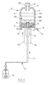
- a first fluid sampling and reinjection kit 10 according to the invention is schematically illustrated by the figure 1 .
- This kit 10 is advantageously intended for the implementation of a cosmetic treatment method, non-therapeutic, on a subject formed by a human or animal.
- the kit 10 comprises a first device 12 for sampling and reinjection, a mechanical injector 14, a vacuum pump 16 and a centrifuge 18
- the body fluid intended to be taken and reinjected by the device 12 is for example an adipose tissue of the dermis and / or the hypoderm of a human or animal, in particular intended to play the dual role of food reserve and protective layer against the cold.
- adipose tissue is generally referred to as "dermal fat,” “cover fat,” or “subcutaneous fat.”
- This fluid after sampling, is capable of being separated into several phases, of which at least one phase is compatible to be reinjected by the device 12 according to the invention.
- the fluid is a biological fluid such as a blood product, a culture medium or a figured element of the blood.
- the device 12 is preferably initially contained in a sterile package 20.
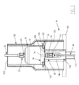
- It comprises an assembly 11 in one piece comprising a hollow syringe body 22, a piston 24 movably mounted in the syringe body 22 and, according to the invention, a dispensing assembly 26 carried by the piston 24.
- the device 12 further comprises a removable evacuation line 32, a first removable body fluid sampling line 34 and a second removable body fluid reinjection line 36.
- the syringe body 22 is for example made in one piece of a transparent material, such as glass or a plastic material. It is intended to be connected, in a first sampling step, to the vacuum pump 16 and the sampling line 34 for the removal of body fluid in the subject.
- the body 22 is then intended to be mounted in a cradle of the centrifuge 18 for the purpose of separating the fluid sampled in several phases.
- the body 22 is also intended to be connected to the injector 14 and the reinjection duct 36 to allow the reinjection of at least one phase of the body fluid into the subject.
- the body 22 has a tubular shape extending along an axis AA 'shown vertical on the figure 2 . It delimits internally a cavity 40 for receiving the body fluid. It comprises a peripheral wall 42 and a distal wall 44 distally sealing the peripheral wall 42.
- the cavity 40 is delimited externally by the peripheral wall 42 and distally by the distal wall 44. It opens upstream by a main proximal opening 46 formed at the proximal end of the wall 42.
- the distal opening 48 is formed in the distal wall 44. It is situated axially opposite the proximal opening 46.
- the distal opening 48 has a cross section smaller than the cross section of the main opening 46.
- the body 22 carries a distal connector 49 which projects from the distal wall 44 about the distal opening 48.
- the distal connector 49 is provided with a connecting tip 49A for removably connected to a conduit 32. , 34, 36.
- the tip 49A is also adapted to receive a selectively closing member of the opening 48 such as a plug or a valve.
- the distal connector 49 comprises a proximal section 49B projecting into the cavity 40 to guide the evacuation of fluid through the opening 48.
- the volume of the receiving cavity 40 is for example between 5 cm 3 and 300 cm 3 .
- the lateral wall 42 is externally provided with means 52 for locking the body 22 on the injector 14 and on a cradle of the centrifuge 18.
- means 52 are for example formed by a thread, or by a retaining flange 54 shown schematically on the figure 2 .
- the piston 24 has an outer cross section conjugate to the inner cross section of the cavity 40. It seals the cavity 40 in a proximal direction.
- the piston 24 is advantageously provided with hooking means 60 intended to be engaged with a movable actuating member present in the injector 14.
- the piston 24 is movably mounted in the cavity 40 along the axis A-A ', between a proximal position, located in the vicinity of the proximal opening 46, and a distal position, located in the vicinity of the distal wall 44.
- the piston 24 sealingly closes the cavity 40 with the exception of the dispensing assembly 26. This prevents the fluid present in the cavity 40 from escaping. through the proximal opening 46, except through the dispensing assembly 26.
- the piston 24 comprises a closing body 61, of external cross section conjugated to the internal cross section of the cavity 40.
- the piston 24 has an inner surface 61 A disposed in the cavity 40 and an opposite outer surface 61 B, in which are provided the attachment means 60 when present.
- the outer surface 61 B is intended to come into contact with the actuating member present on the injector 14.
- the dispensing assembly 26 comprises a channel 70 for fluid circulation formed through the piston 24, and advantageously, a proximal connection stitching 72.
- the circulation channel 70 is formed axially through the body 61 of the piston 24. It opens into the inner surface 61 A and into the outer surface 61 B. It fluidly connects the cavity 40 to the proximal stitching 72.
- the proximal stitching 72 projects outwardly from the outer surface 61 B. It is connected to the circulation channel 70. It is mounted movably together with the piston 24 during the displacement of the piston 24.
- Proximal stitching 72 is provided with a proximal endpiece 74 intended to be selectively connected to a pipe 34, 36, or to a shutter constituted for example by a plug or a valve.
- the channel 70 is substantially parallel to the axis A-A ', co-axially with the axis A-A'.
- the channel 70 is shifted transversely to the axis A-A 'or / and extends inclined relative to the axis A-A'.
- the evacuation line 32 is for example made based on a rigid tubing 103. It comprises an upstream endpiece 106 intended to be mounted on the distal tip 49A of the distal connector 49 and a downstream endpiece 108 intended to be connected to the vacuum pump 16.
- the vacuum pipe 32 is advantageously provided with a shut-off valve 109.
- the sampling line 34 comprises a connecting pipe 110, preferably flexible, and a picking needle 112 more rigid than the tubing 110.
- the needle 112 is constituted for example by a liposuction needle.
- the tubing 110 has an upstream endpiece 114 intended to be connected to the endpiece 74 of the proximal stitching 72 and / or to the endpiece 49A of the distal connector 49.
- the reinjection duct 36 comprises a reinjection flexible pipe 116 provided downstream of a reinjection needle 118, which is stiffer than the pipe 116.
- the reinjection duct 36 is advantageously distinct from the sampling duct 34.
- the duct 34 forms both the sampling duct and the reinjection duct.
- the reinjection tubing 116 is provided with a nozzle 120 intended to be connected to the tip 49A of the distal connector 49 and / or to the tip 74 of the proximal stitching 72.
- a reinjected body fluid flow control module 122 is disposed on the reinjection duct 36.
- This module 122 comprises a control member 124 controllable by an operator to control the flow flowing through the tubing 116 and to through the reinjection needle 118.
- control module 122 is arranged upstream of the reinjection duct 36, between the distal connector 49 and the nozzle 114, the control member 124 being remote relative to the module 122.
- the control member 124 is for example a button, as shown on the figure 2 .
- the control member 124 is a pedal, in the case where the operator must have both hands.
- Each of the lines 32, 34, 36 is intended to be removably and reversibly mounted respectively on one or the other of the distal connector 49 and the proximal stitching 72.
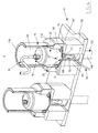
- the injector 14 comprises a frame 128, a support 130 for receiving the syringe body 22, a member 132 for actuating the piston 24 and a cradle 133 for receiving the actuating member 132.
- the injector 14 further comprises means 134 for controlling the displacement of the actuating member 132.
- the support 130 is for example formed by a half-drum mounted on the cradle 133.
- the support 130 thus advantageously has a lateral opening 136 for introducing the body 22 and an upper opening 138 for passage of a pipe 34, 36.
- the support 130 has locking means complementary to the locking means 52 of the body 22 arranged in the vicinity of the proximal opening 46.
- the complementary locking means are formed in the support 130. They are for example formed by slots 140 defining a retaining shoulder of the locking means 52.
- the body 40 can thus be introduced into the support 130 via the lateral opening 136 by releasably engaging the locking means 52 in the slots 140.
- the receiving cradle 133 of the actuating member is disposed between the frame 128 and the support 130. It delimits an upper bearing surface 142 of the body 40 and a central lumen 144 for passage of the actuating member 130 .
- the lumen 144 emerges opposite the support 130. It opens by a lateral passage located under the lateral opening 136 to allow the passage of the proximal stitching 72 and possibly a duct 32, 34, 36 during the insertion of the body. 22 in the support 130.
- the actuating member 132 comprises a rod 146 defining a housing 148.
- the housing 148 is intended to receive the proximal stitching 72 and possibly a pipe 32, 34, 36.
- the rod 146 extends through the frame 128, through the cradle 133, and through the support 130 when it is deployed relative to the frame 128. It has an upper surface 150 bearing on the piston 24. The upper surface 150 is located at its free end.
- the upper surface 150 is intended to cooperate with the attachment means 60 to move the piston 24 in the cavity 40.
- the housing 148 is formed by an axial notch.
- the housing 148 opens axially along the axis of the rod 146 in the upper surface 150 via an axial opening intended to extend facing the outer surface 61 B of the piston 24.
- the housing 148 opens transversely through a lateral opening 152 allowing the passage of a pipe 34, 36 and the insertion of the proximal stitching 72.
- the lateral opening 152 extends opposite the lateral passage through which the lumen 144 opens.
- the actuating member 132 is thus movable along an axis AA 'in the cradle 133 and in the support 130 between a retracted position in the cradle 133 and a deployed position in the support 130, via the means 134.
- the actuating member 132 moves the piston 24 from its position proximal to its distal position.
- the actuating member 132 moves together the proximal stitching 72 and possibly the pipe 32, 34, 36 mounted on the tip 74 of the stitching 72.
- the syringe body 22 can be mounted reversibly in the support 130 on the injector 14.
- the actuating member 132 is able to cooperate with the engagement means 60 on the piston 24 to move the piston 24 from its proximal position to its distal position at a controlled rate.
- the vacuum pump 16 is able to generate a vacuum, for example of the order of -950 mbar relative in the receiving cavity 40, when the vacuum pipe 32 is connected to both the vacuum pump 16 and at the distal connector 49, and when the valve 109 is open.
- the injector 14 and the vacuum pump 16 are received on the same frame 156 to be movable together.
- the centrifuge 18 comprises at least one cradle 157 (visible on the Figure 1 ) adapted to receive fixedly the syringe body 22, the sampling assembly 26 and the distal connector 49.
- the cradle 157 has a receiving housing (not shown) for receiving the proximal end of the syringe body 22 and the locking means 52.
- the housing of the cradle 157 is provided with locking means complementary to the locking means 52. It further comprises a locking stop in position of the piston 24 to prevent its movement through the proximal opening 46.
- the syringe body 22 is reversibly locked in position and is rotatable to cause phase separation within the fluid contained in the receiving cavity 40.
- a device 12 for sampling and reinjection advantageously contained in a sterile package 20, is provided.
- the sampling line 34 is entered by the operator. This then pierces the skin 160 of the subject undergoing the cosmetic treatment with the aid of the needle 112, to take adipose tissue 162 under the skin 160.
- the piston 24 initially occupies its proximal position in the vicinity of the proximal opening 46.
- fluid 163 is sucked successively through the sampling needle 112, the sampling tube 110, the proximal stitching 72 and the circulation channel 70, in order to progressively fill the cavity 40, from below at the top, as illustrated by figure 5 .
- the operator dismantles the sampling line 34 and the evacuation line 32. It closes the distal connector 49 and the proximal stitching 72, for example by means of a plug or a valve (not shown).
- the operator grasps the syringe body 22 closed downstream by the piston 24 and introduces the proximal end of the body 22 into a cradle 157 of the centrifuge 18.
- the piston 24 is then immobilized axially in the cradle 157.
- the operator activates the centrifuge 18 to separate the fluid 163 contained in the receiving cavity 40 in several phases 164A, 164B, 164C represented on the
- the operator dismounts the syringe body 22 to extract it out of the centrifuge 18, releasing the locking means. Then, as illustrated by figure 5 , the operator connects an evacuation line, for example formed by the sampling line 34, to the proximal stitching 72.
- the upstream endpiece 114 of the tubing 110, the proximal stitching 72 and the upstream portion of the tubing 110 are then received in the housing 148.
- a portion of the tubing 110 protrudes out of the housing 148 through the lumen 144, and outside the cradle 133.
- the operator activates the control means 134 of the injector 14 to move the piston 24 along the axis AA 'towards the distal end of the body 22.
- the lower phase 164A is evacuated successively through the channel 70, the sewing 72, then through the discharge pipe to a container 160, to be eliminated.
- the operator closes the proximal stitching 72. He assembles a discharge line, for example the sampling line 34, on the distal connector 49 of the body 22.
- the operator again actuates the control means 134 to move the piston 24 towards the distal end of the body 22 and thus evacuate the upper phase 164C through the distal connection 49 and then through the evacuation duct 34.
- the operator dismantles the evacuation line and raises the reinjection duct 36 to the distal connector 49.
- the upper surface of the intermediate phase 164B is then located at the proximal section 49B of the distal connector 49.
- the operator pricks the skin 160 of the subject in a region distinct from that where the adipose tissue 162 has been removed, for example at the level of the face, in the mammary glands or in a fleshy part.
- the device 12 according to the invention thus makes it possible successively to carry out all the operations necessary for sampling, centrifugation, and reinjection of the fluid, without having to change the container fluid.
- the asepsis of the operation is strengthened and the risk of microbial contamination is very low.
- the device 12 is extremely simple to handle, especially in the environment of an operating room.
- the presence of the dispensing assembly 26 integral with the piston 24 eliminates all the phases of the fluid that are not desired to inject only one or more selected phases (s).
- the device 12 thus allows clean and simple manipulation of the body fluid, so without risk of leakage or contamination.
- the body fluid taken from a first living being is not necessarily reinjected into this first living being, but is reinjected into a second living being.
- the distribution assembly 26 is able to selectively discharge an upstream portion of the fluid present in the receiving cavity 40, independently of a downstream portion of the fluid located between the upstream portion and the or each opening distal 48.
- the upstream portion of the fluid is advantageously constituted by the lower phase 164A which can be discharged through the distribution assembly 26, independently of the intermediate phase 164B, and without having to extract the intermediate phase 164B through a distal opening 48 .
- a second kit 210 according to the invention is illustrated by the Figure 8 .
- This kit 210 is similar to the first necessary 10.
- the device 12 for sampling and reinjecting the second necessary 210 differs from the device 12 of the first necessary 10 by the characteristic that the distribution assembly 26 is offset axially with respect to the axis of the piston 24.
- the operation of the second necessary 210 is similar to that of the first necessary 10.
- the device 12 can then be mounted on an injector 14 whose actuator 132 is not necessarily provided with a housing 148 for receiving the proximal stitching 72.
- Proximal stitching 72 protrudes away from actuator 132 relative to plunger 24.
- the body 22 has an additional distal opening 170 distinct from the distal opening 48.
- the additional distal opening 170 opens into an auxiliary connection 172 mounted on the body 22 and provided with a connecting end 174 to a pipe 32, 34 , 36.
- auxiliary opening 170 can be connected to the vacuum line 32, and the main opening 48 can be connected to the sampling line 34 and / or the reinjection line 36. This variant also applies to the first necessary 10.
- a third necessary according to 240 according to the invention is illustrated by the Figure 9 .
- the piston 24 comprises, in addition to the closure body 61, a proximal rod 242 for actuating the piston 24 which protrudes externally from the closure body 61.
- the channel 70 extends successively through the body 61, then through the rod 242, to open out of the rod 242, preferably at the proximal end 244 of the stem 242.
- the proximal stitching 72 is connected to the stem 242 .
- the proximal connector 72 projects axially, in the axis of the rod 242 of the piston.
- the proximal connector 72 protrudes transversely with respect to the axis of the rod 242.
- the channel 70 is then bent.
- the operation of the third necessary 240 is moreover analogous to that of the first necessary 10.
- the piston 24 is not actuated by an injector 14. It is actuated manually by an operator using his fingers.
- a fourth kit 250 according to the invention is illustrated by the Figure 10 .
- the device 12 of the fourth kit 250 comprises at least one protective bladder 252A, 252B intended to ensure the asepsis when connecting the lines 32, 34, 36 respectively to one and / or the other of the distal connector 49 and the proximal stitching 72.
- the device 12 shown on the Figure 10 advantageously comprises a first bladder 252A mounted on the distal connector 49 and a second bladder 252B mounted on the proximal stitching 72.
- Each bladder 252A, 252B is formed by a flexible envelope 254, advantageously transparent.
- the flexible envelope 254 delimits a substantially gaseous interior gas space 256.
- the casing 254 of the first bladder 252A is sealingly mounted about a distal portion of the distal connector 49. It receives the tip 49A of the distal connector 49 in its internal volume 256.
- the first bladder 252A is also sealingly mounted around the proximal portion of the vacuum line 32. It is advantageously sealingly mounted about a proximal end of a discharge line 258.
- the volume 256 thus advantageously receives the upstream endpiece 106 of the evacuation pipe and the upstream endpiece 260 of the evacuation pipe 258.
- the bladder 252A also contains at least one pocket 262 for recovering a phase to be eliminated, provided with a tip 264 at its end.
- the tip 49A of the distal connector 49 can be selectively connected to one of the tips 106, 260, 264 contained in the bladder 252A during the different phases of the process. This operation can be performed without the operator having to touch the end pieces 106, 260, 264 by simply deforming the envelope 254.
- the envelope 254 of the second bladder 252B contains the tip 74 of the proximal stitching.
- This tip 74 may be selectively connected to a nozzle 260 of a discharge pipe 258 or to a tip 264 of a pocket 262, the ends 74, 260, 264 being received in the casing 254 of the second bladder 252B.
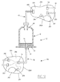
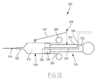
- a fifth kit 310 according to the invention is illustrated by the figures 11 and 12 .
- the fifth necessary 310 comprises a first device 12 for sampling and reinjection, intended to be removably mounted on a mechanical injector 14.
- the fifth necessary 310 differs from the first necessary 10 in that it comprises an additional device 312 manual adjustment of the flow of fluid reinjected into the subject.
- the device 312 is connected to the reinforcement member 118, which is advantageously a needle, or a fine cannula.
- the additional device 312 is formed by a syringe which carries the reinjection member 118.
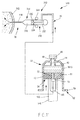
- the device 312 comprises an additional hollow body 314 delimiting an interior volume 316 of flow control.
- the device 312 further comprises a piston 318 movable in the body 316 to shut off the interior volume 316 upstream.
- the device 312 also advantageously comprises a releasable mechanism 319 for locking the piston 318 in position relative to the body 314.
- the additional hollow body 314 has a tubular shape. It defines a distal opening 320 connected to the needle 118, and a proximal opening 322 through which the piston 318 is inserted into the body 314.
- the body 314 comprises, around its proximal opening 322, a flange 324 capable of being gripped by the fingers of a user to hold the hollow body 314 in position.
- the piston 318 includes a closure head 330 of the volume 316, inserted in the body 114 and an actuating rod 332, able to project out of the body 314 to be pushed by a finger of a user.
- the piston 318 internally delimits a channel 334 supplying fluid into the volume 316.
- the channel 334 opens downstream through a downstream orifice 336 located in the volume 316, and upstream, by an upstream orifice 338 located outside the body 314.
- the upstream orifice 338 is intended to be connected to the fluid reinjection duct 36. In the example shown on the figure 12 it opens out transversely with respect to an axis of the piston 318.
- the mechanism 319 includes a locking rack 340 on the piston 318, and a movable member 342 for engaging the rack 340, mounted on the body 314.
- the engagement member 342 is movable between a release position of the piston 318 in which it is located away from the rack 340, and a plurality of locking positions of the piston 318 relative to the body 314, wherein it is engaged with at least one tooth of the rack 340.
- the reinjection duct 36 is connected upstream to the circulation channel 70 formed in the piston 24. It is housed at least partially in the housing 148 formed in the rod 146 of the actuating member 132.
- the operation of the fifth kit 310 according to the invention is similar to that of the first necessary 10 until the end of the step of separation and elimination of unwanted phases 164A, 164C for reinjection into the subject.
- the operation of the fifth necessary 310 according to the invention differs from the operation of the first necessary 10 during the reinjection step.
- the operator connects the reinjection duct 36 to the body 22 of the device 12.
- he assembles the upstream end of the duct 36 on the connector 72 to connect the duct 70 to the duct 36. it fixes the downstream end of the reinjection duct 36 on the piston 318 of the additional device 312 to connect the reinjection duct 36 to the channel 334. It also closes the distal connector 49.
- the operator refills the interior volume 316 of the additional device 312.
- the operator activates the injector 14, which causes a displacement of the rod 146 of the actuating member 132 inward of the volume 40 to push the piston 24.
- This displacement of the piston 24 generates the evacuation of fluid 164B through line 36, and through channel 334 to internal volume 316.
- a first mode of operation when constant flow fluid injection is required, the operator sets the constant speed of movement of the actuator 132, and holds the piston 318 of the additional device 312 in position by to the body 314.
- This holding in position is provided either manually or using the mechanism 319.
- the internal volume 316 remains constant.
- An upper flow rate of fluid is then ejected punctually out of the additional device 312, which allows for example to perform a rapid filling of a cavity or a body area to increase its volume.
- a third mode of operation when the injected fluid flow must be punctually reduced, the operator releases the piston 318 from the additional device 312 and leaves it free to move away from the downstream opening 320. This causes the increase in the intermediate volume 316 and the corresponding decrease in the fluid flow rate extracted at Through the needle 118. In a variant, the operator manually moves the piston 318 away from the downstream opening 320.
- Such an operating mode makes it possible to precisely control the quantity of fluid extracted from the additional device 312, in particular for an accurate injection of additional fluid into the subject.
- an additional device 312 allows a precise adjustment of the amount of fluid extracted from the kit 310, for reinjection into a subject. This adjustment is carried out manually by a simple actuation of the piston 318 with the aid of the fingers of the operator, without having to act on the adjustment of the injector 14.
Landscapes
- Health & Medical Sciences (AREA)
- Heart & Thoracic Surgery (AREA)
- Life Sciences & Earth Sciences (AREA)
- Animal Behavior & Ethology (AREA)
- Engineering & Computer Science (AREA)
- Anesthesiology (AREA)
- Biomedical Technology (AREA)
- Hematology (AREA)
- Veterinary Medicine (AREA)
- Vascular Medicine (AREA)
- General Health & Medical Sciences (AREA)
- Public Health (AREA)
- Surgery (AREA)
- Physics & Mathematics (AREA)
- Fluid Mechanics (AREA)
- Infusion, Injection, And Reservoir Apparatuses (AREA)
- Sampling And Sample Adjustment (AREA)
Applications Claiming Priority (1)
| Application Number | Priority Date | Filing Date | Title |
|---|---|---|---|
| FR1159876A FR2981852B1 (fr) | 2011-10-31 | 2011-10-31 | Dispositif de prelevement et de reinjection d'un fluide , injecteur et necessaire de prelevement associes |
Publications (2)
| Publication Number | Publication Date |
|---|---|
| EP2586476A2 true EP2586476A2 (de) | 2013-05-01 |
| EP2586476A3 EP2586476A3 (de) | 2014-06-25 |
Family
ID=47071188
Family Applications (1)
| Application Number | Title | Priority Date | Filing Date |
|---|---|---|---|
| EP12190658.0A Withdrawn EP2586476A3 (de) | 2011-10-31 | 2012-10-30 | Vorrichtung zur Entnahme und zur Wiedereinspritzung von Fettgewebe, entsprechender Einspritzer und entsprechende Entnahmevorrichtungen |
Country Status (3)
| Country | Link |
|---|---|
| US (1) | US20130123683A1 (de) |
| EP (1) | EP2586476A3 (de) |
| FR (1) | FR2981852B1 (de) |
Families Citing this family (2)
| Publication number | Priority date | Publication date | Assignee | Title |
|---|---|---|---|---|
| WO2017040202A1 (en) * | 2015-08-28 | 2017-03-09 | Crisi Medical Systems, Inc. | Flow sensor system including transmissive connection |
| CN111317517B (zh) * | 2020-02-27 | 2022-09-09 | 南京亿科人群健康研究院有限公司 | 一种用于脂肪组织提取和再注入的仪器 |
Family Cites Families (8)
| Publication number | Priority date | Publication date | Assignee | Title |
|---|---|---|---|---|
| FR844720A (fr) * | 1938-10-14 | 1939-07-31 | Perfectionnements aux seringues et, plus particulièrement, aux seringues pour la transfusion du sang | |
| US3596652A (en) * | 1968-10-14 | 1971-08-03 | Bio Science Labor | Fluid separatory device |
| IT1292763B1 (it) * | 1997-06-11 | 1999-02-11 | Luciano Centanni | Involucro sterile per la protezione di apparecchi medicali durante l'uso. |
| FR2764809B1 (fr) * | 1997-06-18 | 1999-10-15 | Marie Anne Raybaut | Dispositif destine a maintenir sterile un moyen de liaison entre un tuyau en amont et au moins un tuyau en aval |
| US6716187B1 (en) * | 1999-07-08 | 2004-04-06 | Implant Innovations, Inc. | Platelet concentration syringe kit |
| KR100473568B1 (ko) * | 2003-01-25 | 2005-03-10 | 이희영 | 밀폐형 지방이식 시스템 |
| US20050124073A1 (en) * | 2003-12-09 | 2005-06-09 | Entire Interest | Fat collection and preparation system and method |
| JP4769253B2 (ja) * | 2004-11-19 | 2011-09-07 | カーリン メディカル インコーポレイテッド | 体積管理注入装置 |
-
2011
- 2011-10-31 FR FR1159876A patent/FR2981852B1/fr not_active Expired - Fee Related
-
2012
- 2012-10-30 EP EP12190658.0A patent/EP2586476A3/de not_active Withdrawn
- 2012-10-31 US US13/664,697 patent/US20130123683A1/en not_active Abandoned
Non-Patent Citations (1)
| Title |
|---|
| None |
Also Published As
| Publication number | Publication date |
|---|---|
| US20130123683A1 (en) | 2013-05-16 |
| FR2981852A1 (fr) | 2013-05-03 |
| EP2586476A3 (de) | 2014-06-25 |
| FR2981852B1 (fr) | 2014-12-05 |
Similar Documents
| Publication | Publication Date | Title |
|---|---|---|
| CA2344214C (fr) | Seringues pour l'administration de formulations pateuses ou semi-solides | |
| EP0294272B1 (de) | Nadelloser Injektor, insbesondere für die zahnmedizinische Anwendung | |
| EP2296733B1 (de) | Vorrichtung zur injektion einer medizinischen flüssigkeit zur medizinischen verwendung | |
| KR102102221B1 (ko) | 인간 또는 동물 조직의 혈액 또는 다른 물질을 추출, 저장 및/또는 처리하고, 혈액 화합물 또는 다른 생물학적 화합물을 적용하기 위한 장치 | |
| FR2905274A1 (fr) | Kit d'injection automatique | |
| FR2830455A1 (fr) | Catheter a outil d'extremite perforant ou piquant retractable | |
| FR2522508A1 (fr) | Ensemble pour l'introduction de catheters | |
| EP3697478A1 (de) | Manuelle injektionsvorrichtung | |
| WO2021209721A1 (fr) | Seringue d'injection | |
| WO1998056437A1 (fr) | Seringue d'injection perfectionnee, comportant des moyens d'aspiration | |
| EP2586476A2 (de) | Vorrichtung zur Entnahme und zur Wiedereinspritzung von Fettgewebe, entsprechender Einspritzer und entsprechende Entnahmevorrichtungen | |
| EP0725600B1 (de) | Chirurgisches instrument zur behandlung einer wasser enthaltenden zyste | |
| FR2826871A1 (fr) | Unite a aiguille d'injection pour appareil automatique et portable a seringue | |
| EP2750755B1 (de) | Kit zum manövrieren eines elements im körper eines patienten mit einer implantierbaren kammer | |
| FR2889070A1 (fr) | Appareil d'aspiration et d'ejection utilisable pour les soins | |
| FR2743300A1 (fr) | Dispositif de perfusion | |
| EP3752230B1 (de) | Injektionskopf zur injektion einer flüssigen substanz und zur überwachung der injektionsstelle vor injektion der flüssigen substanz und spritze mit einem solchen kopf | |
| US20250176999A9 (en) | Insertion tool with a dissector | |
| WO2023105129A1 (fr) | Machine pour la purification d'un tissu adipeux et l'introduction du tissu adipeux purifie dans le corps d'un patient | |
| JP2019506216A (ja) | フォームを分配する装置および方法 | |
| FR2696096A1 (fr) | Seringue, notamment pour usage dentaire. | |
| FR2911784A1 (fr) | Appareil d'aspiration et de diffusion de fluide pour soins corporels. | |
| FR2905603A1 (fr) | Site implantable a obturateur mobile. | |
| FR3063431A1 (fr) | Pousse seringue ergonomique | |
| FR2615739A1 (fr) | Appareil d'injection de liquide, sans aiguille notamment a usage de soins dentaires |
Legal Events
| Date | Code | Title | Description |
|---|---|---|---|
| PUAI | Public reference made under article 153(3) epc to a published international application that has entered the european phase |
Free format text: ORIGINAL CODE: 0009012 |
|
| AK | Designated contracting states |
Kind code of ref document: A2 Designated state(s): AL AT BE BG CH CY CZ DE DK EE ES FI FR GB GR HR HU IE IS IT LI LT LU LV MC MK MT NL NO PL PT RO RS SE SI SK SM TR |
|
| AX | Request for extension of the european patent |
Extension state: BA ME |
|
| PUAL | Search report despatched |
Free format text: ORIGINAL CODE: 0009013 |
|
| AK | Designated contracting states |
Kind code of ref document: A3 Designated state(s): AL AT BE BG CH CY CZ DE DK EE ES FI FR GB GR HR HU IE IS IT LI LT LU LV MC MK MT NL NO PL PT RO RS SE SI SK SM TR |
|
| AX | Request for extension of the european patent |
Extension state: BA ME |
|
| RIC1 | Information provided on ipc code assigned before grant |
Ipc: A61M 5/168 20060101ALI20140521BHEP Ipc: A61M 39/00 20060101ALN20140521BHEP Ipc: A61M 39/18 20060101ALN20140521BHEP Ipc: A61M 5/145 20060101AFI20140521BHEP Ipc: A61M 5/20 20060101ALN20140521BHEP Ipc: A61M 5/315 20060101ALI20140521BHEP Ipc: A61M 1/00 20060101ALI20140521BHEP Ipc: A61M 5/24 20060101ALN20140521BHEP Ipc: A61B 17/00 20060101ALN20140521BHEP Ipc: A61M 39/16 20060101ALN20140521BHEP |
|
| STAA | Information on the status of an ep patent application or granted ep patent |
Free format text: STATUS: THE APPLICATION IS DEEMED TO BE WITHDRAWN |
|
| 18D | Application deemed to be withdrawn |
Effective date: 20150106 |