EP2586482B1 - Ensemble de boîtier avec une substance pour éliminer d'un composant indésirable du gaz respiratoire d'un flux de gaz respiratoire et agencement pour ventiler les poumons d'un sujet - Google Patents
Ensemble de boîtier avec une substance pour éliminer d'un composant indésirable du gaz respiratoire d'un flux de gaz respiratoire et agencement pour ventiler les poumons d'un sujet Download PDFInfo
- Publication number
- EP2586482B1 EP2586482B1 EP11186276.9A EP11186276A EP2586482B1 EP 2586482 B1 EP2586482 B1 EP 2586482B1 EP 11186276 A EP11186276 A EP 11186276A EP 2586482 B1 EP2586482 B1 EP 2586482B1
- Authority
- EP
- European Patent Office
- Prior art keywords
- opening
- gas
- housing assembly
- channel
- assembly according
- Prior art date
- Legal status (The legal status is an assumption and is not a legal conclusion. Google has not performed a legal analysis and makes no representation as to the accuracy of the status listed.)
- Not-in-force
Links
- 239000000126 substance Substances 0.000 title claims description 23
- 210000004072 lung Anatomy 0.000 title claims description 22
- 230000000241 respiratory effect Effects 0.000 title claims description 20
- 230000029058 respiratory gaseous exchange Effects 0.000 claims description 51
- 238000005452 bending Methods 0.000 claims description 2
- 239000007789 gas Substances 0.000 description 98
- CURLTUGMZLYLDI-UHFFFAOYSA-N Carbon dioxide Chemical compound O=C=O CURLTUGMZLYLDI-UHFFFAOYSA-N 0.000 description 42
- 239000001569 carbon dioxide Substances 0.000 description 21
- 229910002092 carbon dioxide Inorganic materials 0.000 description 21
- 239000006096 absorbing agent Substances 0.000 description 14
- GQPLMRYTRLFLPF-UHFFFAOYSA-N Nitrous Oxide Chemical compound [O-][N+]#N GQPLMRYTRLFLPF-UHFFFAOYSA-N 0.000 description 10
- 239000003193 general anesthetic agent Substances 0.000 description 8
- 238000004519 manufacturing process Methods 0.000 description 8
- 239000008187 granular material Substances 0.000 description 7
- 206010002091 Anaesthesia Diseases 0.000 description 6
- 230000037005 anaesthesia Effects 0.000 description 6
- 239000002250 absorbent Substances 0.000 description 5
- 230000002745 absorbent Effects 0.000 description 5
- QVGXLLKOCUKJST-UHFFFAOYSA-N atomic oxygen Chemical compound [O] QVGXLLKOCUKJST-UHFFFAOYSA-N 0.000 description 5
- 239000001272 nitrous oxide Substances 0.000 description 5
- 239000001301 oxygen Substances 0.000 description 5
- 229910052760 oxygen Inorganic materials 0.000 description 5
- 239000003983 inhalation anesthetic agent Substances 0.000 description 4
- 238000009423 ventilation Methods 0.000 description 4
- KWYUFKZDYYNOTN-UHFFFAOYSA-M Potassium hydroxide Chemical compound [OH-].[K+] KWYUFKZDYYNOTN-UHFFFAOYSA-M 0.000 description 3
- HEMHJVSKTPXQMS-UHFFFAOYSA-M Sodium hydroxide Chemical compound [OH-].[Na+] HEMHJVSKTPXQMS-UHFFFAOYSA-M 0.000 description 3
- 239000000463 material Substances 0.000 description 3
- 239000000203 mixture Substances 0.000 description 3
- 230000037361 pathway Effects 0.000 description 2
- 238000007789 sealing Methods 0.000 description 2
- 239000007787 solid Substances 0.000 description 2
- 230000032258 transport Effects 0.000 description 2
- PIWKPBJCKXDKJR-UHFFFAOYSA-N Isoflurane Chemical compound FC(F)OC(Cl)C(F)(F)F PIWKPBJCKXDKJR-UHFFFAOYSA-N 0.000 description 1
- CBENFWSGALASAD-UHFFFAOYSA-N Ozone Chemical compound [O-][O+]=O CBENFWSGALASAD-UHFFFAOYSA-N 0.000 description 1
- 239000011358 absorbing material Substances 0.000 description 1
- 150000001412 amines Chemical class 0.000 description 1
- 239000003994 anesthetic gas Substances 0.000 description 1
- 230000000712 assembly Effects 0.000 description 1
- 238000000429 assembly Methods 0.000 description 1
- 239000008280 blood Substances 0.000 description 1
- 210000004369 blood Anatomy 0.000 description 1
- 230000017531 blood circulation Effects 0.000 description 1
- 210000004556 brain Anatomy 0.000 description 1
- AXCZMVOFGPJBDE-UHFFFAOYSA-L calcium dihydroxide Chemical compound [OH-].[OH-].[Ca+2] AXCZMVOFGPJBDE-UHFFFAOYSA-L 0.000 description 1
- 239000000920 calcium hydroxide Substances 0.000 description 1
- 229910001861 calcium hydroxide Inorganic materials 0.000 description 1
- 229960003537 desflurane Drugs 0.000 description 1
- DPYMFVXJLLWWEU-UHFFFAOYSA-N desflurane Chemical compound FC(F)OC(F)C(F)(F)F DPYMFVXJLLWWEU-UHFFFAOYSA-N 0.000 description 1
- 238000010586 diagram Methods 0.000 description 1
- 238000007599 discharging Methods 0.000 description 1
- 239000013013 elastic material Substances 0.000 description 1
- 229960000305 enflurane Drugs 0.000 description 1
- JPGQOUSTVILISH-UHFFFAOYSA-N enflurane Chemical compound FC(F)OC(F)(F)C(F)Cl JPGQOUSTVILISH-UHFFFAOYSA-N 0.000 description 1
- 239000006260 foam Substances 0.000 description 1
- 239000005431 greenhouse gas Substances 0.000 description 1
- 150000008282 halocarbons Chemical group 0.000 description 1
- 229960003132 halothane Drugs 0.000 description 1
- BCQZXOMGPXTTIC-UHFFFAOYSA-N halothane Chemical compound FC(F)(F)C(Cl)Br BCQZXOMGPXTTIC-UHFFFAOYSA-N 0.000 description 1
- 238000002347 injection Methods 0.000 description 1
- 239000007924 injection Substances 0.000 description 1
- 229960002725 isoflurane Drugs 0.000 description 1
- 239000007788 liquid Substances 0.000 description 1
- 230000004060 metabolic process Effects 0.000 description 1
- 239000002808 molecular sieve Substances 0.000 description 1
- 238000004806 packaging method and process Methods 0.000 description 1
- 230000035515 penetration Effects 0.000 description 1
- 229960002078 sevoflurane Drugs 0.000 description 1
- DFEYYRMXOJXZRJ-UHFFFAOYSA-N sevoflurane Chemical compound FCOC(C(F)(F)F)C(F)(F)F DFEYYRMXOJXZRJ-UHFFFAOYSA-N 0.000 description 1
- URGAHOPLAPQHLN-UHFFFAOYSA-N sodium aluminosilicate Chemical compound [Na+].[Al+3].[O-][Si]([O-])=O.[O-][Si]([O-])=O URGAHOPLAPQHLN-UHFFFAOYSA-N 0.000 description 1
- HUAUNKAZQWMVFY-UHFFFAOYSA-M sodium;oxocalcium;hydroxide Chemical compound [OH-].[Na+].[Ca]=O HUAUNKAZQWMVFY-UHFFFAOYSA-M 0.000 description 1
- 239000006200 vaporizer Substances 0.000 description 1
- 239000003039 volatile agent Substances 0.000 description 1
- XLYOFNOQVPJJNP-UHFFFAOYSA-N water Substances O XLYOFNOQVPJJNP-UHFFFAOYSA-N 0.000 description 1
- 229910001868 water Inorganic materials 0.000 description 1
Images


Classifications
-
- A—HUMAN NECESSITIES
- A61—MEDICAL OR VETERINARY SCIENCE; HYGIENE
- A61M—DEVICES FOR INTRODUCING MEDIA INTO, OR ONTO, THE BODY; DEVICES FOR TRANSDUCING BODY MEDIA OR FOR TAKING MEDIA FROM THE BODY; DEVICES FOR PRODUCING OR ENDING SLEEP OR STUPOR
- A61M16/00—Devices for influencing the respiratory system of patients by gas treatment, e.g. ventilators; Tracheal tubes
- A61M16/22—Carbon dioxide-absorbing devices ; Other means for removing carbon dioxide
-
- A—HUMAN NECESSITIES
- A61—MEDICAL OR VETERINARY SCIENCE; HYGIENE
- A61M—DEVICES FOR INTRODUCING MEDIA INTO, OR ONTO, THE BODY; DEVICES FOR TRANSDUCING BODY MEDIA OR FOR TAKING MEDIA FROM THE BODY; DEVICES FOR PRODUCING OR ENDING SLEEP OR STUPOR
- A61M16/00—Devices for influencing the respiratory system of patients by gas treatment, e.g. ventilators; Tracheal tubes
- A61M16/08—Bellows; Connecting tubes ; Water traps; Patient circuits
- A61M16/0883—Circuit type
- A61M16/0891—Closed circuit, e.g. for anaesthesia
Definitions
- the disclosure relates generally to a housing assembly for a substance removing an undesired respiratory gas component of a respiratory gas flow.
- the housing assembly includes a body having a space for receiving the substance and having a first end and a second end, which is opposite the first end, allowing the respiration gas flow between these ends, a first wall surrounding at least part of the space, and a first opening in the flow communication with the first end and with outside the housing.
- the housing assembly includes a channel in flow communication with the second end and which channel includes a passage surrounded at least partly by a second wall for guiding the gas flow, and a second opening in flow communication with the passage.
- the disclosure also relates to an arrangement for ventilating lungs of a subject.
- Anesthesia machines are optimized for delivering anesthesia to a patient using volatile anesthetic agent liquids.
- the anesthetic agent is vaporized and mixed into the breathing gas stream in a controlled manner to provide a gas mixture for anesthetizing the patient for a surgical operation.
- the most common volatile anesthetic agents are halogenated hydrocarbon chains, such as halothane, enflurane, isoflurane, sevoflurane and desflurane.
- nitrous oxide (N 2 O) can be counted in this group of volatile anesthetic agents, although the high vapor pressure of nitrous oxide causes nitrous oxide to vaporize spontaneously in the high pressure gas cylinder, wherefrom it can be directly mixed as gas with oxygen.
- the anesthetizing potency of nitrous oxide alone is seldom enough to anesthetize a patient and therefore another volatile agent is used to support that.
- anesthesia machines have been developed to minimize the consumption of the gases.
- a defined brain partial pressure for the anesthetic agent is required. This partial pressure is maintained by keeping the anesthetic agent partial pressure in the lungs adequate.
- the lung and body partial pressures are equal, and no net exchange of the anesthetic agent occurs between the blood and the lungs.
- continuous lung ventilation is required.
- Anesthesia machines are designed to provide oxygen to the patient and eliminate carbon dioxide (CO2), while preserving the anesthetic gases.
- CO2 carbon dioxide
- a re-breathing circuit is used.
- exhaled gas is reintroduced for inhalation.
- carbon dioxide must be removed from the gas, which is done with a carbon dioxide absorber.
- the gas is supplied with additional oxygen and anesthetic agents based upon the patient demand.
- the additional gas flow added to the re-breathing circuit can be less than 0.5 L/min although the patient ventilation may be 5-10 L/min.
- Such ventilation of the lung is carried out using a ventilator pushing inhalation gas with overpressure to patient lungs and then allowing that to flow out passively from the pressurized lungs to the breathing circuit.
- Ventilation carries the breathing circuit oxygen to lungs for uptake to be burned in body metabolism.
- the outcome of this is CO2 that blood circulation transports to lungs wherefrom it becomes carried out with exhalation gas.
- the gas Before re-inhalation the gas is guided through absorber for CO2 removal. Effective CO2 removal requires close contact with the breathing gas and the removing substance. To provide large contact area, the removing substance is therefore a surface of porous structure of granules that fill the cartridge. The form of this granular structure is guided by the flow resistance, the limitation of which is one key design goals of the breathing circuit. In absorber optimized for minimal resistance the gas flow path through the stacked granules is short and the flow distributes to wide area. In such structure the gas flows slowly because of large surface area providing time for reaction between the gas and absorbent granules.
- the absorbers tend to have empty space above the granules. If the gas inlet and outlet to the absorber would be aligned to allow horizontal flow penetration through the cartridge, the flow would favor this empty space and the CO2 would leak through without getting absorbed. Therefore the gas flow must always penetrate through the absorbent on vertical direction.
- Absorber canisters have two gas connections: One inlet for the gas flow carrying carbon-dioxide and one outlet. Between inlet and outlet the canister has a gas pathway. The absorber granules form part of this pathway during which the carbon dioxide is removed from the gas.
- the pre-packed canisters may weight over 1 kg thus the design must take into consideration the handling during assembly and disassembly to the breathing circuit.
- This assembly must provide gas-tight connection between the cartridge and the rest of the breathing system taking into consideration of all manufacturing tolerances within the breathing system and the disposable absorber.
- the absorber canister interfaces with breathing system through valves that automatically guide the gas flow through the absorber when the absorber is installed on place and re-directs to absorber bypass channel when the canister is removed. Once installed on place the canister must seal to the receptacles on the breathing circuit to allow tight connection. This sealing requirement sets tight tolerances for the joint to mate exactly the breathing circuit and the canister. Low cost requirement of disposable canister however does not allow tight manufacturing tolerances.
- CA 668081 discloses an absorber removing carbon dioxide from respiratory gases of patients including an upper and lower housing to secure a vertically arranged series of canisters.
- the absorber has an inlet to guide exhalation gas downwardly through the canisters to remove carbon dioxide, a flexible corrugated tubing to guide this gas to an outlet and through this outlet back for inhalation.
- the corrugations of the tubing expand when the lower housing is lowered to remove the upper canister and to replace with a fresh one.
- a housing assembly for a substance removing an undesired respiratory gas component of a respiratory gas flow includes a body having a space for receiving the substance and having a first end and a second end, which is opposite the first end, allowing the respiration gas flow between these ends, a first wall surrounding at least part of the space, and a first opening in the flow communication with the first end and with outside the housing.
- the housing assembly also includes a channel in flow communication with the second end and which channel includes a passage surrounded at least partly by a second wall for guiding the gas flow, and a second opening in the flow communication with the passage and with outside the housing. At least part of the channel is adapted to be apart from the body enabling a variation in respect of mutual location of the first opening and the second opening.
- an arrangement for ventilating lungs of a subject in another embodiment, includes a ventilator for supplying a breathing gas for an inspiration and for receiving a breathing gas for an expiration and a gas mixer for supplying a fresh gas for the subject breathing.
- the arrangement also includes a breathing circuit for connecting lungs of the subject, the ventilator and the gas mixer, the breathing circuit including an inspiration limb providing an inspiration gas including the fresh gas for the subject breathing, an expiration limb to discharge an expiration gas, and a housing assembly for a substance removing an undesired respiratory gas component of a respiratory gas flow.
- the housing assembly includes a body having a space for receiving the substance and having a first end and a second end, which is opposite the first end, allowing the respiration gas flow between these ends, a first wall surrounding at least part of the space, and a first opening in the flow communication with the first end and with outside the housing.
- the housing assembly also includes a channel in flow communication with the second end and which channel includes a passage surrounded at least partly by a second wall for guiding the gas flow, and a second opening in the flow communication with the passage and with outside the housing. At least part of the channel is adapted to be apart from the body enabling a variation in respect of mutual location of the first opening and the second opening.
- a housing assembly for a substance removing an undesired respiratory gas component of a respiratory gas flow includes a body having a space for receiving the substance and having a first end and a second end, which is opposite the first end, allowing the respiration gas flow between these ends, a first wall surrounding at least part of the space, and a first opening adapted to be in the flow communication with the first end and with outside the housing.
- the housing assembly also includes a channel in flow communication with the second end and which channel includes a passage surrounded at least partly by a second wall for guiding the gas flow, and a second opening in the flow communication with the passage and with outside the housing. At least part of the channel is adapted to be apart from the body enabling a variation in respect of mutual location of the first opening and the second opening and which channel is adapted to act as handle for gripping the housing assembly by a hand.
- FIG. 1 an arrangement 1 for ventilating lungs 2 of a subject is disclosed.
- the arrangement comprises a ventilator 3 supplying in this specific embodiment along a ventilator connection 4 breathing gas to the lungs for an inspiration and receiving breathing gas for expiration.
- the ventilator may be whichever well-known type e.g. drive gas based pneumatic flow-valve or mechanical piston driven.
- the arrangement comprises a gas mixer 5 supplying a fresh gas in this specific embodiment along a fresh gas tube 6 for the subject breathing, a breathing circuit 7 connecting lungs of the subject 2, the ventilator 3 and the gas mixer 5.
- the gas mixer may comprise an anesthetic agent supply (not shown in the figure) such as an anesthetic agent vaporizer providing anesthetic agent for the subject breathing.
- the breathing circuit 7 which may be a re-breathing circuit, comprises an inspiration limb 8 providing an inspiration gas including the fresh gas for the subject breathing and an expiration limb 9 discharging an expiration gas.
- the ventilator is controlling the breathing circuit pressure through the ventilator tube 4.
- the breathing circuit comprises a housing assembly 10 for substance, which may be solid fluidal material, such as granules for removing an undesired respiratory gas component of a respiratory gas flow.
- Typical substance used in anesthesia is a carbon dioxide absorbing material, which may be soda-lime, a mixture of calcium hydroxide, sodium hydroxide, potassium hydroxide and water or any other substance that can extract CO2 from gas mixture e.g. molecular sieve or amines.
- the material may chemically react with carbon dioxide or otherwise remove it from the breathing gas.
- the housing assembly 10 is detachable from the breathing circuit.
- the breathing circuit 7 also comprises directional valves 11 and 12 guiding the gas flow in the circuit on direction indicated by arrows 13.
- the ventilator 3 increases the breathing circuit pressure by adding the gas flow from ventilator connection 4.
- Directional valves 11 and 12 guide the gas flow through the housing assembly 10, including the substance removing in this embodiment carbon dioxide from the breathing gas, to the inspiration limb 8 and further along a subject limb 14 to the subject's lungs 2.
- the ventilator 3 releases gases from the breathing circuit through the ventilator connection 4.
- the ventilator 3 may e.g. operate an expiration valve (not shown in Figure). This will allow the gas flow from distended subject's lungs through the subject limb 14 to the expiration limb 9 and further through the directional valve 12 to the ventilator tube 4.
- the directional valve 11 prevents the gas flow from the subject's lungs to enter the inspiration limb 8 hereby maintaining the inspiration limb free from CO2. Instead, the exhaled gas is rich of CO2 that needs to be removed before being re-circulated for the inspiration, which is done in the housing assembly 10 including the substance removing carbon dioxide.
- the housing assembly 10 of Fig 2 comprises body 20 and a channel 21 for the gas flow.
- the body comprises a space 22 for receiving a substance 23 removing an undesired respiratory gas component of a respiratory gas flow and a first wall 25 surrounding at least partly the space 22.
- the body 20 comprises two opposite ends, which are a first end 27, such as an upper end, and a second end 28, such as a lower end, allowing the respiratory gas flow between these ends and through these ends and which ends leave therebetween the space 22.
- shields which are the first shield 30, such as an upper shield, and the second shield 31, such as a lower shield.
- the space 22 between the shields is filled at least partially with the substance 23 such as the fluidic granular CO2 absorbing substance.
- the shields are structures to prevent the absorbent substance to escape from the body 20 but allowing gas flow through.
- the shield maybe a rigid structure alone or a rigid structure that supports separate filter structure (not shown).
- the filter structure can be any form of structure having porosity for the gas flow, e.g. a foam or woven material.
- the first and second shield structures may be the same or different.
- the channel 21, such as an open gas channel, comprises a passage 35 for the gas flow surrounded at least partly by a second wall 36 and which channel is in flow communication with the space 22 of the body 20.
- This channel is operationally connected to the second end 28 of the body 20, which is in the lower part of the body in Fig. 2 .
- the channel and the body are side by side, whereupon the gas is flowing, as the case is in Figure 2 embodiment, first downwards along one of the space 22 and the passage 35 and then the flow is turned upwards flowing along the remaining one of the space and the passage 35. Or if the housing assembly 10 is upside down the gas is flowing first up along one of the space 22 and the passage 35 and then the flow is turned downwards flowing along the remaining one of the space and the passage 35.
- the gas is flowing along the space 22 and the passage 35 in opposite vertical directions.
- the gas flow in the body and the channel can be in either direction depending on the design meaning that the gas flow can be from the passage 35 towards the space 22 or from the space towards the passage.
- the body also comprises a first opening 38 being in flow communication, advantageously in direct flow communication, with the first end and with outside the housing assembly and the channel 21 comprises a second opening 39 being in flow communication, advantageously in direct flow communication, with the passage and outside the housing assembly.
- these openings provide a gas flow communication between the anesthesia breathing circuit 7 and both the space 22 and the passage 35.
- one of these openings acts as a gas flow inlet and the other as a gas flow outlet.
- the gas flow communication between the first opening and the second opening comprise of the open gas flow channel 21, the body 20, the first shield 30 in the first end 27 and the second shield 31 in the second end 28.
- first shield 30 and the first opening 38 there may be an open volume in the first end 27 allowing the gas flow throughout the whole space 22 of the body horizontal cross section to communicate with the gas flow at the first opening 38 aiming for even flow velocity profile across this horizontal cross section.
- second shield 31 and the passage 35 there may be a chamber 40 in the second end 28 that allows gas flow communication between the space 22 and this passage and opening to whole horizontal cross sectional area of the space 22 for the gas flow to ensure a constant flow velocity profile throughout the horizontal cross sectional area of the space 22.
- At least part of the channel 21 is apart from the body 20 enabling to vary mutual location of the first opening 38 and the second opening 39.
- the horizontal distance between the first opening and the second opening, which openings are parallel, is changing at least in some degree when these openings are opening into the same direction, which is typically either upwards or downwards when connected to the breathing circuit 7.
- the distance may vary at least ⁇ 0,1mm, more specifically at least ⁇ 0,3 mm or even more specifically at least ⁇ 0,5 mm.
- the variation in respect of the mutual location of the first opening and the second opening or the body 20 and the channel 21 can be made for example by providing at least partly an elastic element 45, such as an intermediate wall, between the channel 21 and the body 20, which are parallel, connecting them together, but allowing their mutual distance to change.
- the elastic element can have a form of spring that can be injection molded readily to the body 20.
- at least part of one of the channel and the body comprise the elastic element enabling bending resulting in variation between horizontal mutual location of the first opening and the second opening when the housing assembly is in an operation position.
- at least part of the channel 21, such as a joint between the body and the channel is made of an elastic material forming the elastic element enabling to bend the channel varying the mutual location of the first opening 38 and the second opening 39. In this specific case the mutual location of the body and the channel is varying. Meanwhile allowing mutual horizontal movement, the joint preferably maintains the vertical positioning of the openings 38 and 39 unchanged when in operation position.
- the channel 21 also acts as a handle 50 for convenient gripping the housing assembly 10 by hand in which case the second opening may be at the end of the handle.
- a finger space 51 to provide a firm touch of the housing assembly.
- This finger space provides advantageously open access for finger- and palm touch around handle formed by the channel 21.
- the finger space may be supported with the elastic element 45 connecting the channel 21 and the body 20. This connection may close the finger space advantageously partially as indicated on the Fig 2 or totally.
- the handle 50 is formed oval from the touch area. This provides additional finger space between the handle and the body and gives more rigid touch. Such combination also simplifies the housing assembly and minimizes its size.
- the oval dimensions are advantageously (40-55)mm x (12-20)mm and more specifically (45-50)mm x (12-15)mm.
- the finger space 51 between the first wall 25 of the body 20 and the second wall 36 of the channel 21 is advantageously at least 10 mm, more specifically 20 mm or even more specifically 30 mm.
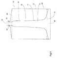
- Fig 4 gives a side-view of the housing assembly 10 to show the handle-side. This presents advantageous broadening of the handle 50 at the touch area making the profile flat. This improves the touch compared to cylindrical cross-sectional profile and gives more room for fingers between the body 20 and the channel 21, which is illustrated on Fig 2 .
- the open flow channel cross-sectional area remains to avoid increased gas flow resistance.
- the flattened profile is advantageously reformed to circular one to ensure leak-tight sealing to the breathing circuit.
- the seals 52 of the connectors may be part of the breathing circuit receptacle 53 or advantageously they are part of the housing assembly 10. In the latter the seals 52 become changed every time the housing assembly is changed thus ensuring the leak-tight connection.
- the second opening 39 at the top of open flow channel 21 is made flexibly moveable in relation to the first opening 38 at the top of the body 20.
- Fig 3 presents as top view an example of the elastic element 45 such as an intermediate wall that at the same time provides flexibility between the mutual distance of the body 20 and handle 50 for firm touch of the housing assembly.
- the elastic element 45 is made to comprise wave-formed structures that allow at the same time firm mounting and variability in mutual distance between the first opening 38 and the second opening 39.
Landscapes
- Health & Medical Sciences (AREA)
- Anesthesiology (AREA)
- Heart & Thoracic Surgery (AREA)
- Engineering & Computer Science (AREA)
- Pulmonology (AREA)
- Biomedical Technology (AREA)
- Emergency Medicine (AREA)
- Hematology (AREA)
- Life Sciences & Earth Sciences (AREA)
- Animal Behavior & Ethology (AREA)
- General Health & Medical Sciences (AREA)
- Public Health (AREA)
- Veterinary Medicine (AREA)
- Respiratory Apparatuses And Protective Means (AREA)
Claims (13)
- Ensemble de boîtier pour une substance (23) éliminant un composant de gaz respiratoire non souhaité d'un écoulement de gaz respiratoire, comprenant :un corps (20) ayant un espace (22) pour recevoir ladite substance et ayant une première extrémité (27) et une seconde extrémité (28) qui est opposée à ladite première extrémité, en permettant l'écoulement du gaz respiratoire entre ces extrémités, une première paroi (25) entourant au moins une partie dudit espace et une première ouverture (38) en communication fluidique avec ladite première extrémité et avec l'extérieur dudit boîtier ;un canal (21) en communication fluidique avec ladite seconde extrémité, lequel canal comprend un passage (35) entouré au moins en partie par une seconde paroi (36) pour guider l'écoulement de gaz et une seconde ouverture (39) en communication fluidique avec ledit passage et avec l'extérieur dudit boîtier ;caractérisé en ce que ladite au moins une partie dudit canal est à même d'être séparée dudit corps pour permettre une variation en matière d'emplacement mutuel de ladite première ouverture et de ladite seconde ouverture et en ce que le canal est à même d'agir comme une poignée (50) pour le corps.
- Ensemble de boîtier selon la revendication 1, caractérisé en ce que ladite variation quant à l'emplacement mutuel de ladite première ouverture et de ladite seconde ouverture comprend un changement de la distance entre ladite première ouverture et ladite seconde ouverture, laquelle distance peut varier d'au moins ± 0,1 mm, plus spécifiquement d'au moins ± 0,3 mm et de manière bien plus spécifique d'au moins ± 0,5 mm.
- Ensemble de boîtier selon la revendication 1, caractérisé en ce que, depuis l'une de ladite première ouverture et de ladite seconde ouverture, le gaz est à même de s'écouler vers ledit espace et l'ouverture restante de ladite première ouverture et de ladite seconde ouverture est destinée à éliminer le gaz dudit espace.
- Ensemble de boîtier selon la revendication 1, caractérisé en ce que ladite première ouverture et ladite seconde ouverture s'ouvrent dans la même direction.
- Ensemble de boîtier selon la revendication 1, caractérisé en ce que ledit boîtier comprend également un élément élastique (45) entre ladite première ouverture et ladite seconde ouverture.
- Ensemble de boîtier selon la revendication 5, caractérisé en ce que ledit élément élastique est à même de raccorder ladite seconde paroi à ladite première paroi.
- Ensemble de boîtier selon la revendication 5 ou la revendication 6, caractérisé en ce que ledit élément élastique est une paroi intermédiaire entre ladite seconde paroi et ladite première paroi.
- Ensemble de boîtier selon la revendication 1, caractérisé en ce qu'au moins une partie de l'un ou l'autre dudit canal et dudit corps comprend ledit élément élastique qui permet une flexion entraînant une variation entre les emplacements mutuels de ladite première ouverture et de ladite seconde ouverture.
- Ensemble de boîtier selon la revendication 1, caractérisé en ce que ladite première ouverture et ladite seconde ouverture sont parallèles.
- Ensemble de boîtier selon la revendication 1, caractérisé en ce qu'un espace d'un doigt (51) est ménagé entre ledit canal et ledit corps.
- Aménagement destiné à ventiler les poumons d'un sujet, comprenant :un ventilateur (3) pour fournir un gaz respiratoire pour une inspiration et recevoir un gaz respiratoire pour une expiration ;un mélangeur de gaz (5) pour fournir un gaz frais pour la respiration du sujet ; etun circuit respiratoire (7) pour raccorder les poumons (2) du sujet, ledit ventilateur et ledit mélangeur de gaz, ledit circuit respiratoire comprenant une branche d'inspiration (8) fournissant un gaz d'inspiration comprenant le gaz frais pour la respiration du sujet ; une branche d'expiration (9) pour décharger un gaz d'expiration ; et un ensemble de boîtier (10) selon la revendication 1.
- Aménagement selon la revendication 11, caractérisé en ce que ladite première ouverture et ladite seconde ouverture, qui sont à même d'être en communication fluidique avec l'extérieur du boîtier, sont à même de se trouver en communication fluidique avec ledit circuit respiratoire et ladite première ouverture et ladite seconde ouverture s'ouvrent dans la même direction.
- Ensemble de boîtier selon la revendication 11, caractérisé en ce que ladite variation quant à l'emplacement mutuel de ladite première ouverture et de ladite seconde ouverture comprend un changement de distance horizontale entre ladite première ouverture et ladite seconde ouverture.
Priority Applications (1)
| Application Number | Priority Date | Filing Date | Title |
|---|---|---|---|
| EP11186276.9A EP2586482B1 (fr) | 2011-10-24 | 2011-10-24 | Ensemble de boîtier avec une substance pour éliminer d'un composant indésirable du gaz respiratoire d'un flux de gaz respiratoire et agencement pour ventiler les poumons d'un sujet |
Applications Claiming Priority (1)
| Application Number | Priority Date | Filing Date | Title |
|---|---|---|---|
| EP11186276.9A EP2586482B1 (fr) | 2011-10-24 | 2011-10-24 | Ensemble de boîtier avec une substance pour éliminer d'un composant indésirable du gaz respiratoire d'un flux de gaz respiratoire et agencement pour ventiler les poumons d'un sujet |
Publications (2)
| Publication Number | Publication Date |
|---|---|
| EP2586482A1 EP2586482A1 (fr) | 2013-05-01 |
| EP2586482B1 true EP2586482B1 (fr) | 2016-02-10 |
Family
ID=44862647
Family Applications (1)
| Application Number | Title | Priority Date | Filing Date |
|---|---|---|---|
| EP11186276.9A Not-in-force EP2586482B1 (fr) | 2011-10-24 | 2011-10-24 | Ensemble de boîtier avec une substance pour éliminer d'un composant indésirable du gaz respiratoire d'un flux de gaz respiratoire et agencement pour ventiler les poumons d'un sujet |
Country Status (1)
| Country | Link |
|---|---|
| EP (1) | EP2586482B1 (fr) |
Family Cites Families (2)
| Publication number | Priority date | Publication date | Assignee | Title |
|---|---|---|---|---|
| CA668081A (en) * | 1963-08-06 | Air Reduction Company | Carbon dioxide absorber | |
| US6619289B1 (en) * | 2001-02-09 | 2003-09-16 | Datex-Ohmeda, Inc. | Carbon dioxide absorber canister with breathing gas moisture sump |
-
2011
- 2011-10-24 EP EP11186276.9A patent/EP2586482B1/fr not_active Not-in-force
Also Published As
| Publication number | Publication date |
|---|---|
| EP2586482A1 (fr) | 2013-05-01 |
Similar Documents
| Publication | Publication Date | Title |
|---|---|---|
| US8186347B2 (en) | Patient breathing system | |
| US20180169369A1 (en) | Oxygen rebreathing apparatus and method for using the same | |
| CN205924633U (zh) | 一种简易的麻醉呼吸管路 | |
| US9138551B2 (en) | Ventilator apparatus | |
| RU2766734C2 (ru) | Устройство для седации | |
| EP3912665B1 (fr) | Dispositif de ventilation non invasif et ensemble de recirculation | |
| US20160045703A1 (en) | Arrangement for guiding expired respiratory gas flow | |
| EP2586482B1 (fr) | Ensemble de boîtier avec une substance pour éliminer d'un composant indésirable du gaz respiratoire d'un flux de gaz respiratoire et agencement pour ventiler les poumons d'un sujet | |
| US8992672B2 (en) | Housing and housing assembly for substance removing an undesired respiratory gas component of a respiratory gas flow and an arrangement for ventilating lungs of a subject | |
| US8449661B2 (en) | Filter arrangement | |
| US9572952B2 (en) | Housing for solid, fluidal substance for removing an undesired respiratory gas component of a respiratory gas flow and an arrangement for ventilating lungs of a subject | |
| CN217067308U (zh) | 具有开放式呼吸气路的麻醉机 | |
| CN103239783A (zh) | 人工呼吸系统和用于人工呼吸系统的减少污染的接插系统 | |
| CN217286787U (zh) | 多用途麻醉机 | |
| ES1296246U (es) | Sistema de ventilación no invasiva | |
| CN207804731U (zh) | 可雾化给药的呼吸支持设备用呼吸系统 | |
| CN222172816U (zh) | 一种应用于医疗领域的一次性双通道呼吸过滤装置 | |
| GB2376185A (en) | Apparatus for administering oxygen to a subject | |
| McCarthy et al. | Anaesthetic breathing systems | |
| US20230226307A1 (en) | Absorption arrangement with a co2 absorber and a water trap and process for filtering out co2 | |
| CN220002662U (zh) | 一种麻醉面罩废气收集过滤装置 | |
| CN215690758U (zh) | 新型麻醉科用麻醉器 | |
| CN217286788U (zh) | 氧浓度可调的呼吸麻醉机 | |
| KR100770584B1 (ko) | 마취기에 사용되는 탄산가스 흡수 시스템 | |
| GB2512401A (en) | Arrangement and method for guiding expired respiratory gas flow through a housing assembly for removing undesirable respiratory gas component and breathing |
Legal Events
| Date | Code | Title | Description |
|---|---|---|---|
| PUAI | Public reference made under article 153(3) epc to a published international application that has entered the european phase |
Free format text: ORIGINAL CODE: 0009012 |
|
| AK | Designated contracting states |
Kind code of ref document: A1 Designated state(s): AL AT BE BG CH CY CZ DE DK EE ES FI FR GB GR HR HU IE IS IT LI LT LU LV MC MK MT NL NO PL PT RO RS SE SI SK SM TR |
|
| AX | Request for extension of the european patent |
Extension state: BA ME |
|
| 17P | Request for examination filed |
Effective date: 20131030 |
|
| 17Q | First examination report despatched |
Effective date: 20140314 |
|
| GRAP | Despatch of communication of intention to grant a patent |
Free format text: ORIGINAL CODE: EPIDOSNIGR1 |
|
| INTG | Intention to grant announced |
Effective date: 20150930 |
|
| GRAS | Grant fee paid |
Free format text: ORIGINAL CODE: EPIDOSNIGR3 |
|
| GRAA | (expected) grant |
Free format text: ORIGINAL CODE: 0009210 |
|
| AK | Designated contracting states |
Kind code of ref document: B1 Designated state(s): AL AT BE BG CH CY CZ DE DK EE ES FI FR GB GR HR HU IE IS IT LI LT LU LV MC MK MT NL NO PL PT RO RS SE SI SK SM TR |
|
| REG | Reference to a national code |
Ref country code: GB Ref legal event code: FG4D |
|
| REG | Reference to a national code |
Ref country code: AT Ref legal event code: REF Ref document number: 774343 Country of ref document: AT Kind code of ref document: T Effective date: 20160215 Ref country code: CH Ref legal event code: EP |
|
| REG | Reference to a national code |
Ref country code: IE Ref legal event code: FG4D |
|
| REG | Reference to a national code |
Ref country code: DE Ref legal event code: R096 Ref document number: 602011023197 Country of ref document: DE |
|
| REG | Reference to a national code |
Ref country code: LT Ref legal event code: MG4D |
|
| REG | Reference to a national code |
Ref country code: NL Ref legal event code: MP Effective date: 20160210 |
|
| REG | Reference to a national code |
Ref country code: AT Ref legal event code: MK05 Ref document number: 774343 Country of ref document: AT Kind code of ref document: T Effective date: 20160210 |
|
| PG25 | Lapsed in a contracting state [announced via postgrant information from national office to epo] |
Ref country code: ES Free format text: LAPSE BECAUSE OF FAILURE TO SUBMIT A TRANSLATION OF THE DESCRIPTION OR TO PAY THE FEE WITHIN THE PRESCRIBED TIME-LIMIT Effective date: 20160210 Ref country code: IT Free format text: LAPSE BECAUSE OF FAILURE TO SUBMIT A TRANSLATION OF THE DESCRIPTION OR TO PAY THE FEE WITHIN THE PRESCRIBED TIME-LIMIT Effective date: 20160210 Ref country code: HR Free format text: LAPSE BECAUSE OF FAILURE TO SUBMIT A TRANSLATION OF THE DESCRIPTION OR TO PAY THE FEE WITHIN THE PRESCRIBED TIME-LIMIT Effective date: 20160210 Ref country code: FI Free format text: LAPSE BECAUSE OF FAILURE TO SUBMIT A TRANSLATION OF THE DESCRIPTION OR TO PAY THE FEE WITHIN THE PRESCRIBED TIME-LIMIT Effective date: 20160210 Ref country code: GR Free format text: LAPSE BECAUSE OF FAILURE TO SUBMIT A TRANSLATION OF THE DESCRIPTION OR TO PAY THE FEE WITHIN THE PRESCRIBED TIME-LIMIT Effective date: 20160511 Ref country code: NO Free format text: LAPSE BECAUSE OF FAILURE TO SUBMIT A TRANSLATION OF THE DESCRIPTION OR TO PAY THE FEE WITHIN THE PRESCRIBED TIME-LIMIT Effective date: 20160510 |
|
| PG25 | Lapsed in a contracting state [announced via postgrant information from national office to epo] |
Ref country code: RS Free format text: LAPSE BECAUSE OF FAILURE TO SUBMIT A TRANSLATION OF THE DESCRIPTION OR TO PAY THE FEE WITHIN THE PRESCRIBED TIME-LIMIT Effective date: 20160210 Ref country code: PL Free format text: LAPSE BECAUSE OF FAILURE TO SUBMIT A TRANSLATION OF THE DESCRIPTION OR TO PAY THE FEE WITHIN THE PRESCRIBED TIME-LIMIT Effective date: 20160210 Ref country code: SE Free format text: LAPSE BECAUSE OF FAILURE TO SUBMIT A TRANSLATION OF THE DESCRIPTION OR TO PAY THE FEE WITHIN THE PRESCRIBED TIME-LIMIT Effective date: 20160210 Ref country code: IS Free format text: LAPSE BECAUSE OF FAILURE TO SUBMIT A TRANSLATION OF THE DESCRIPTION OR TO PAY THE FEE WITHIN THE PRESCRIBED TIME-LIMIT Effective date: 20160610 Ref country code: LT Free format text: LAPSE BECAUSE OF FAILURE TO SUBMIT A TRANSLATION OF THE DESCRIPTION OR TO PAY THE FEE WITHIN THE PRESCRIBED TIME-LIMIT Effective date: 20160210 Ref country code: NL Free format text: LAPSE BECAUSE OF FAILURE TO SUBMIT A TRANSLATION OF THE DESCRIPTION OR TO PAY THE FEE WITHIN THE PRESCRIBED TIME-LIMIT Effective date: 20160210 Ref country code: PT Free format text: LAPSE BECAUSE OF FAILURE TO SUBMIT A TRANSLATION OF THE DESCRIPTION OR TO PAY THE FEE WITHIN THE PRESCRIBED TIME-LIMIT Effective date: 20160613 Ref country code: LV Free format text: LAPSE BECAUSE OF FAILURE TO SUBMIT A TRANSLATION OF THE DESCRIPTION OR TO PAY THE FEE WITHIN THE PRESCRIBED TIME-LIMIT Effective date: 20160210 Ref country code: AT Free format text: LAPSE BECAUSE OF FAILURE TO SUBMIT A TRANSLATION OF THE DESCRIPTION OR TO PAY THE FEE WITHIN THE PRESCRIBED TIME-LIMIT Effective date: 20160210 |
|
| REG | Reference to a national code |
Ref country code: FR Ref legal event code: PLFP Year of fee payment: 6 |
|
| PG25 | Lapsed in a contracting state [announced via postgrant information from national office to epo] |
Ref country code: DK Free format text: LAPSE BECAUSE OF FAILURE TO SUBMIT A TRANSLATION OF THE DESCRIPTION OR TO PAY THE FEE WITHIN THE PRESCRIBED TIME-LIMIT Effective date: 20160210 Ref country code: EE Free format text: LAPSE BECAUSE OF FAILURE TO SUBMIT A TRANSLATION OF THE DESCRIPTION OR TO PAY THE FEE WITHIN THE PRESCRIBED TIME-LIMIT Effective date: 20160210 |
|
| REG | Reference to a national code |
Ref country code: DE Ref legal event code: R097 Ref document number: 602011023197 Country of ref document: DE |
|
| PG25 | Lapsed in a contracting state [announced via postgrant information from national office to epo] |
Ref country code: SM Free format text: LAPSE BECAUSE OF FAILURE TO SUBMIT A TRANSLATION OF THE DESCRIPTION OR TO PAY THE FEE WITHIN THE PRESCRIBED TIME-LIMIT Effective date: 20160210 Ref country code: SK Free format text: LAPSE BECAUSE OF FAILURE TO SUBMIT A TRANSLATION OF THE DESCRIPTION OR TO PAY THE FEE WITHIN THE PRESCRIBED TIME-LIMIT Effective date: 20160210 Ref country code: CZ Free format text: LAPSE BECAUSE OF FAILURE TO SUBMIT A TRANSLATION OF THE DESCRIPTION OR TO PAY THE FEE WITHIN THE PRESCRIBED TIME-LIMIT Effective date: 20160210 Ref country code: RO Free format text: LAPSE BECAUSE OF FAILURE TO SUBMIT A TRANSLATION OF THE DESCRIPTION OR TO PAY THE FEE WITHIN THE PRESCRIBED TIME-LIMIT Effective date: 20160210 |
|
| PLBE | No opposition filed within time limit |
Free format text: ORIGINAL CODE: 0009261 |
|
| STAA | Information on the status of an ep patent application or granted ep patent |
Free format text: STATUS: NO OPPOSITION FILED WITHIN TIME LIMIT |
|
| PG25 | Lapsed in a contracting state [announced via postgrant information from national office to epo] |
Ref country code: BE Free format text: LAPSE BECAUSE OF FAILURE TO SUBMIT A TRANSLATION OF THE DESCRIPTION OR TO PAY THE FEE WITHIN THE PRESCRIBED TIME-LIMIT Effective date: 20160210 |
|
| 26N | No opposition filed |
Effective date: 20161111 |
|
| PG25 | Lapsed in a contracting state [announced via postgrant information from national office to epo] |
Ref country code: BG Free format text: LAPSE BECAUSE OF FAILURE TO SUBMIT A TRANSLATION OF THE DESCRIPTION OR TO PAY THE FEE WITHIN THE PRESCRIBED TIME-LIMIT Effective date: 20160510 Ref country code: SI Free format text: LAPSE BECAUSE OF FAILURE TO SUBMIT A TRANSLATION OF THE DESCRIPTION OR TO PAY THE FEE WITHIN THE PRESCRIBED TIME-LIMIT Effective date: 20160210 |
|
| REG | Reference to a national code |
Ref country code: CH Ref legal event code: PL |
|
| GBPC | Gb: european patent ceased through non-payment of renewal fee |
Effective date: 20161024 |
|
| REG | Reference to a national code |
Ref country code: IE Ref legal event code: MM4A |
|
| PG25 | Lapsed in a contracting state [announced via postgrant information from national office to epo] |
Ref country code: GB Free format text: LAPSE BECAUSE OF NON-PAYMENT OF DUE FEES Effective date: 20161024 Ref country code: LI Free format text: LAPSE BECAUSE OF NON-PAYMENT OF DUE FEES Effective date: 20161031 Ref country code: CH Free format text: LAPSE BECAUSE OF NON-PAYMENT OF DUE FEES Effective date: 20161031 |
|
| PG25 | Lapsed in a contracting state [announced via postgrant information from national office to epo] |
Ref country code: LU Free format text: LAPSE BECAUSE OF NON-PAYMENT OF DUE FEES Effective date: 20161024 |
|
| REG | Reference to a national code |
Ref country code: FR Ref legal event code: PLFP Year of fee payment: 7 |
|
| PG25 | Lapsed in a contracting state [announced via postgrant information from national office to epo] |
Ref country code: IE Free format text: LAPSE BECAUSE OF NON-PAYMENT OF DUE FEES Effective date: 20161024 |
|
| PG25 | Lapsed in a contracting state [announced via postgrant information from national office to epo] |
Ref country code: CY Free format text: LAPSE BECAUSE OF FAILURE TO SUBMIT A TRANSLATION OF THE DESCRIPTION OR TO PAY THE FEE WITHIN THE PRESCRIBED TIME-LIMIT Effective date: 20160210 Ref country code: HU Free format text: LAPSE BECAUSE OF FAILURE TO SUBMIT A TRANSLATION OF THE DESCRIPTION OR TO PAY THE FEE WITHIN THE PRESCRIBED TIME-LIMIT; INVALID AB INITIO Effective date: 20111024 |
|
| PG25 | Lapsed in a contracting state [announced via postgrant information from national office to epo] |
Ref country code: MT Free format text: LAPSE BECAUSE OF NON-PAYMENT OF DUE FEES Effective date: 20161031 Ref country code: MC Free format text: LAPSE BECAUSE OF FAILURE TO SUBMIT A TRANSLATION OF THE DESCRIPTION OR TO PAY THE FEE WITHIN THE PRESCRIBED TIME-LIMIT Effective date: 20160210 Ref country code: TR Free format text: LAPSE BECAUSE OF FAILURE TO SUBMIT A TRANSLATION OF THE DESCRIPTION OR TO PAY THE FEE WITHIN THE PRESCRIBED TIME-LIMIT Effective date: 20160210 Ref country code: MK Free format text: LAPSE BECAUSE OF FAILURE TO SUBMIT A TRANSLATION OF THE DESCRIPTION OR TO PAY THE FEE WITHIN THE PRESCRIBED TIME-LIMIT Effective date: 20160210 |
|
| REG | Reference to a national code |
Ref country code: FR Ref legal event code: PLFP Year of fee payment: 8 |
|
| PG25 | Lapsed in a contracting state [announced via postgrant information from national office to epo] |
Ref country code: AL Free format text: LAPSE BECAUSE OF FAILURE TO SUBMIT A TRANSLATION OF THE DESCRIPTION OR TO PAY THE FEE WITHIN THE PRESCRIBED TIME-LIMIT Effective date: 20160210 |
|
| PGFP | Annual fee paid to national office [announced via postgrant information from national office to epo] |
Ref country code: FR Payment date: 20220920 Year of fee payment: 12 |
|
| PGFP | Annual fee paid to national office [announced via postgrant information from national office to epo] |
Ref country code: DE Payment date: 20220616 Year of fee payment: 12 |
|
| P01 | Opt-out of the competence of the unified patent court (upc) registered |
Effective date: 20230528 |
|
| REG | Reference to a national code |
Ref country code: DE Ref legal event code: R119 Ref document number: 602011023197 Country of ref document: DE |
|
| PG25 | Lapsed in a contracting state [announced via postgrant information from national office to epo] |
Ref country code: FR Free format text: LAPSE BECAUSE OF NON-PAYMENT OF DUE FEES Effective date: 20231031 Ref country code: DE Free format text: LAPSE BECAUSE OF NON-PAYMENT OF DUE FEES Effective date: 20240501 |