EP2586516A1 - Systèmes et procédés permettant de traiter le dioxyde de carbone - Google Patents
Systèmes et procédés permettant de traiter le dioxyde de carbone Download PDFInfo
- Publication number
- EP2586516A1 EP2586516A1 EP12180675.6A EP12180675A EP2586516A1 EP 2586516 A1 EP2586516 A1 EP 2586516A1 EP 12180675 A EP12180675 A EP 12180675A EP 2586516 A1 EP2586516 A1 EP 2586516A1
- Authority
- EP
- European Patent Office
- Prior art keywords
- heat exchange
- solid
- assembly
- housing
- exchange assembly
- Prior art date
- Legal status (The legal status is an assumption and is not a legal conclusion. Google has not performed a legal analysis and makes no representation as to the accuracy of the status listed.)
- Granted
Links
- CURLTUGMZLYLDI-UHFFFAOYSA-N Carbon dioxide Chemical compound O=C=O CURLTUGMZLYLDI-UHFFFAOYSA-N 0.000 title claims abstract description 252
- 229910002092 carbon dioxide Inorganic materials 0.000 title claims abstract description 233
- 239000001569 carbon dioxide Substances 0.000 title claims abstract description 226
- 238000000034 method Methods 0.000 title claims description 20
- 239000007787 solid Substances 0.000 claims abstract description 109
- 239000003546 flue gas Substances 0.000 claims abstract description 89
- 239000007788 liquid Substances 0.000 claims abstract description 49
- UGFAIRIUMAVXCW-UHFFFAOYSA-N Carbon monoxide Chemical compound [O+]#[C-] UGFAIRIUMAVXCW-UHFFFAOYSA-N 0.000 claims abstract description 40
- 239000012530 fluid Substances 0.000 claims abstract description 34
- 238000005057 refrigeration Methods 0.000 claims abstract description 24
- 238000001816 cooling Methods 0.000 claims description 58
- 239000007789 gas Substances 0.000 claims description 32
- 230000005465 channeling Effects 0.000 claims description 16
- 230000009919 sequestration Effects 0.000 claims description 6
- 238000000859 sublimation Methods 0.000 claims description 6
- 230000005484 gravity Effects 0.000 claims description 4
- 238000010248 power generation Methods 0.000 description 16
- 239000000446 fuel Substances 0.000 description 12
- 238000002485 combustion reaction Methods 0.000 description 6
- IJGRMHOSHXDMSA-UHFFFAOYSA-N Atomic nitrogen Chemical compound N#N IJGRMHOSHXDMSA-UHFFFAOYSA-N 0.000 description 5
- 239000007791 liquid phase Substances 0.000 description 4
- 239000000203 mixture Substances 0.000 description 4
- 239000000567 combustion gas Substances 0.000 description 3
- OKTJSMMVPCPJKN-UHFFFAOYSA-N Carbon Chemical compound [C] OKTJSMMVPCPJKN-UHFFFAOYSA-N 0.000 description 2
- ZAMOUSCENKQFHK-UHFFFAOYSA-N Chlorine atom Chemical compound [Cl] ZAMOUSCENKQFHK-UHFFFAOYSA-N 0.000 description 2
- BUGBHKTXTAQXES-UHFFFAOYSA-N Selenium Chemical compound [Se] BUGBHKTXTAQXES-UHFFFAOYSA-N 0.000 description 2
- NINIDFKCEFEMDL-UHFFFAOYSA-N Sulfur Chemical compound [S] NINIDFKCEFEMDL-UHFFFAOYSA-N 0.000 description 2
- 229910052785 arsenic Inorganic materials 0.000 description 2
- RQNWIZPPADIBDY-UHFFFAOYSA-N arsenic atom Chemical compound [As] RQNWIZPPADIBDY-UHFFFAOYSA-N 0.000 description 2
- 229910052799 carbon Inorganic materials 0.000 description 2
- 229910002091 carbon monoxide Inorganic materials 0.000 description 2
- 229910052801 chlorine Inorganic materials 0.000 description 2
- 239000000460 chlorine Substances 0.000 description 2
- 239000010881 fly ash Substances 0.000 description 2
- -1 for example Substances 0.000 description 2
- 238000010438 heat treatment Methods 0.000 description 2
- 229910052739 hydrogen Inorganic materials 0.000 description 2
- 239000001257 hydrogen Substances 0.000 description 2
- 125000004435 hydrogen atom Chemical class [H]* 0.000 description 2
- QSHDDOUJBYECFT-UHFFFAOYSA-N mercury Chemical compound [Hg] QSHDDOUJBYECFT-UHFFFAOYSA-N 0.000 description 2
- 229910052753 mercury Inorganic materials 0.000 description 2
- VNWKTOKETHGBQD-UHFFFAOYSA-N methane Chemical compound C VNWKTOKETHGBQD-UHFFFAOYSA-N 0.000 description 2
- 229910052757 nitrogen Inorganic materials 0.000 description 2
- 229910052711 selenium Inorganic materials 0.000 description 2
- 239000011669 selenium Substances 0.000 description 2
- 239000011593 sulfur Substances 0.000 description 2
- 229910052717 sulfur Inorganic materials 0.000 description 2
- XLYOFNOQVPJJNP-UHFFFAOYSA-N water Substances O XLYOFNOQVPJJNP-UHFFFAOYSA-N 0.000 description 2
- 229910001868 water Inorganic materials 0.000 description 2
- 239000002028 Biomass Substances 0.000 description 1
- 239000003245 coal Substances 0.000 description 1
- 238000004891 communication Methods 0.000 description 1
- 230000008021 deposition Effects 0.000 description 1
- 230000006870 function Effects 0.000 description 1
- 239000003345 natural gas Substances 0.000 description 1
- 239000003921 oil Substances 0.000 description 1
- 238000011084 recovery Methods 0.000 description 1
- 239000007790 solid phase Substances 0.000 description 1
- 239000002699 waste material Substances 0.000 description 1
Images




Classifications
-
- F—MECHANICAL ENGINEERING; LIGHTING; HEATING; WEAPONS; BLASTING
- F28—HEAT EXCHANGE IN GENERAL
- F28D—HEAT-EXCHANGE APPARATUS, NOT PROVIDED FOR IN ANOTHER SUBCLASS, IN WHICH THE HEAT-EXCHANGE MEDIA DO NOT COME INTO DIRECT CONTACT
- F28D1/00—Heat-exchange apparatus having stationary conduit assemblies for one heat-exchange medium only, the media being in contact with different sides of the conduit wall, in which the other heat-exchange medium is a large body of fluid, e.g. domestic or motor car radiators
- F28D1/02—Heat-exchange apparatus having stationary conduit assemblies for one heat-exchange medium only, the media being in contact with different sides of the conduit wall, in which the other heat-exchange medium is a large body of fluid, e.g. domestic or motor car radiators with heat-exchange conduits immersed in the body of fluid
- F28D1/04—Heat-exchange apparatus having stationary conduit assemblies for one heat-exchange medium only, the media being in contact with different sides of the conduit wall, in which the other heat-exchange medium is a large body of fluid, e.g. domestic or motor car radiators with heat-exchange conduits immersed in the body of fluid with tubular conduits
-
- B—PERFORMING OPERATIONS; TRANSPORTING
- B01—PHYSICAL OR CHEMICAL PROCESSES OR APPARATUS IN GENERAL
- B01D—SEPARATION
- B01D53/00—Separation of gases or vapours; Recovering vapours of volatile solvents from gases; Chemical or biological purification of waste gases, e.g. engine exhaust gases, smoke, fumes, flue gases, aerosols
- B01D53/002—Separation of gases or vapours; Recovering vapours of volatile solvents from gases; Chemical or biological purification of waste gases, e.g. engine exhaust gases, smoke, fumes, flue gases, aerosols by condensation
-
- F—MECHANICAL ENGINEERING; LIGHTING; HEATING; WEAPONS; BLASTING
- F28—HEAT EXCHANGE IN GENERAL
- F28D—HEAT-EXCHANGE APPARATUS, NOT PROVIDED FOR IN ANOTHER SUBCLASS, IN WHICH THE HEAT-EXCHANGE MEDIA DO NOT COME INTO DIRECT CONTACT
- F28D7/00—Heat-exchange apparatus having stationary tubular conduit assemblies for both heat-exchange media, the media being in contact with different sides of a conduit wall
- F28D7/08—Heat-exchange apparatus having stationary tubular conduit assemblies for both heat-exchange media, the media being in contact with different sides of a conduit wall the conduits being otherwise bent, e.g. in a serpentine or zig-zag
- F28D7/082—Heat-exchange apparatus having stationary tubular conduit assemblies for both heat-exchange media, the media being in contact with different sides of a conduit wall the conduits being otherwise bent, e.g. in a serpentine or zig-zag with serpentine or zig-zag configuration
-
- F—MECHANICAL ENGINEERING; LIGHTING; HEATING; WEAPONS; BLASTING
- F28—HEAT EXCHANGE IN GENERAL
- F28D—HEAT-EXCHANGE APPARATUS, NOT PROVIDED FOR IN ANOTHER SUBCLASS, IN WHICH THE HEAT-EXCHANGE MEDIA DO NOT COME INTO DIRECT CONTACT
- F28D7/00—Heat-exchange apparatus having stationary tubular conduit assemblies for both heat-exchange media, the media being in contact with different sides of a conduit wall
- F28D7/16—Heat-exchange apparatus having stationary tubular conduit assemblies for both heat-exchange media, the media being in contact with different sides of a conduit wall the conduits being arranged in parallel spaced relation
-
- B—PERFORMING OPERATIONS; TRANSPORTING
- B01—PHYSICAL OR CHEMICAL PROCESSES OR APPARATUS IN GENERAL
- B01D—SEPARATION
- B01D2257/00—Components to be removed
- B01D2257/50—Carbon oxides
- B01D2257/504—Carbon dioxide
-
- B—PERFORMING OPERATIONS; TRANSPORTING
- B01—PHYSICAL OR CHEMICAL PROCESSES OR APPARATUS IN GENERAL
- B01D—SEPARATION
- B01D2258/00—Sources of waste gases
- B01D2258/02—Other waste gases
- B01D2258/0283—Flue gases
-
- F—MECHANICAL ENGINEERING; LIGHTING; HEATING; WEAPONS; BLASTING
- F25—REFRIGERATION OR COOLING; COMBINED HEATING AND REFRIGERATION SYSTEMS; HEAT PUMP SYSTEMS; MANUFACTURE OR STORAGE OF ICE; LIQUEFACTION SOLIDIFICATION OF GASES
- F25J—LIQUEFACTION, SOLIDIFICATION OR SEPARATION OF GASES OR GASEOUS OR LIQUEFIED GASEOUS MIXTURES BY PRESSURE AND COLD TREATMENT OR BY BRINGING THEM INTO THE SUPERCRITICAL STATE
- F25J1/00—Processes or apparatus for liquefying or solidifying gases or gaseous mixtures
- F25J1/0002—Processes or apparatus for liquefying or solidifying gases or gaseous mixtures characterised by the fluid to be liquefied
- F25J1/0027—Oxides of carbon, e.g. CO2
-
- F—MECHANICAL ENGINEERING; LIGHTING; HEATING; WEAPONS; BLASTING
- F28—HEAT EXCHANGE IN GENERAL
- F28F—DETAILS OF HEAT-EXCHANGE AND HEAT-TRANSFER APPARATUS, OF GENERAL APPLICATION
- F28F1/00—Tubular elements; Assemblies of tubular elements
- F28F1/10—Tubular elements and assemblies thereof with means for increasing heat-transfer area, e.g. with fins, with projections, with recesses
- F28F1/12—Tubular elements and assemblies thereof with means for increasing heat-transfer area, e.g. with fins, with projections, with recesses the means being only outside the tubular element
-
- F—MECHANICAL ENGINEERING; LIGHTING; HEATING; WEAPONS; BLASTING
- F28—HEAT EXCHANGE IN GENERAL
- F28F—DETAILS OF HEAT-EXCHANGE AND HEAT-TRANSFER APPARATUS, OF GENERAL APPLICATION
- F28F1/00—Tubular elements; Assemblies of tubular elements
- F28F1/10—Tubular elements and assemblies thereof with means for increasing heat-transfer area, e.g. with fins, with projections, with recesses
- F28F1/12—Tubular elements and assemblies thereof with means for increasing heat-transfer area, e.g. with fins, with projections, with recesses the means being only outside the tubular element
- F28F1/24—Tubular elements and assemblies thereof with means for increasing heat-transfer area, e.g. with fins, with projections, with recesses the means being only outside the tubular element and extending transversely
Definitions
- the subject matter described herein relates generally to gas treatment systems and, more particularly, to gas treatment system for use in treating carbon dioxide (CO 2 ).
- At least some known power generation systems include a combustor and/or boiler to generate steam that is used in a steam turbine generator.
- a typical combustion process within a combustor or boiler for example, a flow of combustion gases, or flue gases, is produced.
- Known combustion gases contain combustion products including, but not limited to, carbon, fly ash, carbon dioxide, carbon monoxide, water, hydrogen, nitrogen, sulfur, chlorine, arsenic, selenium, and/or mercury.
- At least some known power generation systems include a gas treatment system for use in reducing an amount of combustion products within the flue gases.
- gas treatment systems include a low-temperature cooling system for separating CO 2 from the flue gases. During operation, the low-temperature cooling system cools a flue gas stream to form solid CO 2 from gaseous CO 2 suspended within the flue gas stream.
- at least some known gas treatment systems include a low-temperature solids pump for use in transporting the solid CO 2 from the low-temperature cooling system to a CO 2 sequestration system for sequestration and deposition of the CO 2 . During operation, the low-temperature cooling system transfers a refrigeration value to the flue gas stream to form solid CO 2 .
- the low-temperature solids pump conveys the solid CO 2 from the cooling system
- at least some of the refrigeration value may be lost to heat generated from operation of the solids pump.
- the loss of refrigeration value through the solids pump increases the cost of operating the gas treatment system by increasing an amount of energy required to cool the flue gas stream.
- a heat exchange assembly for treating carbon dioxide (CO 2 ) is provided.
- the heat exchange assembly includes a housing that includes an inlet, an outlet, and an inner surface that defines a cavity extending between the inlet and the outlet.
- the housing is configured to receive solid CO 2 through the inlet.
- At least one heat exchange tube extends through the housing.
- the heat exchange tube is oriented to contact solid CO 2 to facilitate transferring heat from solid CO 2 to a heat exchanger fluid being channeled through the heat exchange tube to facilitate converting at least a portion of solid CO 2 into liquid CO 2 .
- the heat exchange assembly is configured to recover a refrigeration value from the solid CO 2 and transfer at least a portion of the recovered refrigeration value to a flue gas.
- a gas treatment system for use in treating carbon dioxide (CO 2 ) in a flue gas.
- the gas treatment system includes a cooling system coupled to a source of flue gas and configured to receive a flow of flue gas from the source.
- the cooling system is configured to cool gaseous CO 2 suspended within the flue gas to form solid CO 2 .
- a heat exchange assembly as described above is coupled to the cooling system for receiving a flow of solid CO 2 from the cooling system.
- a method of treating carbon dioxide (CO 2 ) includes channeling a flue gas containing CO 2 to a cooling system to cool the flue gas to form solid CO 2 , and channeling solid CO 2 to a heat exchanger assembly.
- the heat exchanger assembly includes a housing that is configured to receive solid CO 2 therein, and at least one heat exchange tube extending through the housing. A pressure within the housing is adjusted to maintain the housing pressure within a predefined range of pressures to prevent re-sublimation of solid CO 2 .
- a flow of heat exchange fluid is channeled through the at least one heat exchange tube to facilitate a transfer of heat from solid CO 2 to the heat exchange fluid to convert at least a portion of solid CO 2 into liquid CO 2 , and to recover a refrigeration value from the CO 2 . At least a portion of the recovered refrigeration value is transferred to the flue gas to facilitate cooling the flue gas.
- the exemplary systems and methods described herein overcome at least some disadvantages of known gas treatment systems by providing a gas treatment system that includes a heat exchange assembly that is configured to transfer heat from a heat exchange fluid to solid CO 2 to facilitate recovering a refrigeration value from solid CO 2 .
- the heat exchange assembly is configured to maintain CO 2 in solid-liquid phase equilibrium to enable the heat exchange assembly to transfer heat to solid CO 2 to facilitate forming liquid CO 2 for use in pre-cooling a flue gas.
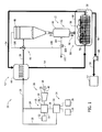
- FIG. 1 is a schematic view of an exemplary power generation system 10.
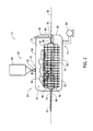
- FIG. 2 is a schematic view of an exemplary heat exchange assembly 12 that may be used with power generation system 10.
- power generation system 10 includes a combustor assembly 14, a steam generation assembly 16 downstream of combustor assembly 14, and a steam turbine engine 20 coupled to steam generation assembly 16.
- Combustor assembly 14 includes at least one combustor 22, a fuel supply system 24, and an air supply system 26.
- Fuel supply system 24 is coupled to combustor 22 for channeling a flow of fuel such as, for example, coal to combustor 22.
- fuel supply system 24 may channel any other suitable fuel, including but not limited to, oil, natural gas, biomass, waste, and/or any other fossil and/or renewable fuel that enables power generation system 10 to function as described herein.
- air supply system 26 is coupled to combustor 22 for channeling a flow of air to combustor 22.
- Combustor 22 is configured to receive a predetermined quantity of fuel and air from fuel supply system 24 and air supply system 26, respectively, and ignite the fuel/air mixture to generate combustion or flue gases.
- combustor 22 channels a flow of flue gases 28 to steam generation assembly 16 to generate steam that is channeled to steam turbine engine 20 for use in generating a power load.
- steam generation assembly 16 includes at least one heat recovery steam generator (HRSG) 30 that is coupled in flow communication with a boiler feedwater assembly 32.
- HRSG 30 receives a flow of boiler feedwater 33 from boiler feedwater assembly 32 to facilitate heating boiler feedwater 33 to generate steam.
- HRSG 30 also receives flue gases 28 from combustor assembly 14 to further heat boiler feedwater 33 to generate steam.
- HRSG 30 is configured to facilitate transferring heat from flue gases 28 to boiler feedwater 33 to generate steam, and channel steam 34 to steam turbine engine 20.
- Steam turbine engine 20 includes one or more steam turbines 36 that are rotatably coupled to a power generator 38 with a drive shaft 40.
- HRSG 30 discharges steam 34 towards steam turbine 36 wherein thermal energy in the steam is converted to mechanical rotational energy.
- Steam 34 imparts rotational energy to steam turbine 36 and to drive shaft 40, which subsequently drives power generator 38 to facilitate generating a power load.
- power generation system 10 includes a gas treatment system 42 that is downstream from combustor assembly 14 and steam generation assembly 16.
- Gas treatment system 42 is configured to receive flue gases 28 exhausted from combustor assembly 14 and/or steam generation assembly 16 to facilitate removing combustion products including, but not limited to, carbon, fly ash, carbon dioxide, carbon monoxide, water, hydrogen, nitrogen, sulfur, chlorine, arsenic, selenium, and/or mercury from the flue gases.
- gas treatment system 42 includes a flue gas pre-cooling system 44, a low-temperature cooling system 46 downstream of flue gas pre-cooling system 44, a CO 2 separator 48 downstream of cooling system 46, heat exchange assembly 12 downstream of cooling system 46, and a CO 2 utilization system 52 downstream of heat exchange assembly 12.
- Flue gases 28 including gaseous CO 2 and nitrogen (N 2 ) are channeled to flue gas pre-cooling system 44 from combustor assembly 14 and/or steam generation assembly 16.
- Flue gas pre-cooling system 44 facilitates a heat transfer from flue gases 28 to a heat exchange fluid 54 being channeled through flue gas pre-cooling system 44 to facilitate reducing a temperature of flue gases 28.
- Pre-cooling system 44 channels the cooled flue gases 28 to cooling system 46.
- Cooling system 46 is configured to treat flue gases 28 to cool gaseous CO 2 within flue gases 28 to form solid CO 2 .
- Cooling system 46 channels cooled flue gases 28 and solid CO 2 to CO 2 separator 48 to facilitate separating solid CO 2 and N 2 from flue gases 28.
- CO 2 separator 48 channels solid CO 2 56 to heat exchange assembly 12 to facilitate transferring heat from heat exchange fluid 54 to solid CO 2 56.
- heat exchange assembly 12 is configured to facilitate transferring of heat from solid CO 2 56 to heat exchange fluid 54 being channeled through heat exchange assembly 12 to facilitate converting solid CO 2 56 to liquid CO 2 58.
- heat exchange assembly 12 is configured to recover a refrigeration value from solid CO 2 56 and transfer at least a portion of the recovered refrigeration value to the flue gases 28 to facilitate cooling flue gases 28.
- heat exchange assembly 12 is configured to channel liquid CO 2 58 to CO 2 utilization system 52 for utilization of rich CO 2 .
- CO 2 utilization system 52 includes a sequestration system for sequestration of rich CO 2 .
- utilization system 52 may include any system configured to use CO 2 for any purpose.
- heat exchange assembly 12 is also configured to adjust a temperature and a pressure within heat exchange assembly 12 such that CO 2 within heat exchange assembly 12 is in solid-liquid phase equilibrium.
- Heat exchange assembly 12 includes a heat exchanger 60 and a lockhopper assembly 62.
- Lockhopper assembly 62 is coupled between heat exchanger 60 and CO 2 separator 48 for channeling solid CO 2 56 from CO 2 separator 48 to heat exchanger 60.
- Lockhopper assembly 62 includes a tank 64 that is configured to receive solid CO 2 56 from CO 2 separator 48, and a valve assembly 66 coupled between tank 64 and heat exchanger 60 to enable solid CO 2 56 to be selectively channeled to heat exchanger 60 from tank 64.
- Lockhopper assembly 62 is configured to adjust a pressure within tank 64 such that a pressure within tank 64 is within a range of pressures such that solid CO 2 56 remains in the solid phase.
- lockhopper assembly 62 is configured to enable solid CO 2 56 to be gravity fed from tank 64 into heat exchanger 60.
- lockhopper assembly 62 is configured to maintain an interior pressure equal to about 7 atm.
- Heat exchanger 60 includes a housing 68 and at least one heat exchange tube 70 that extends through housing 68.
- Housing 68 includes an inlet 72, an outlet 74, and an inner surface 76 that defines a cavity 78 extending between inlet 72 and outlet 74.
- Housing 68 is configured to maintain a pressure within cavity 78 within a predefined range of pressures to facilitate preventing re-sublimation of solid CO 2 56 to gaseous CO 2 within cavity 78.
- housing 68 is configured to maintain an internal pressure of about 7 atm.
- housing 68 is configured to maintain an internal pressure between about 1 atm to about 10 atm.
- lockhopper assembly 62 channels a flow of pressurized fluid to housing cavity 78 through valve assembly 66 to pressurize housing 68 to a predefined pressure.
- inner surface 76 includes an upper portion 80, and a lower portion 82 that extends below upper portion 80.
- Inlet 72 extends through upper portion 80 and is coupled to lockhopper assembly 62 for receiving solid CO 2 56 from lockhopper assembly 62.
- housing lower portion 82 is sized and shaped to contain liquid CO 2 58 therein.
- Outlet 74 extends through lower portion 82, and is coupled to CO 2 utilization system 52.
- heat exchange assembly 12 includes a liquid CO 2 pump 84 that is coupled between heat exchanger 60 and CO 2 utilization system 52 for channeling liquid CO 2 58 from lower portion 82 to CO 2 utilization system 52.
- heat exchange tube 70 extends though housing cavity 78, and is configured to channel a flow of heat exchange fluid 54 through housing cavity 78.
- Heat exchange tube 70 extends along a centerline axis 85 between a first end 86, and a second end 88.
- Heat exchange tube 70 is oriented within cavity 78 such that an outer surface 90 of heat exchange tube 70 contacts solid CO 2 56 to facilitate transferring heat from heat exchange fluid 54 to solid CO 2 56 to increase a temperature of solid CO 2 56 and facilitate converting at least a portion of solid CO 2 56 to liquid CO 2 58.
- Heat exchange assembly 12 also includes a plurality of fins 92 that extend outwardly from tube outer surface 90.
- Each fin 92 includes an outer surface 94 that is configured to contact solid CO 2 56 to facilitate transferring heat from heat exchange fluid 54 to solid CO 2 56 to facilitate forming liquid CO 2 58 from solid CO 2 56, and to cool heat exchange fluid 54 to recover a refrigeration value from solid CO 2 56.
- Each fin 92 is oriented within cavity 78 such that solid CO 2 56 is at least partially supported by heat exchange tube 70 within housing upper portion 80.
- each fin 92 is oriented to channel liquid CO 2 58 formed within cavity 78 from upper portion 80 to lower portion 82 such that liquid CO 2 58 is collected within a pool 96 formed within lower portion 82.
- each fin 92 is oriented substantially perpendicular to centerline axis 85.
- each fin 92 is at least partially submerged within liquid CO 2 58 to facilitate transferring heat from liquid CO 2 58 to heat exchange fluid 54.
- heat exchange tube 70 includes a plurality of pipes 98 that are each coupled to one or more fins 92.
- Each pipe 98 is oriented within cavity 78, and extends between first end 86 and second end 88.
- One or more pipes 98 are at least partially submerged within liquid CO 2 58 to facilitate transferring heat from liquid CO 2 58 to heat exchange fluid 54.
- combustor 22 receives a predefined quantity of fuel from fuel supply system 24, and receives a predefined quantity of air from air supply system 26.
- Combustor 22 injects the fuel into the air flow, ignites the fuel-air mixture to expand the fuel-air mixture through combustion, and generates high temperature flue gases.
- Combustor 22 channels flue gases 28 to HRSG 30 to facilitate generating steam from flue gases 28.
- boiler feedwater assembly 32 channels a flow of boiler feedwater 33 to HRSG 30.
- HRSG 30 transfers heat from flue gases 28 to boiler feedwater 33 to facilitate heating boiler feedwater 33 to generate steam 34.
- HRSG 30 discharges steam 34 towards steam turbine 36 wherein thermal energy in the steam is converted to mechanical rotational energy.
- HRSG 30 and/or combustor 22 discharge flue gases 28 toward gas treatment system 42 to facilitate treating carbon dioxide CO 2 suspended within flue gases 28.
- HRSG 30 and/or combustor 22 channel flue gases to pre-cooling system 44.
- Pre-cooling system 44 transfers heat from flue gases 28 to heat exchange fluid 54 to reduce a temperature of flue gases 28.
- Pre-cooling system 44 discharges flue gases 28 towards cooling system 46 to facilitate generating solid CO 2 from gaseous CO 2 suspended within flue gases 28.
- pre-cooling system 44 channels heat exchange fluid 54 towards heat exchange assembly 12.
- Cooling system 46 cools flue gases 28 to generate solid CO 2 and channels cooled flue gases 28 and solid CO 2 56 to CO 2 separator 48 to facilitate separating solid CO 2 and N 2 from flue gases 28.
- CO 2 separator 48 discharges solid CO 2 towards lockhopper assembly 62.
- CO 2 separator 48 channels a flow of CO 2 lean gas 100 that includes a mixture of CO 2 and N 2 to cooling system 46 and/or lockhopper assembly 62.
- CO 2 lean gas 100 discharged from CO 2 separator 48 is divided into a first sub-stream 102 and a second sub-stream 104.
- First sub-stream 102 is discharged to atmosphere.
- Second sub-stream 104 is compressed in a compressor 106 and channeled to lockhopper assembly 62 at a predefined pressure to facilitate adjusting a pressure within lockhopper assembly 62.
- Lockhopper assembly 62 channels solid CO 2 56 towards heat exchanger 60 to transfer heat from solid CO 2 56 to heat exchange fluid 54 being channeled through heat exchanger 60.
- Solid CO 2 56 is gravity fed to heat exchanger 60 to transfer heat from heat exchange fluid 54 to solid CO 2 56 to convert at least of portion of solid CO 2 58 to liquid CO 2 58, and to cool heat exchange fluid 54 to recover a refrigeration value from solid CO 2 56.
- Heat exchanger 60 discharges liquid CO 2 58 to CO 2 utilization system 52.
- heat exchanger 60 channels heat exchange fluid 54 towards pre-cooling system 44 for use in cooling flue gases 28.
- lockhopper assembly 62 and heat exchanger 60 each include an internal pressure equal to about 7 atm to facilitate preventing re-sublimation of solid CO 2 56 to gaseous CO 2 within cavity 78, and to maintain CO 2 in solid-liquid phase equilibrium.
- Lockhopper assembly 62 channels solid CO 2 56 having a temperature equal to about -102°C towards heat exchanger 60.
- Heat exchange fluid 54 is channeled into heat exchanger 60 includes a temperature equal to about -51°C.
- Liquid CO 2 58 discharged from heat exchanger 60 includes a fluid temperature equal to about -51°C.
- Heat exchange fluid 54 discharged from heat exchanger 60 includes a fluid temperature equal to about - 80°C.
- FIGS. 3-4 are schematic views of alternative embodiments of heat exchange assembly 12. Identical components shown in FIGS. 3-4 are labeled with the same reference numbers used in FIG. 2 .
- heat exchange tube 70 extends between a first section 108 and a second section 110.
- First section 108 is oriented within lower portion 82 such that first section 108 is at least partially submerged within liquid CO 2 58.
- Second section 110 is oriented within upper portion 80, and is configured to support solid CO 2 56 such that solid CO 2 56 is oriented above liquid CO 2 pool 96.
- Fins 92 are coupled to heat exchange tube 70 and are oriented obliquely with respect to centerline axis 85 to facilitate channeling liquid CO 2 58 from upper portion 80 to lower portion 82.
- One or more fins 92 are coupled to tube first section 108, and are at least partially submerged within liquid CO 2 58.
- each fin 92 is coupled to second section 110 of heat exchange tube 70 such that each fm 92 is oriented within upper portion 80.
- Each fin 92 is oriented with respect to an adjacent fin 92 such that a plurality of openings 112 are defined between adjacent fins 92.
- Each opening 112 is sized and shaped to channel liquid CO 2 58 from upper portion 80 to lower portion 82.
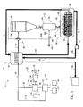
- FIG. 5 is another embodiment of power generation system 10. Identical components shown in FIG. 5 are labeled with the same reference numbers used in FIG. 1 .
- heat exchanger 60 channels cold liquid CO 2 58 to flue gas pre-cooling system 44 for use in pre-cooling flue gases 28.
- liquid CO 2 pump 84 channels liquid CO 2 58 from heat exchanger 60 to flue gas pre-cooling system 44.
- flue gas pre-cooling system 44 channels liquid CO 2 58 to CO 2 utilization system 52.
- liquid CO 2 pump 84 is configured to channel liquid CO 2 58 through flue gas pre-cooling system 44, and to CO 2 utilization system 52.
- FIG. 6 is an alternative embodiment of power generation system 10. Identical components shown in FIG. 6 are labeled with the same reference numbers used in FIG. 1 .
- power generation system 10 includes a top cycle or gas turbine engine assembly 114 and a bottom cycle or steam turbine engine 20.
- Gas turbine engine assembly 114 includes a compressor 116, a combustor 118 downstream of compressor 116, and a turbine 120 downstream of combustor 118 and powered by gases discharged from combustor 118.
- Turbine 120 drives an electrical generator 122.
- turbine 120 discharges flue gases 28 to HRSG 30 for generating steam from flue gases 28.
- heat exchanger 60 is coupled downstream of pre-cooling system 44 for receiving a flow of flue gases 28 from pre-cooling system 44.
- HRSG 30 and/or turbine 120 discharge flue gases 28 to pre-cooling system 44 to transfer heat from flue gases 28 to liquid CO 2 58.
- Pre-cooling system 44 channels flue gases 28 to heat exchanger 60 to transfer heat from flue gases 28 to solid CO 2 56 to form liquid CO 2 58 from solid CO 2 56 to facilitate cooling flue gases 28, and to recover a refrigeration value from solid CO 2 56.
- Heat exchanger 60 channels cooled flue gases 28 to cooling system 46 to cool flue gases 28 to form solid CO 2 from gaseous CO 2 suspended within flue gases 28.
- Cooling system 46 channels solid CO 2 and flue gases 28 to CO 2 separator 48 to separate solid CO 2 from flue gases 28, and discharge solid CO 2 to lockhopper assembly 62.
- Lockhopper assembly 62 discharges solid CO 2 56 to heat exchanger 60 to transfer heat from solid CO 2 56 to flue gases 28 being channeled through heat exchanger 60, and to form liquid CO 2 58 from solid CO 2 56.
- Heat exchanger 60 channels liquid CO 2 58 to pre-cooling system 44 to facilitate transferring heat from flue gases 28 to liquid CO 2 58.
- pre-cooling system 44 channels liquid CO 2 58 to CO 2 utilization system 52.
- FIG. 7 is a flow chart of an exemplary method 200 that may be used to treat CO 2 that is generated during an operation of power generation system 10.
- method 200 includes channeling 202 solid CO 2 from lockhopper assembly 62 to heat exchange assembly 12, and channeling 204 a flow of heat exchange fluid 54 through heat exchange tube 70 to facilitate a transfer of heat from solid CO 2 to heat exchange fluid 54 to form liquid CO 2 from solid CO 2 , and to recover a refrigeration value from solid CO 2 and liquid CO 2 .
- Method 200 also includes adjusting 206 a pressure within housing 68 to maintain a housing pressure within a predefined range of pressures to prevent re-sublimation of solid CO 2 to gaseous CO 2 .
- Heat exchange fluid 54 is channeled 208 from heat exchange assembly 12 to pre-cooling system 44 to pre-cool flue gases 28.
- Liquid CO 2 is channeled 210 from heat exchange assembly 12 to a CO 2 utilization system 52 to facilitate utilization of rich CO 2 .
- the above-described systems and methods overcome at least some disadvantages of known gas treatment systems by providing a gas treatment system that includes a heat exchange assembly configured to transfer heat from a heat exchange fluid to solid CO 2 to facilitate recovering a refrigeration value from solid CO 2 .
- the gas treatment system includes a heat exchange assembly that is configured to maintain CO 2 in solid-liquid phase equilibrium to enable the heat exchange assembly to transfer heat from solid CO 2 to a heat exchange fluid to facilitate forming liquid CO 2 for use in pre-cooling a flue gas.
- systems and methods for treating carbon dioxide are described above in detail.
- the systems and methods are not limited to the specific embodiments described herein, but rather, components of systems and/or steps of the method may be utilized independently and separately from other components and/or steps described herein.
- the systems and method may also be used in combination with other gas treatment systems and methods, and are not limited to practice with only the gas treatment system as described herein. Rather, the exemplary embodiment can be implemented and utilized in connection with many other gas treatment system applications.
Landscapes
- Engineering & Computer Science (AREA)
- General Engineering & Computer Science (AREA)
- Physics & Mathematics (AREA)
- Thermal Sciences (AREA)
- Mechanical Engineering (AREA)
- Chemical & Material Sciences (AREA)
- Chemical Kinetics & Catalysis (AREA)
- Analytical Chemistry (AREA)
- General Chemical & Material Sciences (AREA)
- Oil, Petroleum & Natural Gas (AREA)
- Treating Waste Gases (AREA)
- Carbon And Carbon Compounds (AREA)
- Gas Separation By Absorption (AREA)
Applications Claiming Priority (1)
| Application Number | Priority Date | Filing Date | Title |
|---|---|---|---|
| US13/285,375 US20130104595A1 (en) | 2011-10-31 | 2011-10-31 | Systems and methods for treating carbon dioxide |
Publications (2)
| Publication Number | Publication Date |
|---|---|
| EP2586516A1 true EP2586516A1 (fr) | 2013-05-01 |
| EP2586516B1 EP2586516B1 (fr) | 2017-06-28 |
Family
ID=46939484
Family Applications (1)
| Application Number | Title | Priority Date | Filing Date |
|---|---|---|---|
| EP12180675.6A Not-in-force EP2586516B1 (fr) | 2011-10-31 | 2012-08-16 | Systèmes et procédés permettant de traiter le dioxyde de carbone |
Country Status (5)
| Country | Link |
|---|---|
| US (2) | US20130104595A1 (fr) |
| EP (1) | EP2586516B1 (fr) |
| JP (1) | JP6132491B2 (fr) |
| CN (1) | CN103090697B (fr) |
| RU (1) | RU2601679C2 (fr) |
Cited By (1)
| Publication number | Priority date | Publication date | Assignee | Title |
|---|---|---|---|---|
| WO2022018201A1 (fr) * | 2020-07-22 | 2022-01-27 | Revcoo | Système de captation de dioxyde de carbone par atomisation d'azote liquide |
Families Citing this family (8)
| Publication number | Priority date | Publication date | Assignee | Title |
|---|---|---|---|---|
| CN109386735B (zh) * | 2017-08-08 | 2020-10-16 | 中国石油化工股份有限公司 | 一种用于bog和二氧化碳零排放的联合处理系统及工艺 |
| CN107677044B (zh) * | 2017-08-28 | 2020-06-09 | 浙江大学 | 一种采用低温凝华法的富氧燃烧尾气处理系统 |
| US20190170441A1 (en) * | 2017-12-05 | 2019-06-06 | Larry Baxter | Pressure-Regulated Melting of Solids with Warm Fluids |
| US20190170440A1 (en) * | 2017-12-05 | 2019-06-06 | Larry Baxter | Pressure-Regulated Melting of Solids |
| CN108777332B (zh) * | 2018-05-31 | 2020-07-24 | 安徽南都华铂新材料科技有限公司 | 一种利用干冰对废旧锂离子电池进行预处理的方法 |
| EP3948125B1 (fr) * | 2019-03-29 | 2026-02-25 | FrostCarbon, Inc. | Système et procédé de séparation et de liquéfaction du co2 |
| CN113842662B (zh) * | 2020-10-19 | 2022-09-13 | 湖南医药学院 | 一种樟脑合成用升华设备 |
| JP2025532326A (ja) * | 2022-10-06 | 2025-09-29 | アトウッド,マシュー | 気体の極低温分離のための新規表面および形状を利用した装置、方法およびシステム |
Citations (5)
| Publication number | Priority date | Publication date | Assignee | Title |
|---|---|---|---|---|
| US2738658A (en) * | 1952-12-24 | 1956-03-20 | Air Reduction | Separation of gas by solidification |
| DE19940371A1 (de) * | 1999-08-25 | 2001-03-01 | Messer Griesheim Gmbh | Verfahren und Vorrichtung zur Gewinnung von Kohlendioxid aus Abgasen |
| US20040148961A1 (en) * | 2001-01-30 | 2004-08-05 | Denis Clodic | Method and system for extracting carbon dioxide by anti-sublimation for storage thereof |
| WO2011018577A2 (fr) * | 2009-08-13 | 2011-02-17 | Association Pour La Recherche Et Le Developpement De Methodes Et Processus Industriels "Armines" | Procede et systeme ameliores pour l'extraction d'une substance par antisublimation et fusion |
| FR2949553A1 (fr) * | 2009-09-02 | 2011-03-04 | Air Liquide | Procede de production d'au moins un gaz pauvre en co2 et d'un ou plusieurs fluides riches en co2 |
Family Cites Families (5)
| Publication number | Priority date | Publication date | Assignee | Title |
|---|---|---|---|---|
| US2496185A (en) * | 1946-11-07 | 1950-01-31 | Cardox Corp | Method and apparatus for charging vessels with solid carbon dioxide |
| US6003332A (en) * | 1997-06-02 | 1999-12-21 | Cyrogenic Applications F, Inc. | Process and system for producing high-density pellets from a gaseous medium |
| JP2000317302A (ja) * | 1999-05-10 | 2000-11-21 | Chugoku Electric Power Co Inc:The | 燃焼排ガスの処理方法及び装置 |
| JP2005279640A (ja) * | 2004-03-02 | 2005-10-13 | Chugoku Electric Power Co Inc:The | 排ガスの処理方法及びシステム |
| AU2007337482A1 (en) * | 2006-12-25 | 2008-07-03 | Jfe Engineering Corporation | Process and apparatus for producing clathrate hydrate slurry and method of operating the production apparatus |
-
2011
- 2011-10-31 US US13/285,375 patent/US20130104595A1/en not_active Abandoned
-
2012
- 2012-08-16 EP EP12180675.6A patent/EP2586516B1/fr not_active Not-in-force
- 2012-08-28 JP JP2012187110A patent/JP6132491B2/ja not_active Expired - Fee Related
- 2012-08-30 RU RU2012136926/06A patent/RU2601679C2/ru not_active IP Right Cessation
- 2012-08-31 CN CN201210317485.8A patent/CN103090697B/zh not_active Expired - Fee Related
-
2014
- 2014-09-16 US US14/487,985 patent/US20150000333A1/en not_active Abandoned
Patent Citations (5)
| Publication number | Priority date | Publication date | Assignee | Title |
|---|---|---|---|---|
| US2738658A (en) * | 1952-12-24 | 1956-03-20 | Air Reduction | Separation of gas by solidification |
| DE19940371A1 (de) * | 1999-08-25 | 2001-03-01 | Messer Griesheim Gmbh | Verfahren und Vorrichtung zur Gewinnung von Kohlendioxid aus Abgasen |
| US20040148961A1 (en) * | 2001-01-30 | 2004-08-05 | Denis Clodic | Method and system for extracting carbon dioxide by anti-sublimation for storage thereof |
| WO2011018577A2 (fr) * | 2009-08-13 | 2011-02-17 | Association Pour La Recherche Et Le Developpement De Methodes Et Processus Industriels "Armines" | Procede et systeme ameliores pour l'extraction d'une substance par antisublimation et fusion |
| FR2949553A1 (fr) * | 2009-09-02 | 2011-03-04 | Air Liquide | Procede de production d'au moins un gaz pauvre en co2 et d'un ou plusieurs fluides riches en co2 |
Cited By (2)
| Publication number | Priority date | Publication date | Assignee | Title |
|---|---|---|---|---|
| WO2022018201A1 (fr) * | 2020-07-22 | 2022-01-27 | Revcoo | Système de captation de dioxyde de carbone par atomisation d'azote liquide |
| FR3112697A1 (fr) * | 2020-07-22 | 2022-01-28 | Revcoo | Système de captation de dioxyde de carbone par atomisation d’azote liquide. |
Also Published As
| Publication number | Publication date |
|---|---|
| JP2013096695A (ja) | 2013-05-20 |
| US20150000333A1 (en) | 2015-01-01 |
| CN103090697B (zh) | 2016-08-24 |
| RU2012136926A (ru) | 2014-03-10 |
| US20130104595A1 (en) | 2013-05-02 |
| CN103090697A (zh) | 2013-05-08 |
| RU2601679C2 (ru) | 2016-11-10 |
| JP6132491B2 (ja) | 2017-05-24 |
| EP2586516B1 (fr) | 2017-06-28 |
Similar Documents
| Publication | Publication Date | Title |
|---|---|---|
| EP2586516B1 (fr) | Systèmes et procédés permettant de traiter le dioxyde de carbone | |
| ES2508173T3 (es) | Sistema y método para generación de energía con alta eficiencia utilizando un fluido de trabajo de nitrógeno gaseoso | |
| US7726114B2 (en) | Integrated combustor-heat exchanger and systems for power generation using the same | |
| AU2011271632B2 (en) | Low emission triple-cycle power generation systems and methods | |
| US6877322B2 (en) | Advanced hybrid coal gasification cycle utilizing a recycled working fluid | |
| US20160131029A1 (en) | Method and system for separating co2 from n2 and o2 in a turbine engine system | |
| AU2002360505A1 (en) | Coal and syngas fueled power generation systems featuring zero atmospheric emissions | |
| AU2012231390A1 (en) | Systems and methods for carbon dioxide capture in low emission turbine systems | |
| CN112188925A (zh) | 包括气体涡轮机的碳捕获系统 | |
| KR101586105B1 (ko) | 이산화탄소를 제거하는 화력 발전소 | |
| US20100071878A1 (en) | System and method for cooling using system exhaust | |
| US12303830B2 (en) | Combustion system having a fuel cell and a carbon capture system | |
| Foy et al. | History and state-of-the-art of fuel fired zero emission power cycles | |
| KR101592766B1 (ko) | 복합화력발전 시스템 | |
| US20110243804A1 (en) | Method and system for superheating steam | |
| KR101592765B1 (ko) | 복합화력발전 시스템 | |
| KR101704877B1 (ko) | 석탄 가스화 복합발전 시스템 | |
| JP2011032926A (ja) | ガスタービンプラント及びこれを備えたガス化燃料発電設備 | |
| CN120882957A (zh) | 动力产生系统和co2捕获系统 | |
| WO2024158388A1 (fr) | Système de combustion comprenant une pile à combustible et un système de capture de carbone | |
| EP4630664A1 (fr) | Système de combustion comportant une pile à combustible et un système de capture de carbone | |
| WO2013032680A1 (fr) | Ensemble de lavage de gaz |
Legal Events
| Date | Code | Title | Description |
|---|---|---|---|
| PUAI | Public reference made under article 153(3) epc to a published international application that has entered the european phase |
Free format text: ORIGINAL CODE: 0009012 |
|
| AK | Designated contracting states |
Kind code of ref document: A1 Designated state(s): AL AT BE BG CH CY CZ DE DK EE ES FI FR GB GR HR HU IE IS IT LI LT LU LV MC MK MT NL NO PL PT RO RS SE SI SK SM TR |
|
| AX | Request for extension of the european patent |
Extension state: BA ME |
|
| 17P | Request for examination filed |
Effective date: 20131104 |
|
| RBV | Designated contracting states (corrected) |
Designated state(s): AL AT BE BG CH CY CZ DE DK EE ES FI FR GB GR HR HU IE IS IT LI LT LU LV MC MK MT NL NO PL PT RO RS SE SI SK SM TR |
|
| 17Q | First examination report despatched |
Effective date: 20140627 |
|
| GRAP | Despatch of communication of intention to grant a patent |
Free format text: ORIGINAL CODE: EPIDOSNIGR1 |
|
| INTG | Intention to grant announced |
Effective date: 20170309 |
|
| GRAS | Grant fee paid |
Free format text: ORIGINAL CODE: EPIDOSNIGR3 |
|
| GRAA | (expected) grant |
Free format text: ORIGINAL CODE: 0009210 |
|
| AK | Designated contracting states |
Kind code of ref document: B1 Designated state(s): AL AT BE BG CH CY CZ DE DK EE ES FI FR GB GR HR HU IE IS IT LI LT LU LV MC MK MT NL NO PL PT RO RS SE SI SK SM TR |
|
| REG | Reference to a national code |
Ref country code: GB Ref legal event code: FG4D |
|
| REG | Reference to a national code |
Ref country code: CH Ref legal event code: EP |
|
| REG | Reference to a national code |
Ref country code: AT Ref legal event code: REF Ref document number: 904361 Country of ref document: AT Kind code of ref document: T Effective date: 20170715 |
|
| REG | Reference to a national code |
Ref country code: IE Ref legal event code: FG4D |
|
| REG | Reference to a national code |
Ref country code: DE Ref legal event code: R096 Ref document number: 602012033900 Country of ref document: DE |
|
| PG25 | Lapsed in a contracting state [announced via postgrant information from national office to epo] |
Ref country code: HR Free format text: LAPSE BECAUSE OF FAILURE TO SUBMIT A TRANSLATION OF THE DESCRIPTION OR TO PAY THE FEE WITHIN THE PRESCRIBED TIME-LIMIT Effective date: 20170628 Ref country code: NO Free format text: LAPSE BECAUSE OF FAILURE TO SUBMIT A TRANSLATION OF THE DESCRIPTION OR TO PAY THE FEE WITHIN THE PRESCRIBED TIME-LIMIT Effective date: 20170928 Ref country code: FI Free format text: LAPSE BECAUSE OF FAILURE TO SUBMIT A TRANSLATION OF THE DESCRIPTION OR TO PAY THE FEE WITHIN THE PRESCRIBED TIME-LIMIT Effective date: 20170628 Ref country code: LT Free format text: LAPSE BECAUSE OF FAILURE TO SUBMIT A TRANSLATION OF THE DESCRIPTION OR TO PAY THE FEE WITHIN THE PRESCRIBED TIME-LIMIT Effective date: 20170628 Ref country code: GR Free format text: LAPSE BECAUSE OF FAILURE TO SUBMIT A TRANSLATION OF THE DESCRIPTION OR TO PAY THE FEE WITHIN THE PRESCRIBED TIME-LIMIT Effective date: 20170929 |
|
| REG | Reference to a national code |
Ref country code: NL Ref legal event code: MP Effective date: 20170628 |
|
| REG | Reference to a national code |
Ref country code: LT Ref legal event code: MG4D |
|
| REG | Reference to a national code |
Ref country code: AT Ref legal event code: MK05 Ref document number: 904361 Country of ref document: AT Kind code of ref document: T Effective date: 20170628 |
|
| PG25 | Lapsed in a contracting state [announced via postgrant information from national office to epo] |
Ref country code: BG Free format text: LAPSE BECAUSE OF FAILURE TO SUBMIT A TRANSLATION OF THE DESCRIPTION OR TO PAY THE FEE WITHIN THE PRESCRIBED TIME-LIMIT Effective date: 20170928 Ref country code: SE Free format text: LAPSE BECAUSE OF FAILURE TO SUBMIT A TRANSLATION OF THE DESCRIPTION OR TO PAY THE FEE WITHIN THE PRESCRIBED TIME-LIMIT Effective date: 20170628 Ref country code: RS Free format text: LAPSE BECAUSE OF FAILURE TO SUBMIT A TRANSLATION OF THE DESCRIPTION OR TO PAY THE FEE WITHIN THE PRESCRIBED TIME-LIMIT Effective date: 20170628 Ref country code: NL Free format text: LAPSE BECAUSE OF FAILURE TO SUBMIT A TRANSLATION OF THE DESCRIPTION OR TO PAY THE FEE WITHIN THE PRESCRIBED TIME-LIMIT Effective date: 20170628 Ref country code: LV Free format text: LAPSE BECAUSE OF FAILURE TO SUBMIT A TRANSLATION OF THE DESCRIPTION OR TO PAY THE FEE WITHIN THE PRESCRIBED TIME-LIMIT Effective date: 20170628 |
|
| PG25 | Lapsed in a contracting state [announced via postgrant information from national office to epo] |
Ref country code: AT Free format text: LAPSE BECAUSE OF FAILURE TO SUBMIT A TRANSLATION OF THE DESCRIPTION OR TO PAY THE FEE WITHIN THE PRESCRIBED TIME-LIMIT Effective date: 20170628 Ref country code: SK Free format text: LAPSE BECAUSE OF FAILURE TO SUBMIT A TRANSLATION OF THE DESCRIPTION OR TO PAY THE FEE WITHIN THE PRESCRIBED TIME-LIMIT Effective date: 20170628 Ref country code: CZ Free format text: LAPSE BECAUSE OF FAILURE TO SUBMIT A TRANSLATION OF THE DESCRIPTION OR TO PAY THE FEE WITHIN THE PRESCRIBED TIME-LIMIT Effective date: 20170628 Ref country code: RO Free format text: LAPSE BECAUSE OF FAILURE TO SUBMIT A TRANSLATION OF THE DESCRIPTION OR TO PAY THE FEE WITHIN THE PRESCRIBED TIME-LIMIT Effective date: 20170628 Ref country code: EE Free format text: LAPSE BECAUSE OF FAILURE TO SUBMIT A TRANSLATION OF THE DESCRIPTION OR TO PAY THE FEE WITHIN THE PRESCRIBED TIME-LIMIT Effective date: 20170628 |
|
| PG25 | Lapsed in a contracting state [announced via postgrant information from national office to epo] |
Ref country code: IT Free format text: LAPSE BECAUSE OF FAILURE TO SUBMIT A TRANSLATION OF THE DESCRIPTION OR TO PAY THE FEE WITHIN THE PRESCRIBED TIME-LIMIT Effective date: 20170628 Ref country code: SM Free format text: LAPSE BECAUSE OF FAILURE TO SUBMIT A TRANSLATION OF THE DESCRIPTION OR TO PAY THE FEE WITHIN THE PRESCRIBED TIME-LIMIT Effective date: 20170628 Ref country code: ES Free format text: LAPSE BECAUSE OF FAILURE TO SUBMIT A TRANSLATION OF THE DESCRIPTION OR TO PAY THE FEE WITHIN THE PRESCRIBED TIME-LIMIT Effective date: 20170628 Ref country code: PL Free format text: LAPSE BECAUSE OF FAILURE TO SUBMIT A TRANSLATION OF THE DESCRIPTION OR TO PAY THE FEE WITHIN THE PRESCRIBED TIME-LIMIT Effective date: 20170628 Ref country code: IS Free format text: LAPSE BECAUSE OF FAILURE TO SUBMIT A TRANSLATION OF THE DESCRIPTION OR TO PAY THE FEE WITHIN THE PRESCRIBED TIME-LIMIT Effective date: 20171028 |
|
| REG | Reference to a national code |
Ref country code: DE Ref legal event code: R119 Ref document number: 602012033900 Country of ref document: DE |
|
| REG | Reference to a national code |
Ref country code: CH Ref legal event code: PL |
|
| PG25 | Lapsed in a contracting state [announced via postgrant information from national office to epo] |
Ref country code: MC Free format text: LAPSE BECAUSE OF FAILURE TO SUBMIT A TRANSLATION OF THE DESCRIPTION OR TO PAY THE FEE WITHIN THE PRESCRIBED TIME-LIMIT Effective date: 20170628 |
|
| PG25 | Lapsed in a contracting state [announced via postgrant information from national office to epo] |
Ref country code: DK Free format text: LAPSE BECAUSE OF FAILURE TO SUBMIT A TRANSLATION OF THE DESCRIPTION OR TO PAY THE FEE WITHIN THE PRESCRIBED TIME-LIMIT Effective date: 20170628 Ref country code: CH Free format text: LAPSE BECAUSE OF NON-PAYMENT OF DUE FEES Effective date: 20170831 Ref country code: LI Free format text: LAPSE BECAUSE OF NON-PAYMENT OF DUE FEES Effective date: 20170831 |
|
| PLBE | No opposition filed within time limit |
Free format text: ORIGINAL CODE: 0009261 |
|
| STAA | Information on the status of an ep patent application or granted ep patent |
Free format text: STATUS: NO OPPOSITION FILED WITHIN TIME LIMIT |
|
| GBPC | Gb: european patent ceased through non-payment of renewal fee |
Effective date: 20170928 |
|
| REG | Reference to a national code |
Ref country code: FR Ref legal event code: ST Effective date: 20180430 |
|
| REG | Reference to a national code |
Ref country code: IE Ref legal event code: MM4A |
|
| REG | Reference to a national code |
Ref country code: BE Ref legal event code: MM Effective date: 20170831 |
|
| 26N | No opposition filed |
Effective date: 20180329 |
|
| PG25 | Lapsed in a contracting state [announced via postgrant information from national office to epo] |
Ref country code: LU Free format text: LAPSE BECAUSE OF NON-PAYMENT OF DUE FEES Effective date: 20170816 |
|
| PG25 | Lapsed in a contracting state [announced via postgrant information from national office to epo] |
Ref country code: DE Free format text: LAPSE BECAUSE OF NON-PAYMENT OF DUE FEES Effective date: 20180301 Ref country code: GB Free format text: LAPSE BECAUSE OF NON-PAYMENT OF DUE FEES Effective date: 20170928 Ref country code: IE Free format text: LAPSE BECAUSE OF NON-PAYMENT OF DUE FEES Effective date: 20170816 |
|
| PG25 | Lapsed in a contracting state [announced via postgrant information from national office to epo] |
Ref country code: FR Free format text: LAPSE BECAUSE OF NON-PAYMENT OF DUE FEES Effective date: 20170831 Ref country code: BE Free format text: LAPSE BECAUSE OF NON-PAYMENT OF DUE FEES Effective date: 20170831 Ref country code: SI Free format text: LAPSE BECAUSE OF FAILURE TO SUBMIT A TRANSLATION OF THE DESCRIPTION OR TO PAY THE FEE WITHIN THE PRESCRIBED TIME-LIMIT Effective date: 20170628 |
|
| PG25 | Lapsed in a contracting state [announced via postgrant information from national office to epo] |
Ref country code: MT Free format text: LAPSE BECAUSE OF NON-PAYMENT OF DUE FEES Effective date: 20170816 |
|
| PG25 | Lapsed in a contracting state [announced via postgrant information from national office to epo] |
Ref country code: HU Free format text: LAPSE BECAUSE OF FAILURE TO SUBMIT A TRANSLATION OF THE DESCRIPTION OR TO PAY THE FEE WITHIN THE PRESCRIBED TIME-LIMIT; INVALID AB INITIO Effective date: 20120816 |
|
| PG25 | Lapsed in a contracting state [announced via postgrant information from national office to epo] |
Ref country code: CY Free format text: LAPSE BECAUSE OF NON-PAYMENT OF DUE FEES Effective date: 20170628 |
|
| PG25 | Lapsed in a contracting state [announced via postgrant information from national office to epo] |
Ref country code: MK Free format text: LAPSE BECAUSE OF FAILURE TO SUBMIT A TRANSLATION OF THE DESCRIPTION OR TO PAY THE FEE WITHIN THE PRESCRIBED TIME-LIMIT Effective date: 20170628 |
|
| PG25 | Lapsed in a contracting state [announced via postgrant information from national office to epo] |
Ref country code: TR Free format text: LAPSE BECAUSE OF FAILURE TO SUBMIT A TRANSLATION OF THE DESCRIPTION OR TO PAY THE FEE WITHIN THE PRESCRIBED TIME-LIMIT Effective date: 20170628 |
|
| PG25 | Lapsed in a contracting state [announced via postgrant information from national office to epo] |
Ref country code: PT Free format text: LAPSE BECAUSE OF FAILURE TO SUBMIT A TRANSLATION OF THE DESCRIPTION OR TO PAY THE FEE WITHIN THE PRESCRIBED TIME-LIMIT Effective date: 20170628 |
|
| PG25 | Lapsed in a contracting state [announced via postgrant information from national office to epo] |
Ref country code: AL Free format text: LAPSE BECAUSE OF FAILURE TO SUBMIT A TRANSLATION OF THE DESCRIPTION OR TO PAY THE FEE WITHIN THE PRESCRIBED TIME-LIMIT Effective date: 20170628 |