EP2586545B1 - Structure pour la production de matériau de coulée - Google Patents
Structure pour la production de matériau de coulée Download PDFInfo
- Publication number
- EP2586545B1 EP2586545B1 EP11798246.2A EP11798246A EP2586545B1 EP 2586545 B1 EP2586545 B1 EP 2586545B1 EP 11798246 A EP11798246 A EP 11798246A EP 2586545 B1 EP2586545 B1 EP 2586545B1
- Authority
- EP
- European Patent Office
- Prior art keywords
- casting
- mass
- inorganic particles
- binder
- surface layer
- Prior art date
- Legal status (The legal status is an assumption and is not a legal conclusion. Google has not performed a legal analysis and makes no representation as to the accuracy of the status listed.)
- Active
Links
Images

Classifications
-
- B—PERFORMING OPERATIONS; TRANSPORTING
- B22—CASTING; POWDER METALLURGY
- B22C—FOUNDRY MOULDING
- B22C1/00—Compositions of refractory mould or core materials; Grain structures thereof; Chemical or physical features in the formation or manufacture of moulds
-
- B—PERFORMING OPERATIONS; TRANSPORTING
- B22—CASTING; POWDER METALLURGY
- B22C—FOUNDRY MOULDING
- B22C1/00—Compositions of refractory mould or core materials; Grain structures thereof; Chemical or physical features in the formation or manufacture of moulds
- B22C1/02—Compositions of refractory mould or core materials; Grain structures thereof; Chemical or physical features in the formation or manufacture of moulds characterised by additives for special purposes, e.g. indicators, breakdown additives
-
- B—PERFORMING OPERATIONS; TRANSPORTING
- B22—CASTING; POWDER METALLURGY
- B22C—FOUNDRY MOULDING
- B22C1/00—Compositions of refractory mould or core materials; Grain structures thereof; Chemical or physical features in the formation or manufacture of moulds
- B22C1/16—Compositions of refractory mould or core materials; Grain structures thereof; Chemical or physical features in the formation or manufacture of moulds characterised by the use of binding agents; Mixtures of binding agents
-
- B—PERFORMING OPERATIONS; TRANSPORTING
- B22—CASTING; POWDER METALLURGY
- B22C—FOUNDRY MOULDING
- B22C9/00—Moulds or cores; Moulding processes
- B22C9/02—Sand moulds or like moulds for shaped castings
-
- B—PERFORMING OPERATIONS; TRANSPORTING
- B22—CASTING; POWDER METALLURGY
- B22C—FOUNDRY MOULDING
- B22C9/00—Moulds or cores; Moulding processes
- B22C9/08—Features with respect to supply of molten metal, e.g. ingates, circular gates, skim gates
-
- B—PERFORMING OPERATIONS; TRANSPORTING
- B22—CASTING; POWDER METALLURGY
- B22C—FOUNDRY MOULDING
- B22C9/00—Moulds or cores; Moulding processes
- B22C9/08—Features with respect to supply of molten metal, e.g. ingates, circular gates, skim gates
- B22C9/086—Filters
Definitions
- the present invention relates to a structure of mold and the like used for casting.
- Casting generally uses a mold containing a cavity (and a core if necessary) usually made of molding sand.
- the mold is provided with a pouring cup, a sprue, a runner, and a gate for pouring a molten metal into the cavity (hereinafter, also collectively referred to as a gating system), which are formed so as to lead to the cavity.
- the mold is further provided with a vent connecting with the outside and a riser or flow off, which are generally made of molding sand together with the mold in a common shape.
- the pouring system is built with a fire-resistant material such as a ceramic tube.
- JP-A2007-21578 describes a structure for casting, that contains organic and inorganic fibers and a binder and is coated with inorganic particles to reduce gas defects in cast steel.
- JP-A2008-142755 discloses a structure for casting, that has a metal-coated surface with vanadium or the like.
- the present invention relates to a structure for casting, containing an organic fiber, an inorganic fiber, inorganic particles (A) having an average particle diameter of 80 to 90 ⁇ m, and a binder (a), having a surface layer containing refractory inorganic particles (B) having an average particle diameter of 10 to 30 ⁇ m selected from metal oxides and metal silicates, a clay mineral, and a binder (b), on the surface of the structure.
- the present invention also relates to a method for producing a structure for casting, including steps of:
- the present invention further relates to use of the above shown structure for casting for casting a cast article and a process for casting a cast article with the above shown structure.
- 1 shows a runner for casting and 2 shows a cavity part.
- the present invention provides the structure for casting that can reduce gas defects, which is one of serious defects in a cast metal.
- the structure for casting of the present invention has the surface layer at the outer or inner surface.
- the surface layer blocks pyrolysis gas to reduce gas defects than ever before.
- Use of inorganic particles having a suitable specific gravity and diameter for the present invention provides good production of the structure having a good gas permeability.
- JP-A 2007-21578 JP-A 2008-142755 and JP-A 2009-195982 can reduce gas defects, further improvements of effects are needed.
- the present invention is to provide a structure for casting that can reduce gas defects, which is one of serious defects in a cast metal.
- a structure for casting that can reduce gas defects is provided.
- the structure (I) according to the present invention has a good gas permeability due to use of the inorganic particles (A) having an average particle diameter of 80 to 90 ⁇ m, and when used in casting, the gas pressure decreases in a mold, thereby reducing the amount of gas penetrating into a molten metal. Further, the surface layer containing the refractory inorganic particles (B) having an average particle diameter of 10 to 30 ⁇ m formed on the surface of the structure (I) is thought to prevent a gaseous component generated in the mold from penetrating into a molten metal, thereby preventing gas defects.
- enhanced gas permeability of the structure (I) means an increased ratio of voids among materials constructing the structure (I).
- the “structure (I)" sometimes refers the structure for casting of the present invention excluding the surface layer.
- the structure (I) of the present invention is preferably produced through steps of preparing a slurry composition (hereinafter, also referred to as a raw slurry) containing organic fibers, inorganic fibers, inorganic particles (A), a binder (a), and a dispersing medium, molding an intermediate of the structure (I) through a papermaking process with a metal mold for papermaking and dehydration molding, and heat-drying with a metal mold. It is also preferably produced through steps of putting the slurry in a casting mold and heating to form.
- a slurry composition hereinafter, also referred to as a raw slurry
- the raw slurry according to the present invention contains organic fibers, inorganic fibers, inorganic particles (A), a binder (a), and a dispersing medium.
- Organic fibers in the structure (I) make up a skeleton of the structure (I) before used in casting. In casting, a part or whole of organic fibers burn with heat of a molten metal to form a cavity in the structure after casting.
- organic fibers examples include wood pulps, fibrillated synthetic fibers, and recycled fibers (e.g. , rayon fiber). These fibers may be used alone or in combination of two kinds or more. Among them, preferred are paper fibers, because these fibers can be molded into various shapes by papermaking to provide a molded article having good green strength after dehydration and drying, and are easily and stably available and economical. Paper fibers include wood pulps, as well as cotton, linter, and non-wood pulps such as bamboo and straw pulps. Virgin and waste paper (recycled) pulps may be used alone or in combination of two kinds or more. From the viewpoints of availability, environmental protection, and production cost, waste paper pulps are preferred.
- Organic fibers preferably have an average fiber length of 0.8 to 2 mm, more preferably 0.9 to 1.8 mm, and even more preferably 0.9 to 1.5 mm.
- Organic fibers having an average fiber length of not less than 0.8 mm provide a molded article having no crack on the surface and good mechanical properties such as impact strength.
- Organic fibers having an average fiber length of not more than 2 mm provide a molded article having little unevenness in wall thickness and good surface smoothness.
- a content of organic fibers in 100 parts by mass of the structure (I) is preferably not less than 1 part by mass to less than 40 parts by mass, more preferably 2 to 30 parts by mass, even more preferably 5 to 25 parts by mass, and still even more preferably 10 to 20 parts by mass.
- the content not less than 1 part means a sufficient amount of organic fibers for making up a skeleton of a structure in the raw slurry, and successful production of the structure having sufficient mechanical strength after dehydration and drying can be achieved.
- the produced structure decreases a potential of generating a large amount of combustion gas in casting, and blow back of a molten metal from a sprue and/or flames burning from a flow off (a rod-shaped thin cavity provided on the top of a mold, through which a molten metal rises over a superior part of the mold after the mold has been filled up) can be more easily controlled.
- a cast metal has reduced gas defects and improved quality.
- waste papers e.g. , newspapers
- organic fibers are preferably used as organic fibers.
- the inorganic fiber is a main component of the structure before used in casting. In casting, the inorganic fiber does not burn with heat of a molten metal, but retains in their shape. When using an organic binder as described below, the inorganic fiber prevents thermal contraction due to pyrolysis of the organic binder with heat of a molten metal.
- the inorganic fibers include carbon fibers, artificial mineral fibers such as rock wool, ceramic fibers, and natural mineral fibers. These fibers may be used alone or in combination of two kinds or more. From the viewpoint of prevention of thermal contraction described above, among these fibers, preferred are carbon fibers having high mechanical strength at such high temperature as metal melts. For saving a production cost, rock wool is preferably used.
- Inorganic fibers preferably have an average fiber length of 0.2 to 10 mm, more preferably 0.5 to 8 mm, and even more preferably 2 to 4 mm.
- Inorganic fibers having an average fiber length of not less than 0.2 mm well pass water and have no possibility of dehydration defects in producing a structure, and are also suitably used to produce a thick structure, for example a hollow 3-dimentional article such as a bottle, through a papermaking process.
- Inorganic fibers having an average fiber length of not more than 10 mm can provide a structure having a uniform wall thickness and make the production of a hollow structure easier.
- a content of inorganic fibers in 100 parts by mass of the structure (I) is preferably 1 to 80 parts by mass, more preferably 2 to 40 parts by mass, even more preferably 5 to 35 parts by mass, and still even more preferably 8 to 20parts by mass.
- a structure produced with an organic binder has a sufficient mechanical strength in casting, and has no possibility of contraction, cracking, or wall detachment (phenomenon in which a wall of the structure separates into an inner layer and an outer layer) due to carbonization of the organic binder.
- a defect of a product (cast metal) due to contamination of a part of the structure or molding sand can also be easily prevented.
- the production of the structure proceeds successfully in the steps of papermaking and dehydration, and is not so affected by price change according to a kind of fibers used as a raw material.
- a mass ratio of inorganic fibers to organic fibers is as follows: when inorganic fibers are carbon fibers, inorganic fibers (carbon fibers) /organic fibers is preferably 0.1 to 50, more preferably 0.2 to 30, and even more preferably 0.5 to 1.0; when inorganic fibers are rock wool, inorganic fibers (rock wool) /organic fibers is preferably 10 to 90, and more preferably 20 to 80.
- mass ratio not more than the upper limit production of the structure progresses successfully at stages of papermaking and dehydration molding, and a dehydrated structure has sufficient mechanical strength to prevent itself from cracking when released from a papermaking mold.
- a structure can control contraction due to pyrolysis of organic fibers and/or an organic binder described below.
- inorganic fibers preferably have a major-to-minor axis ratio of 1 to 5000, more preferably 10 to 2000, and even more preferably 50 to 1000.
- the slurry composition according to the present invention contains inorganic particles (A) having an average particle diameter of 80 to 90 ⁇ m.
- the inorganic particle (A) include refractory aggregate particles such as of graphite, mica, silica, hollow ceramics, and fly ash.
- these particles may be used alone or in combination of two kinds or more.
- the "hollow ceramics” refers to hollow particles contained in fly ash, and can be separated from fly ash by floatation with water.
- inorganic particles (A) has an average particle diameter of not less than 70 ⁇ m, and preferably not less than 80 ⁇ m, and for improving production of the structure (I), not more than 90 ⁇ m.
- inorganic particles (A) having an average particle diameter of not less than 80 ⁇ m the produced structure (I) has a good gas permeability and a gas pressure in a mold is adequately reduced in casting.
- voids are increased among materials constructing the structure (I) and penetration of a coating liquid composition into the structure (I) is accordingly facilitated, resulting in an enhanced delamination-resistance of the surface layer against the structure (I).
- inorganic particles (A) having an average particle diameter of not more than 90 ⁇ m an inorganic particle (A) is hardly exposed on the surface of the produced structure (I) and moldability of the structure (I) is improved.
- inorganic particles (A) preferably have an apparent specific gravity of 0.5 to 2.2, and for weight saving, more preferably 0.5 to 1.5, and even more preferably 0.5 to 1.
- the "apparent specific gravity” refers to a specific gravity of a hollow particle, based on the presumption that the volume of the hollow particle includes an inner hollow part. In the case of a solid particle having no inner hollow part, an apparent specific gravity is equal to a true specific gravity.
- Inorganic particles (A) having an apparent specific gravity within this range are well dispersed in the raw slurry prepared with water as a dispersing medium in a papermaking process.
- the structure (I) produced from the raw slurry advantageously has a reduced mass and is easier to handle.
- a composition of the structure (I) can be determined with consideration for an apparent specific gravity as well as a bulk specific gravity of inorganic particles (A).
- the "bulk specific gravity” is the mass per unit volume of particles determined by placing particles in a vessel having a specified volume at a specified state and measuring the amount of particles.
- Inorganic particles (A) may be hollow. Inorganic particles having a large apparent specific gravity can have a small specific gravity in the form of hollow particle.
- Particle diameters are measured in accordance with a method defined in JIS Z2601 (1993) "Method for determining foundry molding sand properties" Annex 2. A diameter at which an accumulated volume of particles accounts for 50% of the total volume is considered as an average particle diameter. The "accumulated volume” is calculated based on the presumption that particles remaining on a sieve have an "average diameter Dn (mm)" shown in JIS Z2601 (1993), explanatory Table 2.
- a content of inorganic particles (A) in 100 parts by mass of the structure (I) is preferably 10 to 80 parts by mass, more preferably 12 to 75 parts by mass, and even more preferably 30 to 70 parts by mass.
- an organic binder and/or an inorganic binder may be used as the binder (a).
- An organic binder is preferred because it has good properties in removal after casting.
- the organic binder include thermosetting resins such as phenol resins, epoxy resins, and furan resins. Among these resins, preferred are phenol resins, because phenol resins produce a small amount of flammable gas, have combustion-suppressing effects, and have high residual carbon ratio after pyrolysis (carbonization).
- phenol resin examples include Novolac phenolic resins, resol phenolic resins, and urea-, melamine-, and epoxy-modified phenolic resins.
- resol phenolic resins are preferred, because they require no curing agent such as an acid and an amine, and can reduce an odor generated in molding the structure (I) and reduce cast defects in casting with the structure (I) as a mold.
- a curing agent To use a Novolac phenolic resins, a curing agent must be used together.
- the curing agent is easy to dissolve in water, and thus preferably applied on the surface of the dehydrated structure (I).
- the curing agent preferably used is hexamethylenetetramine or the like.
- the binder (a) preferably has a decreasing rate of not more than 50% by mass, and more preferably not more than 45% by mass at 1000°C in nitrogen atmosphere (according to TG thermoanalysis).
- a reason for increasing an amount of gas generated in casting is principally organic fibers and the organic binder.
- the kind, the amount and the mass proportion of the two components are important.
- a structure formed from the raw slurry containing the binder (a) in an appropriate amount is prevented from adhering to a metal mold during drying after papermaking and is easily separated from the metal mold.
- the adhesion of the cured binder (a) can be reduced to the surface of the metal mold, the structure has an increased accuracy of dimension, and surface-cleaning of the metal mold can be less often required.
- Examples of the dispersing medium used in the raw slurry according to the present invention include water and solvents such as ethanol, methanol, dichloromethane, acetone, and xylene. These media may be used alone or in combination of two kinds or more. Among them, preferred is water, because it is easy to use.
- the structure (I) of the present invention contains organic fibers, inorganic fibers, inorganic particles (A), and the binder (a), and optionally a reinforcing agent for paper.
- the reinforcing agent for paper prevents an intermediate mold of the structure (I) from swelling when the intermediate is impregnated with the binder (a) (described below).
- Examples of the reinforcing agent for paper include latices, acrylic emulsions, polyvinyl alcohols, carboxymethylcelluloses (CMC), polyacrylamide resins, and polyamide-epichlorohydrin resins.
- An amount of the reinforcing agent for paper used is, as a solid content, preferably 0.01 to 2 parts by mass, and more preferably 0.02 to 1 part by mass in 100 parts by mass of the structure (I).
- the reinforcing agent for paper used in an amount of not less than 0.01 parts by mass achieves sufficient effects for preventing the swelling, resulting in appropriate adhering of the added powder to fibers. If the reinforcing agent for paper is used in the amount of not more than 2 parts by mass, the resultant molded structure will difficultly adhere to a metal mold.
- the structure (I) of the present invention can further contain other component such as a coagulant and a colorant.
- the structure (I) can have any thickness according to an intended use and the like, except that at least a part contacting with a molten metal preferably has a thickness of 0.2 to 5 mm, more preferably 0.4 to 4 mm, even more preferably 1.5 to 2.5 mm, and still even more preferably 1.8 to 2.1 mm.
- the structure (I) having a thickness of not less than 0.2 mm at the contacting part has a sufficient strength as the structure, and can retain its shape and function desired to the structure against a pressure of molding sand.
- the structure (I) having a thickness of not more than 5 mm at the contacting part has adequate gas permeability, and can be produced at a reduced raw material cost in a shortened amount of molding time, thereby reducing a production cost.
- the structure (I) preferably has a compressive strength of not less than 10 N, and more preferably not less than 30 N.
- the structure (I) having a compressive strength of not less than 10 N is hardly deformed in the force of pressure from molding sand and can retain its function as the structure.
- a water content of the structure (I) before use (before used in casting) is preferably not more than 10% by mass, and more preferably not more than 8% by mass, because the lower water content results in the less amount of gas generated due to pyrolysis in casting.
- the structure (I) also preferably has a water content within the range.
- the structure for casting of the present invention preferably has a water content of not more than 10% by mass, and more preferably not more than 8% by mass.
- the structure (I) preferably has a density of not more than 3 g/cm 3 , and more preferably not more than 2 g/cm 3 , because the structure (I) having the lower density has the lighter weight and can be more easily handled and processed.
- the method for producing the structure (I) according to the present invention contains subjecting the raw slurry containing organic fibers, inorganic fibers, inorganic particles (A) having an average particle diameter of 80 to 90 ⁇ m, a binder (a), and a dispersing medium to a papermaking process to mold into the structure (I).
- the raw slurry containing organic fibers, inorganic fibers, inorganic particles (A), and the binder (a) at specified proportions is prepared by dispersing these components in a specified dispersing medium.
- the binder (a) may not be added to the raw slurry but to a molded laminate by impregnation.
- the total content of organic and inorganic fibers is preferably 0.1 to 4% by mass, more preferably 0.2 to 3% by mass, and even more preferably 0.5 to 1.5% by mass.
- a molded structure is unlikely to have an uneven thickness, and if it is a hollow structure, has the good inner surface.
- a molded structure is avoided from having a thin part locally.
- a content of the binder (a) is preferably 0.1 to 4% by mass, more preferably 0.2 to 3% by mass, and even more preferably 0.5 to 1.0% by mass
- a content of inorganic particles (A) is preferably 0.1 to 10% by mass, more preferably 0.3 to 8% by mass, even more preferably 0.5 to 5% by mass, and still even more preferably 0.8 to 5% by mass.
- the raw slurry may further contain other additives such as a reinforcing agent for paper, a coagulant, and a preservative, according to need.
- the raw slurry is used to mold into an intermediate of the structure (I) by papermaking.
- a metal mold for papermaking and dehydration molding is used, for example, composed of a set of two parts. These two parts form a cavity corresponding to an external form of the intermediate in the mold by mating each other. A specified amount of the raw slurry is press-injected into the cavity from the upper opening of the mold, thereby pressing the inside of the cavity at a specified pressure. Each part has a plurality of communication holes for providing communication between the outside and the cavity. Then the inner surface of each part is covered with a net having a specified opening.
- a pressure pump and the like may be used for injecting the raw slurry with pressure.
- a pressure applied in injecting the raw slurry is preferably 0.01 to 5 MPa, more preferably 0.01 to 3 MPa, and even more preferably 0.1 to 0.5 MPa.
- the inside of the cavity is pressurized as described above, and the dispersing medium in the raw slurry is thus forced out of the mold through the communication holes, while solid components in the raw slurry accumulate on the net covering the cavity to form a uniform fiber laminate on the net.
- organic and inorganic fibers form an entangled web, and the binder intervenes across the web. Due to this texture, the fiber laminate has good properties in shape retention even with a complicated shape after drying and molding.
- the raw slurry is fluidized and agitated at a pressure applied to the cavity to be homogenized in the cavity in view of the slurry's concentration, thereby providing a uniformly accumulated fiber laminate on the net.
- an elastic stretchable hollow core (elastic core) is inserted into the cavity by suctioning the cavity through the communication holes.
- the core is preferably made of a material having good tensile strength, impact resilience, stretchability, and the like, such as urethane, fluorine rubber, silicone rubber, or an elastomer.
- a pressurized fluid is supplied into the elastic core in the cavity to expand the elastic core, thereby pushing the fiber laminate on the inner surface of the cavity.
- the fiber laminate is pushed against the inner surface of the cavity and is shaped to have a transferred shape of the inner surface on the outer surface of the laminate, simultaneously being dehydrated.
- Examples of the pressurized fluid for expanding the elastic core include compressed air (heated air), oils (hot oils), and other fluids.
- a supply pressure of the pressurized fluid is, considering an efficiency of molded article production, preferably 0.01 to 5 MPa, and for efficient production, more preferably 0.1 to 3 MPa, and even more preferably 0.1 to 0 .5 MPa.
- the fiber laminate is efficiently dried, and has the good surface with a well-transferred geometry.
- the supply pressure not more than 5 MPa results in a good production and can reduce a size of an apparatus.
- the fiber laminate is pushed from the inside of the fiber laminate on the inner surface of the cavity and therefore the shape of the inner surface of the cavity is accurately transferred to the outer surface of the fiber laminate, even if the shape is complex. Further, even a complicated molded article can be produced without bonding of different parts, and thus a final product has no joint by bonding, nor thick part.
- the pressing fluid is removed from the elastic core to automatically contract the elastic core down to the original dimensions.
- the shrunken core is taken out from the cavity, and then the metal mold is split in parts to take the wet fiber laminate having a specified water content.
- the fiber laminate may also be dehydrated and molded only by pressurizing with compressed air introduced in the cavity without using the elastic core for pushing and dehydrating the fiber laminate.
- the dehydrated and molded fiber laminate is then subjected to a step of heat drying.
- the step of heat drying uses a metal mold for drying and molding that has a cavity corresponding to the external form of the intermediate.
- the metal mold is heated to a specified temperature, and the wet fiber laminate after the dehydrating-molding is put in the metal mold.
- an elastic core that is the same as that used in the papermaking process is inserted in the fiber laminate, and expanded with a pressurized fluid supplied in the core to push the fiber laminate on the inner surface of the cavity.
- the elastic core is preferably surface-modified with a fluorine resin, a silicone resin, or the like.
- a supply pressure of the pressurized fluid is preferably at the same level as that in the dehydration process above. Under this condition, the fiber laminate is heated and dried to obtain the intermediate by drying and molding.
- a heating temperature (metal mold temperature) of the metal mold for drying and molding is preferably 100 to 300°C, more preferably 150 to 250°C, and even more preferably 190 to 240°C.
- the heat treatment time cannot be generalized because it depends on the heating temperature.
- it is preferably 0.5 minute to 30 minutes, and more preferably 1 to 10 minutes.
- the heating temperature of not more than 300°C the intermediate has a good surface, and with not less than 100°C, a time for drying the intermediate can be shortened.
- the pressurized fluid is removed from the elastic core to contract the elastic core.
- the shrunken core is taken out from the fiber laminate, and then the mold is split in parts to take the intermediate.
- the thermosetting resin is cured by the heat treatment, and the intermediate can be used as the structure (I).
- the produced structure (I) was pressed with the elastic core and thus has highly smooth inner and outer surfaces.
- the structure according to the present invention thus has a high size precision even in cases of structures having a screw part and/or an engagement part.
- the structures can be jointed at such engagement and screw parts to secure inhibition of leakage of a molten metal and provide smooth flow of a molten metal in structures.
- the structure contracts in casting at a thermal contraction rate of less than 5%, and can properly inhibit leakage of a molten metal caused by cracking or deformation of the structure.
- the resultant intermediate can be further impregnated with the binder (a) partially or completely.
- the binder (a) to impregnate the intermediate therewith not to add in the raw slurry, the raw slurry and white water can be treated more simply.
- the intermediate is heat-dried at a specified temperature to thermally cure the thermosetting binder, thereby accomplishing production of the structure (I).
- the structure for casting of the present invention can be produced by a production method including the step of forming a surface layer on the structure (I) (preferably pre-heat treated at 100 to 300°C, and more preferably at 150 to 250°C) .
- the structure (I) is preferably produced by the method described above.
- the method for producing the structure for casting of the present invention thus preferably includes the steps of: molding the raw slurry containing organic fibers, inorganic fibers, inorganic particles (A), the binder (a), and the dispersing medium, and preferably a coagulant and a reinforcing agent for paper into the structure (I) through a papermaking process; and forming a surface layer containing inorganic particles (B), a clay mineral, and the binder (b) on the structure (I) (preferably pre-heat treated at 100 to 300°C, and more preferably at 150 to 250°C) . It is preferable to prepare the structure (I) through a papermaking step-including molding process and thereafter forming a surface layer.
- the structure for casting of the present invention preferably has the surface layer containing inorganic particles (B) at a content of not less than 50% by mass, more preferably not less than 60% by mass, even more preferably not less than 70% by mass, and still even more preferably not less than 90% by mass.
- the structure for casting of the present invention preferably has the surface layer on the surface of the structure (I) at least at a part contacting with a molten metal.
- the surface layer is preferably formed on the surface of the structure (I) at the side contacting with a molten metal.
- the surface layer preferably covers not less than 50%, more preferably not less than 80%, even more preferably not less than 90%, and still even more preferably substantially 100% of the surface of the structure (I) at the side contacting with a molten metal.
- inorganic particles (B) has an average particle diameter of 10 to 30 ⁇ m.
- the average particle diameter of inorganic particles (B) can be determined by the method of measuring an average particle diameter described for inorganic particles (A), such as the second method for (A).
- a ratio of average particle diameters of inorganic particles (A) to (B), [average particle diameter of inorganic particles (A)]/[average particle diameter of refractory inorganic particles (B)], is preferably 1 to 35, more preferably 2 to 30, even more preferably 2 to 20, and still even more preferably 3 to 6.
- the "refractory” refers to those having a melting point of not less than 1500°C, preferably not less than 1600°C, and more preferably not less than 1700°C.
- the refractory inorganic particle (B) is selected from metal oxide particles and metal silicate particles. Specific examples of the refractory inorganic particle (B) include particles of mullite, zircon, zirconia, alumina, olivine, spinel, magnesia, and chromite. For reducing gas defects of a cast metal, zircon is preferred. As refractory inorganic particles (B), these particles may be used alone or in combination two kinds or more.
- a thickness of the surface layer is preferably 1 to 1000 ⁇ m, more preferably 5 to 900 ⁇ m, even more preferably 20 to 800 ⁇ m, and still even more preferably 400 to 600 ⁇ m.
- the thickness of the surface layer can be measured by the method described in Examples below.
- the surface layer may also be formed by applying a dispersion (coating liquid composition) containing inorganic particles (B) as a main component, for example, by brushing, spraying, electrostatic coating, baking, flow coating, dipping, French polish, or the like. From the extensive studies for the surface layer about evenness of the thickness, efficiency, and economic efficiency, the dipping is found to be preferred.
- a dispersion (coating liquid composition) hereinafter, referred to as method 1).
- a temperature of the coating liquid composition is preferably within the range of 5 to 40°C, more preferably 15 to 30°C, and even more preferably 20 to 30°C, and is further preferably maintained at a constant level by setting an apparatus.
- a time of standing is preferably within the range of 1 to 60 seconds.
- the dipping may be conducted batchwise or continuously.
- the structure (I) coated with the dispersion containing inorganic particles (B) as a main component may be vibrated with a vibration table or the like.
- the structure (I) is preferably subjected to a step of drying.
- a drying temperature at the center of a drying furnace is preferably within the range of 100 to 500°C, and for reducing effects of pyrolysis of organic matters and a binder and for ensuring the safety against ignition, more preferably within the range of 105 to 300°C.
- a dispersing medium may be water, an alcohol, or the like. Water is preferred. The dispersing medium is preferably used in an amount of 5 to 100 parts by mass, more preferably 10 to 80 parts by mass, and even more preferably 10 to 20 parts by mass relative to 100 parts by mass of solids in the dispersion.
- the surface layer further contains a clay mineral.
- Addition of the clay mineral to a dispersion (coating liquid composition) to form a surface layer imparts an adequate viscosity to the dispersion, thereby preventing sedimentation of components in the dispersion and increasing dispersibility of components.
- the clay mineral include layered silicate minerals and double-chain structure minerals, which may be natural or synthetic.
- the layered silicate mineral include smectite, kaolin, and illite clay minerals such as bentonite, smectite, hectorite, activated clay, kibushi clay, and zeolite.
- the double-chain structure mineral examples include attapulgite, sepiolite, and palygorskite.
- the clay mineral is preferably at least one mineral selected from attapulgite, sepiolite, bentonite, and smectite, and more preferably selected from attapulgite and sepiolite.
- the clay mineral has a layered or double-chain structure and thus can cause, for example, a hexagonal closest packed structure principally.
- the clay mineral is distinguished from the inorganic particle (B) that generally does not have a layered or double-chain structure.
- the clay mineral is preferably used in an amount of 0.5 to 30 parts by mass, more preferably 0.5 to 20 parts by mass, and even more preferably 1 to 2 parts by mass relative to 100 parts by mass of inorganic particles (B).
- the clay mineral added at this ratio that is 0.5 part by mass or more can impart an adequate viscosity to the dispersion to prevent components from settling or floating in the dispersion.
- the surface layer further contains the binder (b).
- the binder (b) is preferably used when the surface layer is formed.
- the binder (b) may be an organic or inorganic binder.
- the organic binder include phenol resins, epoxy resins, furan resins, water-soluble alkyd resins, water-soluble butyral resins, polyvinyl alcohols, water-soluble acrylic resins, water-soluble polysaccharides, vinyl acetate resins and copolymers thereof.
- the binder (b) is preferably used in an amount of 1 to 50 parts by mass, more preferably 1 to 40 parts by mass, and more preferably 3 to 7 parts by mass, in terms of an effective amount thereof, relative to 100 parts by mass of inorganic particles (B).
- the clay mineral and/or the binder (b) is preferably added in preparation of the dispersion (coating liquid composition) containing inorganic particles (B) as a main component.
- the method for producing the structure for casting of the present invention preferably includes a step of applying a coating liquid composition containing inorganic particles (B) and the clay mineral on the surface of the structure (I).
- the method for producing the structure for casting of the present invention also preferably includes a step of applying a coating liquid composition containing inorganic particles (B) and the binder (b) on the surface of the structure (I).
- the method for producing the structure for casting of the present invention more preferably includes a step of applying a coating liquid composition containing inorganic particles (B), the clay mineral, and the binder (b) on the surface of the structure (I).
- the coating liquid composition used in producing the structure for casting of the present invention is prepared by adding a dispersing medium, such as water or an alcohol, to solid materials containing inorganic particles (B), the clay mineral, and the binder and stirring to form a slurry.
- a dispersing medium such as water or an alcohol
- the prepared coating liquid composition is adequately diluted in a dispersing medium such as water or an alcohol, applied on the structure (I) by the means described above, and dried to form the surface layer on the structure (I), thereby providing the structure for casting of the present invention.
- the structure for casting of the present invention can be placed in molding sand or backup particles ((shot balls or other particles as a backup of molding sand) to be used as a runner (gating system) or a flow off runner.
- the structure of the present invention can be used to produce a cast metal having reduced gas defects, and is suitable for producing a steel cast causing gas defects easily in casting.
- inorganic particles (B) having an adequate average particle diameter and the refractory property enables the surface layer formed on the structure, preferably formed on the surface contacting with a molten metal, to be held during casting without running off, and thus gas is blocked from penetrating into the molten metal, while the gas can be effectively exhausted from the surface not contacting with the molten metal of the structure (I) due to the presence of inorganic particles (A) having an adequate average particle diameter in the structure (I).
- a proportion of the total mass of organic fibers, inorganic fibers, inorganic particles (A), and the binder (a) is preferably not less than 10% by mass, more preferably not less than 20% by mass, even more preferably not less than 30% by mass, and still even more preferably not less than 40% by mass, based on the mass of the structure for casting (structure having the surface layer formed thereon).
- the proportion is also preferably not more than 80% by mass, more preferably not more than 70% by mass, even more preferably not more than 65% by mass, and still even more preferably not more than 60% by mass, based on the mass of the structure for casting (structure having the surface layer formed thereon).
- respective contents of organic fibers, inorganic fibers, inorganic particles (A), and the binder (a) are preferably within the following ranges.
- organic fibers 1 to 40% by mass, more preferably 2 to 30% by mass, even more preferably 3 to 25% by mass, and still even more preferably 4 to 12% by mass inorganic fibers: 1 to 60% by mass, more preferably 2 to 50% by mass, even more preferably 3 to 40% by mass, still even more preferably 3.5 to 20% by mass, and yet still even more preferably 3.5 to 12% by mass inorganic particles (A) : 1 to 70% by mass, more preferably 2 to 60% by mass, even more preferably 5 to 50% by mass, and still even more preferably 10 to 45% by mass binder (a): 1 to 60% by mass, more preferably 2 to 50% by mass, even more preferably 3 to 40% by mass, still even more preferably 5 to 25% by mass, and yet still even more preferably 6 to 16% by mass
- a proportion of the surface layer is preferably 10 to 80% by mass, more preferably 20 to 80% by mass, even more preferably 30 to 70% by mass, still even more preferably 38 to 70% by mass, and yet still even more preferably 38 to 60% by mass, based on the mass of the structure for casting (structure having the surface layer formed thereon).
- refractory inorganic particles (B) are zircon particles, the clay mineral is attapulgite, and the binder (b) is colloidal silica.
- the structure for casting of the present invention is applied, for example, to a mold having a cavity, as described above, and full-mold casting with a polystyrene foam pattern, Lost pattern casting without a binding agent, arts of casting with a main mold or a core and the like, and other arts requiring heat resistance.
- the structure for casting of the present invention is suitably used as a sprue runner, a flow off runner, or a core.
- the structure preferably has the gas permeability of not more than 1, more preferably not more than 0.2, and even more preferably not more than 0.12.
- the structure (I) Before the surface layer is formed, the structure (I) preferably has the gas permeability of 0.1 to 500, more preferably 0.3 to 100, even more preferably 0.4 to 10, and still even more preferably 0.5 to 1.
- the structure (I) having the gas permeability within this range can preferably efficiently exhaust gas from the side not covered with the surface layer, while blocking the gas with the surface layer.
- Each gas permeability of the structure for casting and the structure (I) can be measured by the method described in Examples.
- a thickness of the structure for casting of the present invention can be appropriately defined according to an intended use of the structure and a part in the structure. At a part contacting with molten metal, the thickness is preferably 0.2 to 5 mm, more preferably 0.2 to 4 mm, even more preferably 0.4 to 4 mm, and still even more preferably 2 to 3 mm.
- the structure for casting having a thickness of not less than the lower limit can retain its shape and function in casting.
- the structure having a thickness of not more than the upper limit generates a reduced amount of pyrolysis gas to reduce a potential of cast defect generation.
- the structure for casting of the present invention produced as described above is embedded at a predetermined position in molding sand to build a mold. Any molding sand commonly used for such casting can be used.
- a molten metal is poured from a pouring cup and cast.
- the structure for casting of the present invention retains its hot strength and causes only a small thermal contraction due to pyrolysis. The structure is thus prevented from clacking or breaking itself, thereby reducing potentials of penetration of the molten metal into the structure for casting and attachment of cast sand.
- a cast metal is cooled to a predetermined temperature, a molding flask is released, the molding sand is removed, and the structure for casting is removed by blasting to exposure the cast metal.
- the thermosetting resin has already decomposed by heat, and thus the structure for casting can be easily removed.
- the cast metal is subjected to an aftertreatment such as trimming according to need and finished.
- a raw slurry was used to form fiber laminates by papermaking. Fiber laminates were dehydrated and dried, and used to build a sprue runner 1 (including straight tubes 11 and 12 and elbow tubes 14 and 16, each corresponding to a structure (I)) as shown in FIG. 1 (in millimeters).
- the structure (I) had a composition as shown in Table 1.
- Papermaking molds having cavity-forming faces corresponding to the structures described above were used. Each cavity-forming face was lined with a net having a predetermined opening size and had many communication holes communicating with the outside. Each papermaking mold was composed of a pair of parts .
- the raw slurry was circulated with a pump and pressing-injected into each papermaking mold in a predetermined amount of the slurry, while water in the slurry was drained out through the communication holes to form each intended fiber laminate on the net in accumulation.
- compressed air was injected in each papermaking mold to dehydrate each fiber laminate. A pressure of the compressed air was 0.2 MPa, and a time taken to dehydrate was about 30 seconds.
- Drying molds having cavity-forming faces corresponding to the structures described above (straight and elbow tubes) were used. Each drying mold had many communication holes communicating the cavity-forming face with the outside. Each drying mold was composed of a pair of parts . Each fiber laminate prepared above was transferred from each papermaking mold to each corresponding drying mold heated to 200°C. Each elastic bag-formed core was inserted from the upper opening of each drying mold, and blown up with compressed air (0.2 MPa) in the closed drying mold to push the fiber laminate on the inner surface of the drying mold, thereby transferring the geometry of the inner surface of the drying mold to the surface of the fiber laminate and simultaneously drying. After drying with pressure for 60 seconds, the compressed air was released from each elastic core to contract the elastic core and remove the core from the dry mold. Each molded product was taken from the drying mold and cooled to obtain a thermally cured structure (I) .
- a solid material composed of inorganic particles (B), a clay mineral, and a binder (b) at a combination of kind and proportion (mass proportion) as shown in Table 1 and water were mixed for 15 minutes while stirring with a mixer to obtain a coating liquid composition containing inorganic particles (B) as a main component.
- Components in Table 1 are as follows. Water was used in such amount as that a solid content (% by mass, in Table 1, simply referred to as "%") of a coating liquid composition was adjusted to that shown in Table 1.
- Each of the thermally cured structures was sealed at one open end, filled with the coating liquid composition up to the upper end of the structure, and allowed to stand for 10 seconds . Then, the structure was turned upside down to spill off the coating liquid composition. The structure was naturally dried and further heat dried for 30 minutes at 200°C with a hot air dryer to obtain a structure for casting having a surface layer formed thereon.
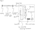
- a gas permeability was measured according to a method described in " Shoushitsu Mokei you Tokeizai no Hyoujun Shiken Houhou (standard test method for coating agent for lost pattern), Chapter 5: method for measuring a gas permeability", Japan Foundry Engineering Society, Kansai division, Mar., 1996 , based on JIS Z2601 (1993), "test method for molding sand", with an apparatus working by the same mechanism as of the apparatus for measuring a gas permeability (compressed air ventilating system) described in this publication (p. 24, Fig. 5-2).
- a thickness of a test piece was a wall thickness of a structure (I) or structure for casting (on which a surface layer was formed), or "(outer diameter - inner diameter)/2", and a cross-sectional area of a test piece was "inner diameter ⁇ pi ⁇ length”.
- the gas permeability measuring instrument was attached with a rubber tube and a connection tool (packing) in order to connect to a hollow part of a produced straight or elbow tube for the sprue runner (in FIG. 2 , shown as a sample to be measured) without leakage.
- the straight or elbow tube was, at one end of the hollow part, tightly fitted with the connection tool, and at the other end, closed with a packing to prevent air from leaking therefrom, and subjected to the measurement.
- the sprue runner composed of two straight tubes and two elbow tubes was used, and thus the gas permeability of a structure (I) or structure for casting meant an average gas permeability of these four elements individually measured.
- the thickness of a surface layer formed on the surface of a structure (I) was determined by measuring the difference in thickness between the structure for casting having the surface layer formed thereon and the structure (I) before the surface layer was formed.
- the thickness of the structure (I) before the surface layer was formed was determined by measuring at ten marked positions, which were arbitrarily selected, with a dial caliper gauge [Mitutoyo Corporation, code No. 209-611, reference number DCGO-50RL] and calculating an average thereof .
- the thickness of the structure for casting having the surface layer formed thereon was determined by measuring at corresponding ten positions to the marked positions on the structure (I) with a dial caliper gauge [Mitutoyo Corporation, order No.209-611, code number DCGO-50RL] and calculating an average thereof.
- Detachability of a surface layer formed on the surface of the structure (I) was determined by scratching the surface of the structure for casting having the surface layer with a plastic cutter to make 84 squares and counting the number of squares in which the surface layer was detached. Six structures were subjected to the measurement to calculate an average number of detached squares. In Table 1, the result is shown in the column of "the number of detached surface layers".
- a water-soluble phenol resin mold as shown in FIG. 1 was built, in which a casting runner 1 was constructed using the produced structures for casting and connected to a cavity part 2 producing a toroidal cast component, which had an outer diameter of 240 mm, an inner diameter of 140 mm, and a thickness of 30 mm, and had a flow off.
- the casting runner 1 included the straight tube 11 (diameter: 50 mm, length: 150 mm) buried in the upper part of the mold (in FIG. 1 , above the mold parting plane) and a composite member buried in the lower part of the mold (in FIG. 1 , below the mold parting plane).
- a new sand Kao-Quaker Co., Ltd., "Lunamos #60"
- 1.1 parts by mass of water-soluble phenol resin Kao-Quaker Co., Ltd., "Kao Step SL6000, relative to 100 parts by mass of the sand
- 20 parts by mass of curing agent Kao-Quaker Co., Ltd., "DH-15", relative to 100 parts by mass of the water-soluble phenol resin
- a casting mass was 20 kg, and a mold mass was100 kg.
- the cast steel was subjected to x-ray transmission imaging to measure an area of gas defects in the cast steel.
- An image analyzing software "Winroof" was used to calculate an area of gas defects in the cast steel.
- the smaller area of gas defects in a cast steel means the cast steel has the higher quality with the less gas defects .
- Table 1 The result is shown in Table 1.
- Structures for casting were produced and used to cast a molten metal in the same way as in Example 2, except that hollow ceramic particles [Taiheiyo Cement Corporation, product name: E-SPHERES SL125, average particle diameter: 80 ⁇ m, apparent specific gravity: 0.8, bulk specific gravity: 0.34] were used as inorganic particles (A) and each structure (I) had a composition as shown in Table 1. Evaluation results of the structures by the same methods as in Example 1 are shown in Table 1.
Landscapes
- Engineering & Computer Science (AREA)
- Mechanical Engineering (AREA)
- Chemical & Material Sciences (AREA)
- Materials Engineering (AREA)
- Mold Materials And Core Materials (AREA)
- Molds, Cores, And Manufacturing Methods Thereof (AREA)
Claims (15)
- Structure de coulée comprenant une fibre organique, une fibre inorganique, des particules inorganiques (A) ayant un diamètre particulaire moyen de 80 à 90 µm et un liant (a),
ayant une couche de surface comprenant des particules inorganiques réfractaires (B) ayant un diamètre particulaire moyen de 10 à 30 µm choisies dans le groupe constitué des oxydes de métaux et des silicates de métaux, d'un minéral argileux et d'un liant (b) sur la surface de la structure. - Structure de coulée selon la revendication 1, dans laquelle un rapport du diamètre particulaire moyen des particules inorganiques (A) aux particules inorganiques réfractaires (B) [diamètre particulaire moyen des particules inorganiques (A)]/[diamètre particulaire moyen des particules inorganiques réfractaires (B)] est de 1 à 35.
- Structure de coulée selon la revendication 1 ou 2, dans laquelle une proportion du minéral argileux est de 0,5 à 30 parties en masse par rapport à 100 parties en masse de particules inorganiques (B).
- Structure de coulée selon l'une quelconque des revendications 1 à 3, dans laquelle une proportion de la couche de surface est de 10 à 80 % en masse de la structure de coulée sur la base de la masse de la structure de coulée.
- Structure de coulée selon l'une quelconque des revendications 1 à 4, dans laquelle la particule inorganique (A) est au moins l'une choisie dans le groupe constitué du graphite, du mica, de la silice, de la céramique creuse et des cendres volantes.
- Structure de coulée selon l'une quelconque des revendications 1 à 5, dans laquelle les particules inorganiques réfractaires (B) sont au moins l'une choisie dans le groupe constitué de la mullite, du zircon, de l'oxyde de zirconium, de l'alumine, de l'olivine, des spinelles, de la magnésie et de la chromite.
- Structure de coulée selon l'une quelconque des revendications 1 à 6, dans laquelle le minéral argileux est au moins l'un choisi dans le groupe constitué de l'attapulgite, de la sépiolite, de la bentonite et de la smectite.
- Structure de coulée selon l'une quelconque des revendications 1 à 7, dans laquelle le liant (b) est un liant inorganique.
- Structure de coulée selon l'une quelconque des revendications 1 à 8, dans laquelle la couche de surface est présente sur le côté venant en contact avec un métal fondu.
- Structure de coulée selon l'une quelconque des revendications 1 à 9, dans laquelle la couche de surface comprend des particules de zircon comme particules inorganiques réfractaires (B), de l'attapulgite comme minéral argileux et de la silice colloïdale comme liant (b).
- Structure de coulée selon l'une quelconque des revendications 1 à 10, comprenant la fibre organique à raison de 3 à 25 % en masse, la fibre inorganique à raison de 3,5 à 20% en masse, les particules inorganiques (A) à raison de 1 à 70% en masse et le liant (a) à raison de 3 à 40 % en masse.
- Procédé de production d'une structure de coulée, comprenant les étapes consistant à :préparer une structure (I) à partir d'une suspension brute comprenant une fibre organique, une fibre inorganique, des particules inorganiques (A) ayant un diamètre particulaire moyen de 80 à 90 µm, un liant (a) et un milieu dispersant via un procédé de moulage comprenant une étape papetière ; etformer une couche de surface comprenant des particules inorganiques réfractaires (B) ayant un diamètre particulaire moyen de 10 à 30 µm choisies dans le groupe constitué des oxydes de métaux et des silicates de métaux, d'un minéral argileux et d'un liant (b) sur la surface de la structure (I).
- Procédé de production d'une structure de coulée selon la revendication 12, comprenant l'étape de préparation d'une structure (I) via un procédé de moulage comprenant une étape papetière, puis l'étape de formation de la couche de surface.
- Utilisation de la structure de coulée selon l'une quelconque des revendications 1 à 11 pour couler un article moulé.
- Procédé de coulée d'un article moulé avec la structure de coulée selon l'une quelconque des revendications 1 à 11.
Applications Claiming Priority (2)
| Application Number | Priority Date | Filing Date | Title |
|---|---|---|---|
| JP2010145199 | 2010-06-25 | ||
| PCT/JP2011/064496 WO2011162365A1 (fr) | 2010-06-25 | 2011-06-24 | Structure pour la production de matériau de coulée |
Publications (3)
| Publication Number | Publication Date |
|---|---|
| EP2586545A1 EP2586545A1 (fr) | 2013-05-01 |
| EP2586545A4 EP2586545A4 (fr) | 2017-09-06 |
| EP2586545B1 true EP2586545B1 (fr) | 2018-11-21 |
Family
ID=45371531
Family Applications (1)
| Application Number | Title | Priority Date | Filing Date |
|---|---|---|---|
| EP11798246.2A Active EP2586545B1 (fr) | 2010-06-25 | 2011-06-24 | Structure pour la production de matériau de coulée |
Country Status (7)
| Country | Link |
|---|---|
| US (1) | US8662146B2 (fr) |
| EP (1) | EP2586545B1 (fr) |
| JP (1) | JP5680490B2 (fr) |
| KR (1) | KR20130111229A (fr) |
| CN (1) | CN102933332B (fr) |
| ES (1) | ES2702101T3 (fr) |
| WO (1) | WO2011162365A1 (fr) |
Families Citing this family (23)
| Publication number | Priority date | Publication date | Assignee | Title |
|---|---|---|---|---|
| WO2014104045A1 (fr) * | 2012-12-28 | 2014-07-03 | 花王株式会社 | Procédé de production d'une structure de coulage et structure de type moule |
| US9073001B2 (en) * | 2013-02-14 | 2015-07-07 | The Boeing Company | Monolithic contactor and associated system and method for collecting carbon dioxide |
| JP6037977B2 (ja) * | 2013-08-26 | 2016-12-07 | 花王株式会社 | 消失模型用塗型剤組成物 |
| CN104117625A (zh) * | 2014-06-26 | 2014-10-29 | 芜湖市鸿坤汽车零部件有限公司 | 一种废保温砖醇基铸造涂料及其制作方法 |
| JP6235448B2 (ja) * | 2014-12-02 | 2017-11-22 | 花王株式会社 | 消失模型用塗型剤組成物 |
| CN106111883A (zh) * | 2016-08-18 | 2016-11-16 | 娄土岭 | 一种多功能铸造型砂及其制造方法 |
| CN106216608B (zh) * | 2016-09-30 | 2018-10-30 | 常州万兴纸塑有限公司 | 铸造用浇道管制备方法 |
| CN106734872A (zh) * | 2016-11-10 | 2017-05-31 | 安徽龙氏机械制造有限公司 | 一种粉煤灰铸铁涂料的制备方法 |
| CN107021763A (zh) * | 2016-12-30 | 2017-08-08 | 宁夏共享能源有限公司 | 用再生砂制备的铸件浇注系统构件及其制备方法 |
| CN107116182A (zh) * | 2016-12-30 | 2017-09-01 | 宁夏共享能源有限公司 | 铸造用浇注系统部件及其成型方法 |
| CN107096891A (zh) * | 2017-04-26 | 2017-08-29 | 常州万兴纸塑有限公司 | 高温纤维纸质浇口杯的制备方法 |
| TWI630041B (zh) * | 2017-05-09 | 2018-07-21 | 皇廣鑄造發展股份有限公司 | 鑄造用澆道保護管及其製造方法 |
| JP6509416B1 (ja) * | 2017-11-20 | 2019-05-08 | 花王株式会社 | 鋳物製造用構造体 |
| CN113043424B (zh) * | 2019-12-26 | 2023-01-31 | 济南圣泉集团股份有限公司 | 浇注系统的流道组件的制备方法及浇注系统的流道组件 |
| JP7356394B2 (ja) * | 2020-04-10 | 2023-10-04 | ユシロ化学工業株式会社 | ダイカスト用水性離型剤 |
| JP7078789B2 (ja) * | 2020-11-09 | 2022-05-31 | 花王株式会社 | 鋳物製造用構造体 |
| CN113510961A (zh) * | 2021-09-07 | 2021-10-19 | 广汉市福客科技有限公司 | 一种自发泡固体泡排球模具及其制备方法 |
| JP7249450B1 (ja) * | 2022-04-01 | 2023-03-30 | 花王株式会社 | 鋳物製造用構造体 |
| JP7295310B1 (ja) | 2022-05-23 | 2023-06-20 | 花王株式会社 | 鋳物製造用構造体、その製造方法、及びそれを用いた鋳物の製造方法 |
| CN117102435A (zh) * | 2022-05-23 | 2023-11-24 | 花王株式会社 | 铸件制造用结构体 |
| JP7441997B1 (ja) * | 2022-12-09 | 2024-03-01 | イビデン株式会社 | 無機繊維マットの製造方法、及び、無機繊維マット |
| GB2636919B (en) * | 2023-09-19 | 2026-01-14 | Kao Corp | Structure for producing casting |
| CN119407096B (zh) * | 2024-12-04 | 2025-06-17 | 中山大简科技有限公司 | 铝合金3d打印光敏树脂成模熔模铸造涂料及其制备方法 |
Family Cites Families (13)
| Publication number | Priority date | Publication date | Assignee | Title |
|---|---|---|---|---|
| JPH05138296A (ja) * | 1991-11-22 | 1993-06-01 | Toshiba Corp | 中空鋳物製造用鋳型 |
| JPH08257673A (ja) | 1995-03-23 | 1996-10-08 | Mitsubishi Heavy Ind Ltd | セラミック製鋳型 |
| JPH10142840A (ja) | 1996-11-15 | 1998-05-29 | Minolta Co Ltd | 静電潜像現像用トナー |
| JP4162065B2 (ja) * | 1998-10-13 | 2008-10-08 | 株式会社フジコー | 耐摩耗材の製造方法 |
| JP3995649B2 (ja) * | 2002-11-29 | 2007-10-24 | 花王株式会社 | 鋳物製造用の鋳型又は構造体 |
| EP1754554B1 (fr) * | 2004-06-10 | 2019-03-06 | Kao Corporation | Structure destinée à la production de pièces coulées |
| CN100551581C (zh) * | 2005-05-20 | 2009-10-21 | 花王株式会社 | 成形体及其制造方法 |
| JP4672522B2 (ja) * | 2005-06-16 | 2011-04-20 | 花王株式会社 | 鋳物製造用構造体 |
| WO2007063888A1 (fr) * | 2005-11-30 | 2007-06-07 | Kao Corporation | Composant pour la production de pièces coulées et son procédé de fabrication |
| JP4907326B2 (ja) * | 2006-12-12 | 2012-03-28 | 花王株式会社 | 鋳物製造用構造体及び鋳物の製造方法 |
| JP5441402B2 (ja) * | 2008-01-22 | 2014-03-12 | 花王株式会社 | 鋳物製造用構造体、鋳物製造用構造体用組成物、鋳物製造用構造体の製造方法、及び鋳物の製造方法 |
| DE102008025311A1 (de) * | 2008-05-27 | 2009-12-03 | Ashland-Südchemie-Kernfest GmbH | Geruchs- und schadstoffadsorbierende Beschichtungsmasse für den kastengebundenen Metallguss |
| JP5473312B2 (ja) | 2008-12-18 | 2014-04-16 | 花王株式会社 | 鋳物製造用構造体の製造方法 |
-
2011
- 2011-06-22 JP JP2011138172A patent/JP5680490B2/ja active Active
- 2011-06-24 CN CN201180028505.3A patent/CN102933332B/zh active Active
- 2011-06-24 KR KR1020127032900A patent/KR20130111229A/ko not_active Ceased
- 2011-06-24 WO PCT/JP2011/064496 patent/WO2011162365A1/fr not_active Ceased
- 2011-06-24 ES ES11798246T patent/ES2702101T3/es active Active
- 2011-06-24 EP EP11798246.2A patent/EP2586545B1/fr active Active
- 2011-06-24 US US13/701,130 patent/US8662146B2/en active Active
Non-Patent Citations (1)
| Title |
|---|
| None * |
Also Published As
| Publication number | Publication date |
|---|---|
| EP2586545A1 (fr) | 2013-05-01 |
| WO2011162365A1 (fr) | 2011-12-29 |
| JP5680490B2 (ja) | 2015-03-04 |
| US20130105103A1 (en) | 2013-05-02 |
| KR20130111229A (ko) | 2013-10-10 |
| JP2012024841A (ja) | 2012-02-09 |
| ES2702101T3 (es) | 2019-02-27 |
| CN102933332B (zh) | 2015-12-16 |
| US8662146B2 (en) | 2014-03-04 |
| CN102933332A (zh) | 2013-02-13 |
| EP2586545A4 (fr) | 2017-09-06 |
Similar Documents
| Publication | Publication Date | Title |
|---|---|---|
| EP2586545B1 (fr) | Structure pour la production de matériau de coulée | |
| EP1754554B1 (fr) | Structure destinée à la production de pièces coulées | |
| JP7217218B2 (ja) | 鋳物製造用構造体 | |
| JP2004195547A (ja) | 鋳物製造用抄造部品 | |
| EP2939759B1 (fr) | Procédé de production d'une structure de coulage et structure de type moule | |
| JP4675276B2 (ja) | 成形体 | |
| JP3995649B2 (ja) | 鋳物製造用の鋳型又は構造体 | |
| JP4672522B2 (ja) | 鋳物製造用構造体 | |
| JP4869786B2 (ja) | 鋳物製造用構造体 | |
| JP4672289B2 (ja) | 鋳物製造用構造体及びその製造方法、並びに鋳物 | |
| JP3241628U (ja) | 鋳物製造用構造体 | |
| JP2004181472A (ja) | 鋳物製造用の鋳型及び構造体 | |
| CN117102435A (zh) | 铸件制造用结构体 | |
| JP7295310B1 (ja) | 鋳物製造用構造体、その製造方法、及びそれを用いた鋳物の製造方法 | |
| JP4907326B2 (ja) | 鋳物製造用構造体及び鋳物の製造方法 | |
| US20250091119A1 (en) | Structure for producing casting | |
| JP7245369B1 (ja) | 鋳物製造用構造体 |
Legal Events
| Date | Code | Title | Description |
|---|---|---|---|
| PUAI | Public reference made under article 153(3) epc to a published international application that has entered the european phase |
Free format text: ORIGINAL CODE: 0009012 |
|
| 17P | Request for examination filed |
Effective date: 20121207 |
|
| AK | Designated contracting states |
Kind code of ref document: A1 Designated state(s): AL AT BE BG CH CY CZ DE DK EE ES FI FR GB GR HR HU IE IS IT LI LT LU LV MC MK MT NL NO PL PT RO RS SE SI SK SM TR |
|
| DAX | Request for extension of the european patent (deleted) | ||
| RA4 | Supplementary search report drawn up and despatched (corrected) |
Effective date: 20170808 |
|
| RIC1 | Information provided on ipc code assigned before grant |
Ipc: B22C 1/00 20060101AFI20170801BHEP Ipc: B22C 9/02 20060101ALI20170801BHEP Ipc: B22C 9/08 20060101ALI20170801BHEP |
|
| GRAP | Despatch of communication of intention to grant a patent |
Free format text: ORIGINAL CODE: EPIDOSNIGR1 |
|
| STAA | Information on the status of an ep patent application or granted ep patent |
Free format text: STATUS: GRANT OF PATENT IS INTENDED |
|
| INTG | Intention to grant announced |
Effective date: 20180604 |
|
| GRAS | Grant fee paid |
Free format text: ORIGINAL CODE: EPIDOSNIGR3 |
|
| GRAJ | Information related to disapproval of communication of intention to grant by the applicant or resumption of examination proceedings by the epo deleted |
Free format text: ORIGINAL CODE: EPIDOSDIGR1 |
|
| GRAL | Information related to payment of fee for publishing/printing deleted |
Free format text: ORIGINAL CODE: EPIDOSDIGR3 |
|
| STAA | Information on the status of an ep patent application or granted ep patent |
Free format text: STATUS: REQUEST FOR EXAMINATION WAS MADE |
|
| INTC | Intention to grant announced (deleted) | ||
| GRAR | Information related to intention to grant a patent recorded |
Free format text: ORIGINAL CODE: EPIDOSNIGR71 |
|
| STAA | Information on the status of an ep patent application or granted ep patent |
Free format text: STATUS: GRANT OF PATENT IS INTENDED |
|
| GRAA | (expected) grant |
Free format text: ORIGINAL CODE: 0009210 |
|
| STAA | Information on the status of an ep patent application or granted ep patent |
Free format text: STATUS: THE PATENT HAS BEEN GRANTED |
|
| INTG | Intention to grant announced |
Effective date: 20181011 |
|
| AK | Designated contracting states |
Kind code of ref document: B1 Designated state(s): AL AT BE BG CH CY CZ DE DK EE ES FI FR GB GR HR HU IE IS IT LI LT LU LV MC MK MT NL NO PL PT RO RS SE SI SK SM TR |
|
| REG | Reference to a national code |
Ref country code: CH Ref legal event code: EP |
|
| REG | Reference to a national code |
Ref country code: IE Ref legal event code: FG4D |
|
| REG | Reference to a national code |
Ref country code: DE Ref legal event code: R096 Ref document number: 602011054126 Country of ref document: DE |
|
| REG | Reference to a national code |
Ref country code: AT Ref legal event code: REF Ref document number: 1066969 Country of ref document: AT Kind code of ref document: T Effective date: 20181215 |
|
| REG | Reference to a national code |
Ref country code: ES Ref legal event code: FG2A Ref document number: 2702101 Country of ref document: ES Kind code of ref document: T3 Effective date: 20190227 |
|
| REG | Reference to a national code |
Ref country code: NL Ref legal event code: MP Effective date: 20181121 |
|
| REG | Reference to a national code |
Ref country code: AT Ref legal event code: MK05 Ref document number: 1066969 Country of ref document: AT Kind code of ref document: T Effective date: 20181121 |
|
| PG25 | Lapsed in a contracting state [announced via postgrant information from national office to epo] |
Ref country code: BG Free format text: LAPSE BECAUSE OF FAILURE TO SUBMIT A TRANSLATION OF THE DESCRIPTION OR TO PAY THE FEE WITHIN THE PRESCRIBED TIME-LIMIT Effective date: 20190221 Ref country code: NO Free format text: LAPSE BECAUSE OF FAILURE TO SUBMIT A TRANSLATION OF THE DESCRIPTION OR TO PAY THE FEE WITHIN THE PRESCRIBED TIME-LIMIT Effective date: 20190221 Ref country code: IS Free format text: LAPSE BECAUSE OF FAILURE TO SUBMIT A TRANSLATION OF THE DESCRIPTION OR TO PAY THE FEE WITHIN THE PRESCRIBED TIME-LIMIT Effective date: 20190321 Ref country code: LT Free format text: LAPSE BECAUSE OF FAILURE TO SUBMIT A TRANSLATION OF THE DESCRIPTION OR TO PAY THE FEE WITHIN THE PRESCRIBED TIME-LIMIT Effective date: 20181121 Ref country code: LV Free format text: LAPSE BECAUSE OF FAILURE TO SUBMIT A TRANSLATION OF THE DESCRIPTION OR TO PAY THE FEE WITHIN THE PRESCRIBED TIME-LIMIT Effective date: 20181121 Ref country code: HR Free format text: LAPSE BECAUSE OF FAILURE TO SUBMIT A TRANSLATION OF THE DESCRIPTION OR TO PAY THE FEE WITHIN THE PRESCRIBED TIME-LIMIT Effective date: 20181121 Ref country code: AT Free format text: LAPSE BECAUSE OF FAILURE TO SUBMIT A TRANSLATION OF THE DESCRIPTION OR TO PAY THE FEE WITHIN THE PRESCRIBED TIME-LIMIT Effective date: 20181121 Ref country code: FI Free format text: LAPSE BECAUSE OF FAILURE TO SUBMIT A TRANSLATION OF THE DESCRIPTION OR TO PAY THE FEE WITHIN THE PRESCRIBED TIME-LIMIT Effective date: 20181121 |
|
| PG25 | Lapsed in a contracting state [announced via postgrant information from national office to epo] |
Ref country code: PT Free format text: LAPSE BECAUSE OF FAILURE TO SUBMIT A TRANSLATION OF THE DESCRIPTION OR TO PAY THE FEE WITHIN THE PRESCRIBED TIME-LIMIT Effective date: 20190321 Ref country code: SE Free format text: LAPSE BECAUSE OF FAILURE TO SUBMIT A TRANSLATION OF THE DESCRIPTION OR TO PAY THE FEE WITHIN THE PRESCRIBED TIME-LIMIT Effective date: 20181121 Ref country code: AL Free format text: LAPSE BECAUSE OF FAILURE TO SUBMIT A TRANSLATION OF THE DESCRIPTION OR TO PAY THE FEE WITHIN THE PRESCRIBED TIME-LIMIT Effective date: 20181121 Ref country code: GR Free format text: LAPSE BECAUSE OF FAILURE TO SUBMIT A TRANSLATION OF THE DESCRIPTION OR TO PAY THE FEE WITHIN THE PRESCRIBED TIME-LIMIT Effective date: 20190222 Ref country code: RS Free format text: LAPSE BECAUSE OF FAILURE TO SUBMIT A TRANSLATION OF THE DESCRIPTION OR TO PAY THE FEE WITHIN THE PRESCRIBED TIME-LIMIT Effective date: 20181121 Ref country code: NL Free format text: LAPSE BECAUSE OF FAILURE TO SUBMIT A TRANSLATION OF THE DESCRIPTION OR TO PAY THE FEE WITHIN THE PRESCRIBED TIME-LIMIT Effective date: 20181121 |
|
| PG25 | Lapsed in a contracting state [announced via postgrant information from national office to epo] |
Ref country code: DK Free format text: LAPSE BECAUSE OF FAILURE TO SUBMIT A TRANSLATION OF THE DESCRIPTION OR TO PAY THE FEE WITHIN THE PRESCRIBED TIME-LIMIT Effective date: 20181121 Ref country code: PL Free format text: LAPSE BECAUSE OF FAILURE TO SUBMIT A TRANSLATION OF THE DESCRIPTION OR TO PAY THE FEE WITHIN THE PRESCRIBED TIME-LIMIT Effective date: 20181121 Ref country code: CZ Free format text: LAPSE BECAUSE OF FAILURE TO SUBMIT A TRANSLATION OF THE DESCRIPTION OR TO PAY THE FEE WITHIN THE PRESCRIBED TIME-LIMIT Effective date: 20181121 |
|
| REG | Reference to a national code |
Ref country code: DE Ref legal event code: R097 Ref document number: 602011054126 Country of ref document: DE |
|
| PG25 | Lapsed in a contracting state [announced via postgrant information from national office to epo] |
Ref country code: SM Free format text: LAPSE BECAUSE OF FAILURE TO SUBMIT A TRANSLATION OF THE DESCRIPTION OR TO PAY THE FEE WITHIN THE PRESCRIBED TIME-LIMIT Effective date: 20181121 Ref country code: EE Free format text: LAPSE BECAUSE OF FAILURE TO SUBMIT A TRANSLATION OF THE DESCRIPTION OR TO PAY THE FEE WITHIN THE PRESCRIBED TIME-LIMIT Effective date: 20181121 Ref country code: RO Free format text: LAPSE BECAUSE OF FAILURE TO SUBMIT A TRANSLATION OF THE DESCRIPTION OR TO PAY THE FEE WITHIN THE PRESCRIBED TIME-LIMIT Effective date: 20181121 Ref country code: SK Free format text: LAPSE BECAUSE OF FAILURE TO SUBMIT A TRANSLATION OF THE DESCRIPTION OR TO PAY THE FEE WITHIN THE PRESCRIBED TIME-LIMIT Effective date: 20181121 |
|
| PLBE | No opposition filed within time limit |
Free format text: ORIGINAL CODE: 0009261 |
|
| STAA | Information on the status of an ep patent application or granted ep patent |
Free format text: STATUS: NO OPPOSITION FILED WITHIN TIME LIMIT |
|
| 26N | No opposition filed |
Effective date: 20190822 |
|
| PG25 | Lapsed in a contracting state [announced via postgrant information from national office to epo] |
Ref country code: SI Free format text: LAPSE BECAUSE OF FAILURE TO SUBMIT A TRANSLATION OF THE DESCRIPTION OR TO PAY THE FEE WITHIN THE PRESCRIBED TIME-LIMIT Effective date: 20181121 |
|
| PG25 | Lapsed in a contracting state [announced via postgrant information from national office to epo] |
Ref country code: MC Free format text: LAPSE BECAUSE OF FAILURE TO SUBMIT A TRANSLATION OF THE DESCRIPTION OR TO PAY THE FEE WITHIN THE PRESCRIBED TIME-LIMIT Effective date: 20181121 |
|
| REG | Reference to a national code |
Ref country code: CH Ref legal event code: PL |
|
| GBPC | Gb: european patent ceased through non-payment of renewal fee |
Effective date: 20190624 |
|
| REG | Reference to a national code |
Ref country code: BE Ref legal event code: MM Effective date: 20190630 |
|
| PG25 | Lapsed in a contracting state [announced via postgrant information from national office to epo] |
Ref country code: TR Free format text: LAPSE BECAUSE OF FAILURE TO SUBMIT A TRANSLATION OF THE DESCRIPTION OR TO PAY THE FEE WITHIN THE PRESCRIBED TIME-LIMIT Effective date: 20181121 |
|
| PG25 | Lapsed in a contracting state [announced via postgrant information from national office to epo] |
Ref country code: GB Free format text: LAPSE BECAUSE OF NON-PAYMENT OF DUE FEES Effective date: 20190624 Ref country code: IE Free format text: LAPSE BECAUSE OF NON-PAYMENT OF DUE FEES Effective date: 20190624 |
|
| PG25 | Lapsed in a contracting state [announced via postgrant information from national office to epo] |
Ref country code: BE Free format text: LAPSE BECAUSE OF NON-PAYMENT OF DUE FEES Effective date: 20190630 Ref country code: CH Free format text: LAPSE BECAUSE OF NON-PAYMENT OF DUE FEES Effective date: 20190630 Ref country code: LI Free format text: LAPSE BECAUSE OF NON-PAYMENT OF DUE FEES Effective date: 20190630 Ref country code: LU Free format text: LAPSE BECAUSE OF NON-PAYMENT OF DUE FEES Effective date: 20190624 |
|
| PG25 | Lapsed in a contracting state [announced via postgrant information from national office to epo] |
Ref country code: CY Free format text: LAPSE BECAUSE OF FAILURE TO SUBMIT A TRANSLATION OF THE DESCRIPTION OR TO PAY THE FEE WITHIN THE PRESCRIBED TIME-LIMIT Effective date: 20181121 |
|
| PG25 | Lapsed in a contracting state [announced via postgrant information from national office to epo] |
Ref country code: MT Free format text: LAPSE BECAUSE OF FAILURE TO SUBMIT A TRANSLATION OF THE DESCRIPTION OR TO PAY THE FEE WITHIN THE PRESCRIBED TIME-LIMIT Effective date: 20181121 Ref country code: HU Free format text: LAPSE BECAUSE OF FAILURE TO SUBMIT A TRANSLATION OF THE DESCRIPTION OR TO PAY THE FEE WITHIN THE PRESCRIBED TIME-LIMIT; INVALID AB INITIO Effective date: 20110624 |
|
| PG25 | Lapsed in a contracting state [announced via postgrant information from national office to epo] |
Ref country code: MK Free format text: LAPSE BECAUSE OF FAILURE TO SUBMIT A TRANSLATION OF THE DESCRIPTION OR TO PAY THE FEE WITHIN THE PRESCRIBED TIME-LIMIT Effective date: 20181121 |
|
| P01 | Opt-out of the competence of the unified patent court (upc) registered |
Effective date: 20230522 |
|
| PGFP | Annual fee paid to national office [announced via postgrant information from national office to epo] |
Ref country code: DE Payment date: 20250429 Year of fee payment: 15 |
|
| PGFP | Annual fee paid to national office [announced via postgrant information from national office to epo] |
Ref country code: IT Payment date: 20250522 Year of fee payment: 15 |
|
| PGFP | Annual fee paid to national office [announced via postgrant information from national office to epo] |
Ref country code: FR Payment date: 20250508 Year of fee payment: 15 |
|
| PGFP | Annual fee paid to national office [announced via postgrant information from national office to epo] |
Ref country code: ES Payment date: 20250701 Year of fee payment: 15 |