EP2586587B1 - Vorrichtung und Verfahren zur Herstellung eines Gegenstands mittels Spritzgießwerkzeug - Google Patents
Vorrichtung und Verfahren zur Herstellung eines Gegenstands mittels Spritzgießwerkzeug Download PDFInfo
- Publication number
- EP2586587B1 EP2586587B1 EP12184462.5A EP12184462A EP2586587B1 EP 2586587 B1 EP2586587 B1 EP 2586587B1 EP 12184462 A EP12184462 A EP 12184462A EP 2586587 B1 EP2586587 B1 EP 2586587B1
- Authority
- EP
- European Patent Office
- Prior art keywords
- component
- detecting
- detection device
- accommodating
- needle
- Prior art date
- Legal status (The legal status is an assumption and is not a legal conclusion. Google has not performed a legal analysis and makes no representation as to the accuracy of the status listed.)
- Active
Links
Images



Classifications
-
- B—PERFORMING OPERATIONS; TRANSPORTING
- B29—WORKING OF PLASTICS; WORKING OF SUBSTANCES IN A PLASTIC STATE IN GENERAL
- B29C—SHAPING OR JOINING OF PLASTICS; SHAPING OF MATERIAL IN A PLASTIC STATE, NOT OTHERWISE PROVIDED FOR; AFTER-TREATMENT OF THE SHAPED PRODUCTS, e.g. REPAIRING
- B29C45/00—Injection moulding, i.e. forcing the required volume of moulding material through a nozzle into a closed mould; Apparatus therefor
- B29C45/14—Injection moulding, i.e. forcing the required volume of moulding material through a nozzle into a closed mould; Apparatus therefor incorporating preformed parts or layers, e.g. injection moulding around inserts or for coating articles
- B29C45/14065—Positioning or centering articles in the mould
-
- B—PERFORMING OPERATIONS; TRANSPORTING
- B29—WORKING OF PLASTICS; WORKING OF SUBSTANCES IN A PLASTIC STATE IN GENERAL
- B29C—SHAPING OR JOINING OF PLASTICS; SHAPING OF MATERIAL IN A PLASTIC STATE, NOT OTHERWISE PROVIDED FOR; AFTER-TREATMENT OF THE SHAPED PRODUCTS, e.g. REPAIRING
- B29C45/00—Injection moulding, i.e. forcing the required volume of moulding material through a nozzle into a closed mould; Apparatus therefor
- B29C45/17—Component parts, details or accessories; Auxiliary operations
- B29C45/76—Measuring, controlling or regulating
- B29C45/768—Detecting defective moulding conditions
-
- B—PERFORMING OPERATIONS; TRANSPORTING
- B29—WORKING OF PLASTICS; WORKING OF SUBSTANCES IN A PLASTIC STATE IN GENERAL
- B29C—SHAPING OR JOINING OF PLASTICS; SHAPING OF MATERIAL IN A PLASTIC STATE, NOT OTHERWISE PROVIDED FOR; AFTER-TREATMENT OF THE SHAPED PRODUCTS, e.g. REPAIRING
- B29C2945/00—Indexing scheme relating to injection moulding, i.e. forcing the required volume of moulding material through a nozzle into a closed mould
- B29C2945/76—Measuring, controlling or regulating
- B29C2945/76003—Measured parameter
- B29C2945/76083—Position
-
- B—PERFORMING OPERATIONS; TRANSPORTING
- B29—WORKING OF PLASTICS; WORKING OF SUBSTANCES IN A PLASTIC STATE IN GENERAL
- B29C—SHAPING OR JOINING OF PLASTICS; SHAPING OF MATERIAL IN A PLASTIC STATE, NOT OTHERWISE PROVIDED FOR; AFTER-TREATMENT OF THE SHAPED PRODUCTS, e.g. REPAIRING
- B29C2945/00—Indexing scheme relating to injection moulding, i.e. forcing the required volume of moulding material through a nozzle into a closed mould
- B29C2945/76—Measuring, controlling or regulating
- B29C2945/76177—Location of measurement
- B29C2945/76254—Mould
- B29C2945/76257—Mould cavity
-
- B—PERFORMING OPERATIONS; TRANSPORTING
- B29—WORKING OF PLASTICS; WORKING OF SUBSTANCES IN A PLASTIC STATE IN GENERAL
- B29C—SHAPING OR JOINING OF PLASTICS; SHAPING OF MATERIAL IN A PLASTIC STATE, NOT OTHERWISE PROVIDED FOR; AFTER-TREATMENT OF THE SHAPED PRODUCTS, e.g. REPAIRING
- B29C2945/00—Indexing scheme relating to injection moulding, i.e. forcing the required volume of moulding material through a nozzle into a closed mould
- B29C2945/76—Measuring, controlling or regulating
- B29C2945/76177—Location of measurement
- B29C2945/76294—Inserts
-
- B—PERFORMING OPERATIONS; TRANSPORTING
- B29—WORKING OF PLASTICS; WORKING OF SUBSTANCES IN A PLASTIC STATE IN GENERAL
- B29K—INDEXING SCHEME ASSOCIATED WITH SUBCLASSES B29B, B29C OR B29D, RELATING TO MOULDING MATERIALS OR TO MATERIALS FOR MOULDS, REINFORCEMENTS, FILLERS OR PREFORMED PARTS, e.g. INSERTS
- B29K2705/00—Use of metals, their alloys or their compounds, for preformed parts, e.g. for inserts
-
- B—PERFORMING OPERATIONS; TRANSPORTING
- B29—WORKING OF PLASTICS; WORKING OF SUBSTANCES IN A PLASTIC STATE IN GENERAL
- B29L—INDEXING SCHEME ASSOCIATED WITH SUBCLASS B29C, RELATING TO PARTICULAR ARTICLES
- B29L2031/00—Other particular articles
- B29L2031/753—Medical equipment; Accessories therefor
- B29L2031/7544—Injection needles, syringes
Definitions
- the invention relates to an apparatus and a method for producing an article by means of injection molding. More particularly, the invention relates to an apparatus and method for making a lancet that can be used, for example, by a patient as a blood sampling lancing device for determining its blood glucose level.
- a device for producing a lancet In this device, a needle is inserted into a receiving device in a first part of the system. In a second part of the plant, the needle is injection-molded with a plastic. In a third part of the plant, the lancet produced in the second part of the plant is removed from the receiving device. In a fourth part of the plant, faulty lancets are sorted out and the defect-free lancets are transferred to a magazine.
- the correct function of the device is detected at least in the first and third parts of the installation by means of an optical detection device, for example a camera or a light barrier. The optical detection device checks, for example, by evaluating an image, whether the needles in the system part 1 are correct, so that they can be properly encapsulated in the system part 2.
- a needle usually has a very small diameter of less than 1 mm.
- the tip of the needle has an even smaller diameter.
- US 2004/0115294 A1 shows a machine with sensors for controlling a molding operation.
- a mold and a molding machine are indicated, which may be a blow molding machine used for a molding process with a preformed insert positioned in the mold.
- the sensor is used to detect a condition in the shape such as the position of the insert.
- the sensor may be a microswitch, a proximity sensor or an ultrasonic sensor.
- it does not disclose a populating device and an indication relating to an arrangement of a sensor surface.
- EP 1 057 586 A2 describes a tool for the forming, stamping or injection molding technique, which is provided with a functional surface.
- the tool includes a module, wherein in the plane of the surface of the module, a planar arrangement of a plurality of thin-film sensors is arranged.
- the device described above is very simple and can ensure trouble-free that the component is held on the receiving device only at the predetermined position. For example, as soon as a component touches the detection device, this is detected and the manufacturing process of the device can be stopped. In particular, it can be ensured that the placement device correctly equips the receiving device with the component.
- the detection device By carrying out the detection device with a sensor surface attached to the receiving device, the problems of optical sensors, such as reflections, reflections, etc., can be avoided.
- the device is due to the detection device significantly cheaper and less maintenance-prone than a device with a camera as a detection device, which includes protection devices and extensive software packages for capture and evaluation.
- the detection device is additionally arranged at least partially within the recess.
- the detection device is designed to detect whether a component is not held at the predetermined position on the receiving device.
- the detection device is designed to detect whether the placement device correctly equips the receiving device with the component, detects the area inside and / or outside the recess. In this way, virtually all types of misplaced components can be detected.
- the receiving device may have two contact surfaces for applying the component to the receiving device, wherein the detection device is configured to detect whether the component bears against the two contact surfaces.
- the detection device is a capacitive or inductive detection device or a piezo or pressure sensor or an ultrasonic sensor.
- the detection device is a thin-film sensor.
- the device may also be a control device for controlling the device on the basis of a detection result of the detection device.
- the device may comprise a plurality of receiving devices, which are equipped by the loading device in a predetermined time.
- the object is also achieved by a method for producing an article by means of injection molding tool according to claim 10.
- the invention is described below with reference to a device for producing a lancet. However, it is to be understood that the invention includes other devices for making another article, that is, not a lancet.
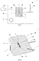
- Fig. 1 shows a device 1 for producing an article 5, in this case a lancet, according to a first embodiment.
- the device 1 has a first plant part 10, a second plant part 20, a third plant part 30 and a fourth plant part 40.
- the device 1 is described in more detail below.
- a lancet 5 produced by the device 1 is shown with a main body 6 and a needle 7.
- the needle 7 is fixed to the base body 6.
- the needle 7 is preferably made of stainless steel and has a diameter of less than 1 mm, for example 0.3 - 0.4 mm or even smaller.
- the tip of the needle 7 has an even smaller diameter.
- the lancet 5 can be used, for example, by a patient as a lancing device for blood sampling for the determination of its blood glucose value.
- the first part of the plant 10 serves Fig. 1 for positioning needles 7 at a predetermined position in which the needles 7 are to be held in the further production of the lancet 5.
- the second part of the plant 20 is used for injection molding.
- a plastic granules is melted and injected into a cavity, which is also called mold cavity or cavity and in which a needle 7 is located.
- the molded part of the mold can be removed.
- the plastic may in particular be PP, ABS, etc.
- the third piece of equipment 30 is used to remove the finished lancet 5 and possibly existing sprue.
- the fourth part of the plant 40 is used for bad part removal, ie for the rejection of defective lancets 5, and for the transfer of the finished lancets 5 to a magazine for storage or delivery of the lancet. 5
- Fig. 3 shows the device 1 at the first part of the plant 10 in more detail.
- the device 1 thus also comprises an upper tool part 50, a lower tool part 60 and a loading device 70.
- the loading device 70 is in Fig. 3 shown only very schematically and is used to load the lower tool part 60 with a component 7 of the article 5, in this case needles 7.
- the upper tool 50 has a plurality of centering holes 51, in each of which a centering pin 61 of the lower tool part 60 can be inserted.
- the upper tool part 50 and the lower tool part 60 can be arranged in a fixed predetermined position to each other.
- a spray nozzle 80 for spraying plastic in receiving devices 90 is provided on the upper tool 50.
- In the tool lower part 60 are in Fig. 3 a plurality of receiving devices 90 are arranged.
- the receiving devices 90 are connected to a flow channel 100, in which liquid plastic can flow between the receiving devices 90 in the second system part 20.
- On one of the receiving devices 90 two mispositioned needles 7
- Fig. 4 and Fig. 5 show the tool lower part 60 in more detail.
- a detection device 110 is mounted at each of the receptacles 90.
- the detection device 110 is a thin-film sensor or thin-film sensor which operates capacitively or inductively or may be a piezo or pressure sensor or an ultrasonic sensor.
- Each detector 110 is in Fig. 4 and Fig. 5 marked with diamonds.
- Each detection device 110 is arranged on a receiving device 90 in such a way that a needle 7, which is not correctly arranged in the receiving device 90 at the predetermined position provided for it, that is in the wrong position, is detected.
- Each detection device 110 has at least one sensor surface, which is attached to the receiving device 90. In the figures, the detection device 110 is each shown with only one sensor surface, so that the sensor surface is also designated by the reference numeral 110.
- the detection devices 110 are each connected to a signal cable 120 with a control device 130. For the sake of clarity, is in Fig. 4 only one of the detection devices 110, a signal cable 120 is shown.
- the detection device 110 Detects one of the detection devices 110 that a needle 7 is not at the intended, so they are correct, position, as in the receiving device 90 in the lower left quarter of the lower tool part 60 in Fig. 4 , and even better in Fig. 5 1, the detection device 110 outputs a signal to the control device 130 via the signal cable 120. It is signaled that a component 7, that is a needle 7, is not held at the predetermined position on the receiving device. If no wrong or mispositioned needle 7 is detected, the detection device 110 outputs no signal to the control device 190. When the controller 130 receives a signal from the detector 110, it stops the device 1 to allow the misplaced needle 7 to be removed.
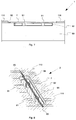
- Fig. 6 the arrangement of the detection device 110 is shown better on the receiving device 90.
- a needle 7 is correctly received in the receiving device 90 and thus correctly positioned.
- the correctly positioned needle 7 rests on two support members 91 which support the needle 7 at the correct, more precisely predetermined position.
- the support members 91 are designed as pins or bolts, which are spaced from each other in a recess 92 of the receiving device 90 are arranged.
- the needle 7 also abuts contact surfaces 93, which adjoin the depression 92.
- a correctly positioned needle 7 protrudes slightly beyond the recess 92 both at its tip and at its end and into the contact surfaces 93 arranged there.
- the contact surfaces 93 are thus arranged on the narrow sides of the rectangular recess 92. In this case, preferably all functions of the device 1 are stopped.
- Fig. 7 shows the arrangement of the detection device 110 in the region of the recess 92 and the contact surface or recesses 93 in a sectional view even better.
- the contact surfaces 93 are designed as recesses in the receiving device 90.
- the recess of the contact surface 93 has a smaller depth than the depth of the recess 92.
- the bolts 91 each have a notch 94, in which the needle 7 is inserted.
- the needle 7 is therefore at two points, namely the bolt 91 and more particularly their notches 94.
- the needle 7 is pressed lightly against a stop in the contact surfaces 93.
- the needle 7 abuts against the abutment surfaces 93, which may also be referred to as two points on which the needle 7 abuts.
- the detection device 110 extends to the edge of the contact surfaces or recesses 93 and to the edge of the recess 92 zoom. The latter is better in Fig. 6 shown.
- the detection device 110 is arranged outside the recess 92, in other words arranged around the recess 92.
- the detection device 110 is also arranged outside the contact surfaces 93, in other words arranged around the contact surfaces 93 around. There is no detection device 110 in the recess 92 and on the contact surfaces 93 or their recess in the receiving device 90.
- the mispositioned needles 7 may be detected by the detector 110 as previously described.
- the detection device 110 thus detects whether a component 7, ie a needle 7, is not held at the predetermined position on the receiving device 90. It can also be detected on the entire lower tool part 50, whether a component 7, that is, a needle 7, is not held at the predetermined position. Here it is checked in particular whether the loading device 70, the receiving device 90 properly equipped.
- Fig. 8 shows an enlarged partial view of a device 2 according to a second embodiment.
- the device 2 is largely constructed in the same way as the device 1 of the first embodiment. Therefore, the differences between the first and second embodiments will be described below mainly.
- Fig. 8 is a needle 7 correctly positioned in the receiving device 90.
- the detection device 110 is disposed outside the recess 92, in other words around the recess 92.
- the detection device 110 is also arranged outside the contact surfaces 93, in other words arranged around the contact surfaces 93 around.
- a detection device 111 is disposed within the recess 92. The detection device 111 is connected to the detection device 110, even if this is in Fig. 8 not shown.
- needle 7 can be detected, which are positioned incorrectly in the recess 92.
- the controller 130 when receiving a signal from the detector 110, may stop the device 2 to allow the misplaced needle 7 to be removed.
- the detection device 110 thus detects whether a component 7, ie a needle 7, is not held at the predetermined position on the receiving device.
- it is checked whether the loading device 70, the receiving device 90 correctly equipped.
- the detection device 111 may also check before insertion of the receiving devices 90 with needles 7, if all receiving devices 90 are free. That is, whether in a previous production of articles 5 at the plant part 3, all finished objects 5 were removed from the receiving devices 90.
- the control device 130 receives a signal from the detection device 111 that not all the receptacles 90 are free, it stops the device 2 so that the receptacle (s) 90 can be emptied.
- the detection device 110 can additionally be used to detect whether manufacturing residues project beyond the recess 92.
- the detection device 111 can detect whether a component 7, that is, a needle 7, is not held at the predetermined position on the receiving device.
- it is checked with the detection device 111 on the one hand, whether the loading device 70, the receiving device 90 properly equipped.
- Fig. 9 shows an enlarged partial sectional view of a device 3 according to a third embodiment.
- the device 3 is largely constructed in the same way as the device 1 of the first embodiment. Therefore, the differences between the first embodiment and the present embodiment will be described below mainly.
- a detection device 112 is also attached to the contact surfaces 93.
- the detection device 112 extends in the area of the contact surfaces 93 to the edge of Well 92 approach.
- no detection device is arranged in the depression 92.
- the detector 112 is therefore not present at the two points where the needle 7 rests, namely the notches 94 of the bolts 91. In addition, no detection device is present in the recess 92.
- the detection device 112 can also be used to reliably detect whether the needle 7 is correctly positioned on the receiving device 90. If the needle 7 is arranged in the predetermined position, the needle 7 is detected on both contact surfaces 93.
- the detection device 11 also detect mispositioned needles 7 on the receiving device 90.
- the detecting device 112 of this embodiment can also detect whether a component 7, that is, a needle 7, is not held at the predetermined position on the receiving device. Here, it is checked with the detection device 110 on the one hand, whether the loading device 70, the receiving device 90 properly equipped. On the other hand, the detection device 112 can check whether all receiving device (s) 90 are emptied before being equipped with the loading device 70.
- Such an embodiment represents a still further improvement in the detection of mispositioned needles and parts in the device 3 over the devices 1, 2 of the preceding embodiments. There are also the aforementioned advantages.
- the devices 1, 2, 3 of the described embodiments may also comprise fewer or more than four plant parts 10, 20, 30, 40.
- the devices 1, 2, 3 of the described embodiments can also produce more or fewer than four objects at a time.
- the receiving devices 90 are to be designed for receiving a corresponding number of components.
- only a receiving device 90 for receiving an object is conceivable.
- a device for producing lancets for example, 64 lancets can be manufactured simultaneously.
- Such a device may, for example, operate in a cycle in which the loading device 70 equips the receiving devices 90 with a plurality of needles in less than 10 seconds.
- the devices 1, 2, 3 of the embodiments are applicable to all devices in which components are received by a receiving device, in particular inserted into this.
- the devices 1, 2, 3 of the embodiments may, in place of an injection molding apparatus in particular also a punching, foaming, forming assembly device, etc. be.
- the respective detection device 110, 111, 112 instead of a connection of the detection devices 110, 111, 112 via a signal cable 120 to the control device 130, the respective detection device 110, 111, 112 also communicate wirelessly, ie wirelessly, with the control device 130.
- Detector 110 may not only be present on receptacle (s) 90. That is, the detection device 110 may be disposed on the entire surface of the tool lower part 60, which is associated with the tool top 50 and / or the mounting device 70.
- the detection device 111 may also be present on the two support elements 91 and detect whether the component 7 or the needle 7 is inserted into the indentations of the support elements 91.
- the detection device 111 may be present in particular in the notches 94 of the bolts 91.
- the detection device 110 can also be designed in such a way that the detection device 110 always outputs a signal to the control device 130 when the device is operated via the signal cable 120 when the function is correct.
- the signal of the detection means 110 is interrupted when a needle 7 is not in the predetermined position intended for them, such as in the receiving device 90 in the lower left quarter of the tool lower part 60 in Fig. 4 shown.
- the detection device 111 in the recess 92 and / or the detection device 112 can / can be carried out in the same way.
- the detection device 110 is preferably a three-layer thin-film sensor which has two layers each having a thickness of, for example, about 3 to 4 ⁇ m and preferably a chromium electrode which is arranged between the two sensor layers and has a thickness of, for example, about 200 nm.
- the chromium electrode may be sputtered onto one of the two layers.
- the chromium electrode can also be structured with a laser.
- One of the two layers may be a sensor layer, whereas the other layer may be an insulation and wear protection layer.
- the insulation and wear protection layer is preferably arranged as the uppermost layer on the receiving device 90.
- the detection device 111 and / or the detection device 112 are / is preferably carried out in the same way.
- two insulation and / or wear protection layers having a thickness of, for example, about 3 to 4 ⁇ m can be present in the detection device 110, between which a sensor layer having a thickness of, for example, about 200 nm is arranged.
- the detection device 111 and / or the detection device 112 are / is preferably carried out in the same way.
- the sensor layer is the sensor surface 110, which is attached to the receiving device 90 via the one of the two insulation and / or wear protection layers.
- the detection device 110 can be designed as a foil.
- the detection device 111 and / or the detection device 112 can / can be designed in the same way
- the detection device 110, or only one of its sensor surfaces, can be vapor-deposited on the receiving device 90.
- a PVD method Physical Vapor Deposition
- the detection device 111 and / or the detection device 112 can / can be designed in the same way.
- the detection device 110 or only one of its sensor surfaces, also be glued to the receiving device 90.
- the detection device 110, or only one of its sensor surfaces also be welded to the receiving device 90.
- the detection device 110, or only one of its sensor surfaces may also be laminated to the receiving device 90.
Landscapes
- Engineering & Computer Science (AREA)
- Manufacturing & Machinery (AREA)
- Mechanical Engineering (AREA)
- Moulds For Moulding Plastics Or The Like (AREA)
- Measurement Of The Respiration, Hearing Ability, Form, And Blood Characteristics Of Living Organisms (AREA)
Description
- Die Erfindung bezieht sich auf eine Vorrichtung und ein Verfahren zur Herstellung eines Gegenstands mittels Spritzgießwerkzeug. Insbesondere bezieht sich die Erfindung auf eine Vorrichtung und ein Verfahren zur Herstellung einer Lanzette, die beispielsweise von einem Patienten als Stechmittel zur Blutprobenentnahme für die Bestimmung seines Blutzuckerwerts verwendet werden kann.
- Firmenintern ist der Anmelderin eine Vorrichtung zur Herstellung einer Lanzette bekannt. Bei dieser Vorrichtung wird bei einem ersten Anlagenteil eine Nadel in eine Aufnahmeeinrichtung eingelegt. Bei einem zweiten Anlagenteil wird die Nadel durch Spritzgießen mit einem Kunststoff umgossen. Bei einem dritten Anlagenteil wird die im zweiten Anlagenteil hergestellte Lanzette von der Aufnahmeeinrichtung entnommen. Bei einem vierten Anlagenteil werden fehlerhafte Lanzetten aussortiert und die fehlerfreien Lanzetten an ein Magazin übergeben. Die korrekte Funktion der Vorrichtung wird zumindest bei dem ersten und dritten Anlagenteil mittels einer optischen Erfassungseinrichtung, beispielsweise einer Kamera oder einer Lichtschranke, erfasst. Die optische Erfassungseinrichtung prüft beispielsweise durch Auswertung eines Bildes, ob die Nadeln im Anlagenteil 1 richtig liegen, damit sie im Anlagenteil 2 richtig umgossen werden können.
- Problematisch ist jedoch, dass eine Nadel in der Regel einen sehr geringen Durchmesser von unter 1 mm hat. Die Spitze der Nadel hat einen noch geringeren Durchmesser. Diese geringen Abmessungen gestalten sowohl die richtige Positionierung der Nadeln als auch deren Erfassung schwierig.
- Darüber hinaus entstehen bei der Beleuchtung der aus Edelstahl gefertigten Nadeln Reflexionen und Spiegelungen, welche die von der optischen Erfassungseinrichtung ausgeführte Erfassung zusätzlich schwieriger gestaltet. Häufig können Nadeln nicht erkannt werden, welche beispielsweise nicht an der für sie vorgesehenen Position liegen. Dadurch kommt es immer wieder zu Schäden an der Vorrichtung oder an den Nadeln und damit dem herzustellenden Gegenstand. Dies führt zum einen immer wieder zum Stillstand der Vorrichtung und somit zu Produktionsausfällen. Zum anderen produziert die Vorrichtung mehr Ausschuss als hinnehmbar.
- Die gleichen Probleme entstehen bei allen Vorrichtungen zur Herstellung eines Gegenstands, welche eine optische Erfassungseinrichtung verwenden, um die Position eines Bauteils des Gegenstands an einer Aufnahmeeinrichtung für das Bauteil zu prüfen.
-
US 2004/0115294 A1 zeigt eine Maschine mit Sensoren zum Steuern einer Formoperation. Hier sind eine Form und eine Formmaschine angegeben, welche eine Blasformmaschine sein kann, die für einen Formprozess mit einem in der Form positionierten vorgeformten Einsatzteil verwendet wird. Hierbei wird der Sensor verwendet, um eine Bedingung in der Form wie etwa die Position des Einsatzteils festzustellen. Der Sensor kann ein Mikroschalter, ein Nähesensor oder Ultraschallsensor sein. Es ist jedoch keine Bestückungseinrichtung und keine Angabe in Bezug auf eine Anordnung einer Sensorfläche offenbart. -
EP 1 057 586 A2 beschreibt ein Werkzeug für die Umform-, Stanz- oder Spritzgusstechnik, das mit einer Funktionsoberfläche versehen ist. Das Werkzeug enthält ein Modul, wobei in der Ebene der Oberfläche des Moduls eine flächenhafte Anordnung mehrerer Dünnschichtsensoren angeordnet ist. - Es ist daher Aufgabe der Erfindung, eine Vorrichtung und ein Verfahren zur Herstellung eines Gegenstands mittels Spritzgießwerkzeug zur Verfügung zu stellen, bei welchen der Herstellungsvorgang des Gegenstands verbessert ist, indem insbesondere der Ausschuss minimiert ist und Schäden an der Vorrichtung vermieden werden.
- Diese Aufgabe wird durch eine Vorrichtung zur Herstellung eines Gegenstands mittels Spritzgießwerkzeug nach Patentanspruch 1 gelöst.
Die zuvor beschriebene Vorrichtung ist sehr einfach aufgebaut und kann störungsfrei sicherstellen, dass das Bauteil an der Aufnahmeeinrichtung nur an der vorbestimmten Position gehalten ist. Sobald beispielsweise ein Bauteil die Erfassungseinrichtung berührt, wird dies erfasst und der Herstellungsprozess der Vorrichtung kann angehalten werden. Es kann insbesondere sichergestellt werden, dass die Bestückungseinrichtung die Aufnahmeeinrichtung richtig mit dem Bauteil bestückt. - Durch die Ausführung der Erfassungseinrichtung mit einer an der Aufnahmeeinrichtung angebrachten Sensorfläche können die Probleme von optischen Sensoren, wie Reflexionen, Spiegelungen usw. vermieden werden. Zudem ist die Vorrichtung aufgrund der Erfassungseinrichtung deutlich kostengünstiger und weniger wartungsanfällig als eine Vorrichtung mit einer Kamera als Erfassungseinrichtung, welche Schutzeinrichtungen und umfangreiche Softwarepakete zur Erfassung und Auswertung umfasst.
- Vorteilhafte weitere Ausgestaltungen der Vorrichtung sind in den abhängigen Patentansprüchen angegeben.
- Vorzugsweise ist die Erfassungseinrichtung zusätzlich zumindest teilweise innerhalb der Vertiefung angeordnet.
- Es ist von Vorteil, wenn die Erfassungseinrichtung ausgestaltet ist zur Erfassung, ob an der Aufnahmeeinrichtung ein Bauteil nicht an der vorbestimmten Position gehalten ist.
- Es ist von auch Vorteil, wenn die Erfassungseinrichtung ausgestaltet ist zur Erfassung, ob die Bestückungseinrichtung die Aufnahmeeinrichtung richtig mit dem Bauteil bestückt, den Bereich innerhalb und/oder außerhalb der Vertiefung erfasst. Auf diese Weise können praktisch alle Arten von fehlpositionierten Bauteilen erfasst werden.
- Die Aufnahmeeinrichtung kann zwei Anlageflächen zum Anlegen des Bauteils an der Aufnahmeeinrichtung aufweisen, wobei die Erfassungseinrichtung ausgestaltet ist zur Erfassung, ob das Bauteil an den zwei Anlageflächen anliegt.
- Es ist möglich, dass die Erfassungseinrichtung eine kapazitive oder induktive Erfassungseinrichtung oder ein Piezo- bzw. Drucksensor oder Ultraschallsensor ist.
- Es ist auch möglich, dass die Erfassungseinrichtung ein Dünnfilmsensor ist.
- Die Vorrichtung kann zudem eine Steuereinrichtung zur Steuerung der Vorrichtung auf der Grundlage eines Erfassungsergebnisses der Erfassungseinrichtung sein.
Die Vorrichtung kann eine Vielzahl von Aufnahmeeinrichtungen umfassen, die von der Bestückungseinrichtung in einem vorbestimmten Takt bestückt werden. - Die Aufgabe wird zudem durch ein Verfahren zur Herstellung eines Gegenstands mittels Spritzgießwerkzeug nach Patentanspruch 10 gelöst.
- Weitere mögliche Implementierungen der Erfindung umfassen auch nicht explizit genannte Kombinationen von zuvor oder im Folgenden bezüglich der Ausführungsbeispiele beschriebenen Merkmale oder Ausführungsformen. Dabei wird der Fachmann auch Einzelaspekte als Verbesserungen oder Ergänzungen zu der jeweiligen Grundform der Erfindung hinzufügen.
- Nachfolgend ist die Erfindung unter Bezugnahme auf die beiliegende Zeichnung und anhand von Ausführungsbeispielen näher beschrieben. Es zeigen:
-
Fig. 1 ein vereinfachtes Blockschaltbild einer Vorrichtung gemäß einem ersten Ausführungsbeispiel; -
Fig. 2 eine dreidimensionale Ansicht einer Lanzette, die mit der Vorrichtung gemäß dem ersten Ausführungsbeispiel herstellbar ist; -
Fig. 3 eine schematische dreidimensionale Ansicht eines Teils der Vorrichtung gemäß dem ersten Ausführungsbeispiel; -
Fig. 4 eine schematische Draufsicht auf einen Teil der Vorrichtung gemäß dem ersten Ausführungsbeispiel; -
Fig. 5 eine vergrößerte Teilansicht der Vorrichtung gemäß dem ersten Ausführungsbeispiel; -
Fig. 6 eine weitere vergrößerte Teilansicht der Vorrichtung gemäß dem ersten Ausführungsbeispiel; -
Fig. 7 eine Seitenschnittteilansicht einer Vorrichtung gemäß dem ersten Ausführungsbeispiel; -
Fig. 8 eine vergrößerte Teilansicht einer Vorrichtung gemäß einem zweiten Ausführungsbeispiel; und -
Fig. 9 eine Seitenschnittteilansicht einer Vorrichtung gemäß dem dritten Ausführungsbeispiel. - In den Figuren sind gleiche oder funktionsgleiche Elemente, sofern nichts anderes angegeben ist, mit denselben Bezugszeichen versehen.
- Die Erfindung ist nachfolgend anhand einer Vorrichtung zur Herstellung einer Lanzette beschrieben. Es ist jedoch selbstverständlich, dass die Erfindung auch andere Vorrichtungen zur Herstellung eines anderen Gegenstands, also keiner Lanzette, umfasst.
-
Fig. 1 zeigt eine Vorrichtung 1 zur Herstellung eines Gegenstands 5, in diesem Fall einer Lanzette, gemäß einem ersten Ausführungsbeispiel. Die Vorrichtung 1 hat einen ersten Anlagenteil 10, einen zweiten Anlagenteil 20, einen dritten Anlagenteil 30 und einen vierten Anlagenteil 40. Die Vorrichtung 1 ist nachfolgend noch genauer beschrieben. - In
Fig. 2 ist eine von der Vorrichtung 1 hergestellte Lanzette 5 mit einem Grundkörper 6 und einer Nadel 7 dargestellt. Die Nadel 7 ist an dem Grundkörper 6 befestigt. Die Nadel 7 ist vorzugsweise aus Edelstahl gefertigt und hat einen Durchmesser von kleiner als 1 mm, beispielsweise 0,3 - 0,4 mm oder noch kleiner. Die Spitze der Nadel 7 hat einen noch geringeren Durchmesser. Die Lanzette 5 kann beispielsweise von einem Patienten als Stechmittel zur Blutprobenentnahme für die Bestimmung seines Blutzuckerwerts eingesetzt werden. - Bei der Herstellung der Lanzette 5 dient der erste Anlagenteil 10 in
Fig. 1 zur Positionierung von Nadeln 7 an einer vorbestimmten Position, in welcher die Nadeln 7 bei der weiteren Herstellung der Lanzette 5 zu halten sind. Der zweite Anlagenteil 20 dient zum Spritzgießen. Hier wird ein Kunststoffgranulat aufgeschmolzen und in einen Hohlraum, der auch Formnest oder Kavität genannt wird und in dem sich eine Nadel 7 befindet, eingespritzt. Sobald sich der Kunststoff in dem Hohlraum verfestigt hat, kann das gespritzte Teil der Form entnommen werden. Der Kunststoff kann insbesondere PP, ABS, etc. sein. Der dritte Anlagenteil 30 dient zum Entnehmen der fertiggestellten Lanzette 5 und gegebenenfalls vorhandenem Anguss. Der vierte Anlagenteil 40 dient zum Schlechtteilabwurf, d. h. zur Aussonderung von fehlerhaften Lanzetten 5, und zur Übergabe der fertiggestellten Lanzetten 5 an ein Magazin zur Lagerung oder Auslieferung der Lanzetten 5. -
Fig. 3 zeigt die Vorrichtung 1 beim ersten Anlagenteil 10 genauer. Die Vorrichtung 1 umfasst also zudem ein Werkzeugoberteil 50, ein Werkzeugunterteil 60 und eine Bestückungseinrichtung 70. Die Bestückungseinrichtung 70 ist inFig. 3 nur sehr schematisch dargestellt und dient zum Bestücken des Werkzeugunterteils 60 mit einem Bauteil 7 des Gegenstands 5, in diesem Fall Nadeln 7. Das Werkzeugoberteil 50 hat mehrere Zentrierbohrungen 51, in welche jeweils ein Zentrierstift 61 des Werkzeugunterteils 60 eingefügt werden kann. Dadurch können das Werkzeugoberteil 50 und das Werkzeugunterteil 60 in einer fest vorgegebenen Stellung zueinander angeordnet werden. An dem Werkzeugoberteil 50 ist eine Spritzdüse 80 zum Spritzen von Kunststoff in Aufnahmeeinrichtungen 90 vorgesehen. In dem Werkzeugunterteil 60 sind inFig. 3 mehrere Aufnahmeeinrichtungen 90 angeordnet. Die Aufnahmeeinrichtungen 90 sind mit einem Fließkanal 100 verbunden, in welchem beim zweiten Anlagenteil 20 flüssiger Kunststoff zwischen den Aufnahmeeinrichtungen 90 fließen kann. An einer der Aufnahmeeinrichtungen 90 sind zwei fehlpositionierte Nadeln 7 dargestellt. -
Fig. 4 undFig. 5 zeigen das Werkzeugunterteil 60 genauer. An jeder der Aufnahmeeinrichtungen 90 ist eine Erfassungseinrichtung 110 angebracht. Die Erfassungseinrichtung 110 ist ein Dünnschichtsensor oder Dünnfilmsensor, welcher kapazitiv oder induktiv arbeitet oder ein Piezo- bzw. Drucksensor oder Ultraschallsensor sein kann. Jede Erfassungseinrichtung 110 ist inFig. 4 undFig. 5 mit Rauten markiert. Jede Erfassungseinrichtung 110 ist an einer Aufnahmeeinrichtung 90 derart angeordnet, dass eine Nadel 7, welche nicht korrekt in der Aufnahmeeinrichtung 90 an der für sie vorgesehenen vorbestimmten Position angeordnet ist, d. h. in falscher Position liegt, erkannt wird. Jede Erfassungseinrichtung 110 hat mindestens eine Sensorfläche, welche an der Aufnahmeeinrichtung 90 angebracht ist. In den Figuren ist die Erfassungseinrichtung 110 jeweils mit nur einer Sensorfläche dargestellt, so dass die Sensorfläche auch mit dem Bezugszeichen 110 bezeichnet ist. - Die Erfassungseinrichtungen 110 sind jeweils mit einem Signalkabel 120 mit einer Steuereinrichtung 130 verbunden. Der Übersichtlichkeit halber ist in
Fig. 4 nur an einer der Erfassungseinrichtungen 110 ein Signalkabel 120 dargestellt. - Erkennt eine der Erfassungseinrichtungen 110, dass eine Nadel 7 nicht an der für sie vorgesehenen vorbestimmten, also richtigen, Position liegt, wie bei der Aufnahmeeinrichtung 90 im linken unteren Viertel des Werkzeugunterteils 60 in
Fig. 4 , und noch besser inFig. 5 , dargestellt, gibt die Erfassungseinrichtung 110 über das Signalkabel 120 ein Signal an die Steuereinrichtung 130 aus. Es wird signalisiert, dass an der Aufnahmeeinrichtung ein Bauteil 7, das heißt eine Nadel 7, nicht an der vorbestimmten Position gehalten ist. Wird keine falschliegende bzw. fehlpositionierte Nadel 7 erkannt, gibt die Erfassungseinrichtung 110 kein Signal an die Steuereinrichtung 190 aus. Empfängt die Steuereinrichtung 130 ein Signal von der Erfassungseinrichtung 110, stoppt sie die Vorrichtung 1, damit die fehlpositionierte Nadel 7 entfernt werden kann. - In
Fig. 6 ist die Anordnung der Erfassungseinrichtung 110 an der Aufnahmeeinrichtung 90 besser dargestellt. InFig. 6 ist in der Aufnahmeeinrichtung 90 eine Nadel 7 korrekt aufgenommen und damit korrekt positioniert. Die korrekt positionierte Nadel 7 liegt auf zwei Stützelementen 91 auf, welche die Nadel 7 an der korrekten, genauer gesagt vorbestimmten Position, stützen. Die Stützelemente 91 sind als Zapfen bzw. Bolzen ausgeführt, die beabstandet voneinander in einer Vertiefung 92 der Aufnahmeeinrichtung 90 angeordnet sind. Die Nadel 7 liegt außerdem an Anlageflächen 93 an, die an die Vertiefung 92 anschließen. Eine korrekt positionierte Nadel 7 ragt sowohl an ihrer Spitze als auch an ihrem Ende etwas über die Vertiefung 92 hinaus und in die jeweils dort angeordneten Anlageflächen 93 hinein. Die Anlageflächen 93 sind somit an den Schmalseiten der rechteckig ausgebildeten Vertiefung 92 angeordnet. Hierbei werden vorzugsweise alle Funktionen der Vorrichtung 1 gestoppt. -
Fig. 7 zeigt die Anordnung der Erfassungseinrichtung 110 im Bereich der Vertiefung 92 und der Anlagefläche bzw. Aussparungen 93 in einer Schnittansicht noch besser. Wie hier dargestellt, sind auch die Anlageflächen 93 als Aussparungen in der Aufnahmeeinrichtung 90 ausgeführt. Die Aussparung der Anlagefläche 93 hat jedoch eine geringere Tiefe als die Tiefe der Vertiefung 92. Die Bolzen 91 haben jeweils eine Einkerbung 94, in welcher die Nadel 7 eingelegt ist. Die Nadel 7 liegt demnach an zwei Punkten, nämlich den Bolzen 91 und noch genauer ihren Einkerbungen 94 auf. Zudem wird die Nadel 7 leicht gegen einen Anschlag in den Anlageflächen 93 gedrückt. Somit liegt die Nadel 7 an den Anlageflächen 93 an, welche auch als zwei Punkte bezeichnet werden können, an welchen die Nadel 7 anliegt. Die Erfassungseinrichtung 110 reicht bis an den Rand der Anlageflächen bzw. Aussparungen 93 und an den Rand der Vertiefung 92 heran. Letzteres ist besser inFig. 6 dargestellt. - Demzufolge ist die Erfassungseinrichtung 110 außerhalb der Vertiefung 92 angeordnet, anders ausgedrückt um die Vertiefung 92 herum angeordnet. Hierbei ist die Erfassungseinrichtung 110 auch außerhalb der Anlageflächen 93 angeordnet, anders ausgedrückt um die Anlageflächen 93 herum angeordnet. In der Vertiefung 92 und an den Anlageflächen 93 bzw. ihrer Aussparung in der Aufnahmeeinrichtung 90 befindet sich keine Erfassungseinrichtung 110.
- Sind nun Nadeln 7 fehlpositioniert, wie in
Fig. 3 bis Fig. 6 gezeigt, können die fehlpositionierten Nadeln 7 von der Erfassungseinrichtung 110 erfasst werden, wie zuvor beschrieben. Die Erfassungseinrichtung 110 erfasst also, ob an der Aufnahmeeinrichtung 90 ein Bauteil 7, das heißt eine Nadel 7, nicht an der vorbestimmten Position gehalten ist. Es kann auch auf dem gesamten Werkzeugunterteil 50 erfasst werden, ob ein Bauteil 7, das heißt eine Nadel 7, nicht an der vorbestimmten Position gehalten ist. Hier wird insbesondere überprüft, ob die Bestückungseinrichtung 70, die Aufnahmeeinrichtung 90 richtig bestückt. - Auf diese Weise ist die Erfassung von fehlpositionierten Nadeln 7 bei der Vorrichtung 1 dieses Ausführungsbeispiels erheblich verbessert, da die Probleme von optischen Sensoren, wie Reflexionen, Spiegelungen usw. vermieden werden. Zudem ergeben sich die zuvor genannten Vorteile.
-
Fig. 8 zeigt eine vergrößerte Teilansicht einer Vorrichtung 2 gemäß einem zweiten Ausführungsbeispiel. Die Vorrichtung 2 ist in weiten Teilen auf die gleiche Weise aufgebaut, wie die Vorrichtung 1 des ersten Ausführungsbeispiels. Daher werden im Folgenden vor allem die Unterschiede zwischen dem ersten und zweiten Ausführungsbeispiel beschrieben. - In
Fig. 8 ist in der Aufnahmeeinrichtung 90 eine Nadel 7 korrekt positioniert. Wie bei dem vorangehenden Ausführungsbeispiel, ist auch bei der Vorrichtung 2 dieses Ausführungsbeispiels die Erfassungseinrichtung 110 außerhalb der Vertiefung 92 angeordnet, anders ausgedrückt um die Vertiefung 92 herum angeordnet. Hierbei ist die Erfassungseinrichtung 110 auch außerhalb der Anlageflächen 93 angeordnet, anders ausgedrückt um die Anlageflächen 93 herum angeordnet. Zusätzlich ist hier eine Erfassungseinrichtung 111 innerhalb der Vertiefung 92 angeordnet. Die Erfassungseinrichtung 111 ist mit der Erfassungseinrichtung 110 verbunden, auch wenn dies inFig. 8 nicht dargestellt ist. - Auf diese Weise können auch Nadel 7 erkannt werden, die in der Vertiefung 92 falsch positioniert sind. Auch hier kann die Steuereinrichtung 130, wenn sie ein Signal von der Erfassungseinrichtung 110 empfängt, die Vorrichtung 2 stoppen, damit die fehlpositionierte Nadel 7 entfernt werden kann. Die Erfassungseinrichtung 110 erfasst also, ob an der Aufnahmeeinrichtung ein Bauteil 7, das heißt eine Nadel 7, nicht an der vorbestimmten Position gehalten ist. Hier wird wieder insbesondere überprüft, ob die Bestückungseinrichtung 70, die Aufnahmeeinrichtung 90 richtig bestückt.
- Ferner kann die Erfassungseinrichtung 111 auch vor Bestückung der Aufnahmeeinrichtungen 90 mit Nadeln 7 prüfen, ob alle Aufnahmeeinrichtungen 90 frei sind. Das heißt, ob bei einer vorangegangenen Produktion von Gegenständen 5 beim Anlagenteil 3 alle fertiggestellten Gegenstände 5 von den Aufnahmeeinrichtungen 90 entnommen wurden. Empfängt die Steuereinrichtung 130 ein Signal von der Erfassungseinrichtung 111, dass nicht alle Aufnahmeeinrichtungen 90 frei sind, stoppt sie die Vorrichtung 2, damit die Aufnahmeeinrichtung(en) 90 entleert werden können. Eine solche Erfassung ist vorteilhaft, wenn bei der Herstellung des Gegenstands 5 der Gegenstand oder Fertigungsreste an der Aufnahmeeinrichtung 90 kleben bleiben. Für eine solche Erfassung kann zusätzlich die Erfassungseinrichtung 110 zum Einsatz kommen um zu erfassen, ob Fertigungsreste über die Vertiefung 92 hinausragen.
- Auf diese Weise kann auch die Erfassungseinrichtung 111 erfassen, ob an der Aufnahmeeinrichtung ein Bauteil 7, das heißt eine Nadel 7, nicht an der vorbestimmten Position gehalten ist. Hier wird mit der Erfassungseinrichtung 111 zum einen überprüft, ob die Bestückungseinrichtung 70, die Aufnahmeeinrichtung 90 richtig bestückt. Zum anderen wird mit der Erfassungseinrichtung 111 geprüft, ob vor einer Bestückung mit der Bestückungseinrichtung 70 alle Aufnahmeeinrichtung(en) 90 entleert sind.
-
Fig. 9 zeigt eine vergrößerte Teilschnittansicht einer Vorrichtung 3 gemäß einem dritten Ausführungsbeispiel. Die Vorrichtung 3 ist in weiten Teilen auf die gleiche Weise aufgebaut, wie die Vorrichtung 1 des ersten Ausführungsbeispiels. Daher werden im Folgenden vor allem die Unterschiede zwischen dem ersten Ausführungsbeispiel und dem vorliegenden Ausführungsbeispiel beschrieben. - Wie in
Fig. 9 im Schnitt dargestellt, ist bei der Vorrichtung 3 dieses Ausführungsbeispiels eine Erfassungseinrichtung 112 auch an den Anlageflächen 93 angebracht. Somit reicht die Erfassungseinrichtung 112 auch im Bereich der Anlageflächen 93 bis an den Rand der Vertiefung 92 heran. In der Vertiefung 92 ist dagegen keine Erfassungseinrichtung angeordnet. - Die Erfassungseinrichtung 112 ist demzufolge nicht an den beiden Punkten, an welchen die Nadel 7 aufliegt, nämlich den Einkerbungen 94 der Bolzen 91, vorhanden. Zudem ist in der Vertiefung 92 keine Erfassungseinrichtung vorhanden.
- Auf diese Weise kann mit der Erfassungseinrichtung 112 auch sicher erfasst werden, ob die Nadel 7 an der Aufnahmeeinrichtung 90 richtig positioniert ist. Ist die Nadel 7 in der vorbestimmten Position angeordnet, wird die Nadel 7 an beiden Anlageflächen 93 erfasst.
- Darüber hinaus kann die Erfassungseinrichtung 112 selbstverständlich, wie bei den vorangehenden Ausführungsbeispielen, auch fehlpositionierte Nadeln 7 an der Aufnahmeeinrichtung 90 erkennen.
- Daher kann auch die Erfassungseinrichtung 112 dieses Ausführungsbeispiels erfassen, ob an der Aufnahmeeinrichtung ein Bauteil 7, das heißt eine Nadel 7, nicht an der vorbestimmten Position gehalten ist. Hier wird mit der Erfassungseinrichtung 110 zum einen überprüft, ob die Bestückungseinrichtung 70, die Aufnahmeeinrichtung 90 richtig bestückt. Zum anderen kann die Erfassungseinrichtung 112 prüfen, ob vor einer Bestückung mit der Bestückungseinrichtung 70 alle Aufnahmeeinrichtung(en) 90 entleert sind.
- Eine derartige Ausführung stellt eine noch weitere Verbesserung der Erfassung von fehlpositionierten Nadeln und Teilen in der Vorrichtung 3 gegenüber den Vorrichtungen 1, 2 der vorangehenden Ausführungsbeispiele dar. Es ergeben sich außerdem die zuvor genannten Vorteile.
- Alle zuvor beschriebenen Ausgestaltungen der Vorrichtung und des Verfahrens können einzeln oder in allen möglichen Kombinationen Verwendung finden. Insbesondere ist eine beliebige Kombination der Ausführungsbeispiele und ihrer speziellen Merkmale möglich. Hierbei sind insbesondere folgende Modifikationen denkbar.
- Die Vorrichtungen 1, 2, 3 der beschriebenen Ausführungsbeispiele können auch weniger oder mehr als vier Anlagenteile 10, 20, 30, 40 umfassen.
- Die Vorrichtungen 1, 2, 3 der beschriebenen Ausführungsbeispiele können auch mehr oder weniger als vier Gegenstände gleichzeitig fertigen. Hier sind die Aufnahmeeinrichtungen 90 zur Aufnahme von entsprechend vielen Bauteilen auszugestalten. Insbesondere ist auch nur eine Aufnahmeeinrichtung 90 zur Aufnahme eines Gegenstands denkbar. In Bezug auf eine Vorrichtung zur Herstellung von Lanzetten können beispielsweise 64 Lanzetten gleichzeitig gefertigt werden. Eine solche Vorrichtung kann beispielsweise in einem Takt arbeiten, bei welchem die Bestückungseinrichtung 70 die Aufnahmeeinrichtungen 90 in weniger als 10 Sekunden mit mehreren Nadeln bestückt.
- Die Vorrichtungen 1, 2, 3 der Ausführungsbeispiele sind für alle Vorrichtungen anwendbar, bei welchen Bauteile von einer Aufnahmeeinrichtung aufgenommen werden, insbesondere in diese eingelegt werden. Die Vorrichtungen 1, 2, 3 der Ausführungsbeispiele können anstelle einer Spritzgussvorrichtung insbesondere auch eine Stanz-, Schäum-, Umform-Montagevorrichtung usw. sein.
- Anstelle einer Verbindung der Erfassungseinrichtungen 110, 111, 112 über ein Signalkabel 120 mit der Steuereinrichtung 130 kann die jeweilige Erfassungseinrichtung 110, 111, 112 auch über Funk, also drahtlos, mit der Steuereinrichtung 130 kommunizieren.
- Die Erfassungseinrichtung 110 kann nicht nur an der/den Aufnahmeeinrichtung(en) 90 vorhanden sein. Das heißt, die Erfassungseinrichtung 110 kann auf der ganzen Fläche des Werkzeugunterteils 60 angeordnet sein, welche dem Werkzeugoberteil 50 und/oder der Bestückungseinrichtung 70 zugeordnet ist.
- Die Erfassungseinrichtung 111 kann auch an den beiden Stützelementen 91 vorhanden sein und erfassen, ob das Bauteil 7 bzw. die Nadel 7 in die Einkerbungen der Stützelemente 91 eingelegt ist. Die Erfassungseinrichtung 111 kann insbesondere in den Einkerbungen 94 der Bolzen 91 vorhanden sein.
- Die Erfassungseinrichtung 110 kann auch derart ausgestaltet sein, dass die Erfassungseinrichtung 110 bei Betrieb der Vorrichtung über das Signalkabel 120 bei korrekter Funktion immer ein Signal an die Steuereinrichtung 130 ausgibt. In diesem Fall wird das Signal der Erfassungseinrichtung 110 unterbrochen, wenn eine Nadel 7 nicht in der für sie vorgesehenen vorbestimmten Position liegt, wie beispielsweise bei der Aufnahmeeinrichtung 90 im linken unteren Viertel des Werkzeugunterteils 60 in
Fig. 4 dargestellt. Die Erfassungseinrichtung 111 in der Vertiefung 92 und/oder die Erfassungseinrichtung 112 können/kann auf die gleiche Weise ausgeführt sein. - Die Erfassungseinrichtung 110 ist vorzugsweise ein dreischichtiger Dünnschichtsensor, welcher zwei Schichten mit jeweils einer Dicke von beispielsweise ca. 3 bis 4 µm und bevorzugt eine Chromelektrode aufweist, welche zwischen den zwei Sensorschichten angeordnet ist und eine Dicke von beispielsweise ca. 200 nm aufweist. Die Chromelektrode kann auf eine der zwei Schichten gesputtert sein. Die Chromelektrode kann auch mit Laser strukturiert sein. Eine der zwei Schichten kann eine Sensorschicht sein, wohingegen die andere Schicht eine Isolations- und Verschleißschutzschicht sein kann. Die Isolations- und Verschleißschutzschicht ist vorzugsweise als oberste Schicht an der Aufnahmeeinrichtung 90 angeordnet. Die Erfassungseinrichtung 111 und/oder die Erfassungseinrichtung 112 sind/ist vorzugsweise auf die gleiche Weise ausgeführt.
- Alternativ können bei der Erfassungseinrichtung 110 auch zwei Isolations- und/oder Verschleißschutzschichten mit einer Dicke von beispielsweise ca. 3 bis 4 µm vorhanden sein, zwischen welchen eine Sensorschicht mit einer Dicke von beispielsweise ca. 200 nm angeordnet ist. Die Erfassungseinrichtung 111 und/oder die Erfassungseinrichtung 112 sind/ist vorzugsweise auf die gleiche Weise ausgeführt. In diesem Fall ist die Sensorschicht die Sensorfläche 110, welche über die eine der zwei Isolations- und/oder Verschleißschutzschichten an der Aufnahmeeinrichtung 90 angebracht ist.
- Die Erfassungseinrichtung 110 kann als Folie ausgeführt sein. Die Erfassungseinrichtung 111 und/oder die Erfassungseinrichtung 112 können/kann auf die gleiche Weise ausgeführt sein
Die Erfassungseinrichtung 110, oder nur eine ihrer Sensorflächen, kann auf die Aufnahmeeinrichtung 90 aufgedampft sein. Hierfür ist beispielsweise ein CVD-Verfahren (Chemical Vapor Deposition = chemische Dampfabscheidung) und/oder ein PVD-Verfahren (Physical Vapor Deposition = physikalische Dampfabscheidung) einsetzbar. Die Erfassungseinrichtung 111 und/oder die Erfassungseinrichtung 112 können/kann auf die gleiche Weise ausgeführt sein. - Alternativ kann die Erfassungseinrichtung 110, oder nur eine ihrer Sensorflächen, auch an die Aufnahmeeinrichtung 90 angeklebt sein. Alternativ kann die Erfassungseinrichtung 110, oder nur eine ihrer Sensorflächen, auch an die Aufnahmeeinrichtung 90 angeschweißt sein. Alternativ kann die Erfassungseinrichtung 110, oder nur eine ihrer Sensorflächen, auch an die Aufnahmeeinrichtung 90 anlaminiert sein.
Claims (10)
- Vorrichtung (1; 2; 3) zur Herstellung eines Gegenstands (5) mittels Spritzgießwerkzeug, mit
mindestens einer Aufnahmeeinrichtung (90) zur Aufnahme eines Bauteils (7) des Gegenstands (5), um das Bauteil (7) bei der weiteren Herstellung des Gegenstands (5) an einer vorbestimmten Position zu halten, gekennzeichnet durch
eine Bestückungseinrichtung (70) zum Bestücken der Aufnahmeeinrichtung (90) mit dem Bauteil (7), und
eine Erfassungseinrichtung (110; 111; 112) zur Erfassung einer Position des Bauteils (7) an der Aufnahmeeinrichtung (90),
wobei die Erfassungseinrichtung (110; 111; 112) eine Sensorfläche umfasst, die an die Aufnahmeeinrichtung (90) angebracht ist,
wobei die Aufnahmeeinrichtung (90) mindestens eine Vertiefung (92) aufweist, an welcher das Bauteil (7) aufnehmbar ist, und die Erfassungseinrichtung (110; 111; 112) zumindest teilweise außerhalb der Vertiefung (92) angeordnet ist. - Vorrichtung (1; 2; 3) nach Anspruch 1, wobei die Erfassungseinrichtung (110; 111; 112) zusätzlich zumindest teilweise innerhalb der Vertiefung (92) angeordnet ist.
- Vorrichtung (1; 2; 3) nach Anspruch 1 oder 2, wobei die Erfassungseinrichtung (110; 111; 112) ausgestaltet ist zur Erfassung, ob an der Aufnahmeeinrichtung (90) ein Bauteil (7) nicht an der vorbestimmten Position gehalten ist.
- Vorrichtung (1; 2; 3) nach einem der vorangehenden Ansprüche, wobei die Erfassungseinrichtung (110; 111; 112) ausgestaltet ist zur Erfassung, ob die Bestückungseinrichtung (70) die Aufnahmeeinrichtung (90) richtig mit dem Bauteil (7) bestückt, den Bereich innerhalb und/oder außerhalb der Vertiefung (92) erfasst.
- Vorrichtung (1; 2; 3) nach einem der vorangehenden Ansprüche, wobei die Aufnahmeeinrichtung (90) zwei Anlageflächen (93) zum Anlegen des Bauteils (7) an der Aufnahmeeinrichtung (90) aufweist, und wobei die Erfassungseinrichtung (112) ausgestaltet ist zur Erfassung, ob das Bauteil (7) an den zwei Anlageflächen (93) anliegt.
- Vorrichtung (1; 2; 3) nach einem der vorangehenden Ansprüche, wobei die Erfassungseinrichtung (110; 111; 112) eine kapazitive oder induktive Erfassungseinrichtung (110; 111; 112) oder ein Drucksensor oder ein Ultraschallsensor ist.
- Vorrichtung (1; 2; 3) nach einem der vorangehenden Ansprüche, wobei die Erfassungseinrichtung (110; 111; 112) ein Dünnfilmsensor ist.
- Vorrichtung (1; 2; 3) nach einem der vorangehenden Ansprüche, zudem mit einer Steuereinrichtung (130) zur Steuerung der Vorrichtung (1; 2; 3) auf der Grundlage eines Erfassungsergebnisses der Erfassungseinrichtung (110; 111; 112).
- Vorrichtung (1; 2; 3) nach einem der vorangehenden Ansprüche, wobei die Vorrichtung (1; 2; 3) eine Vielzahl von Aufnahmeeinrichtungen (90) hat, die von der Bestückungseinrichtung (70) in einem vorbestimmten Takt bestückt werden.
- Verfahren zur Herstellung eines Gegenstands (5) mittels Spritzgießwerkzeug, mit den Schritten
Bestücken, mit einer Bestückungseinrichtung (70), mindestens einer Aufnahmeeinrichtung (90) mit einem Bauteil (7) des Gegenstands (5),
Halten, mit der Aufnahmeeinrichtung (90), des Bauteils (7) in einer vorbestimmten Position, und
Erfassen, mit einer Erfassungseinrichtung (110; 111; 112), einer Position des Bauteils (7) an der Aufnahmeeinrichtung (90),
wobei die Erfassungseinrichtung (110; 111; 112) eine Sensorfläche umfasst, die an die Aufnahmeeinrichtung (90) angebracht ist,
wobei die Aufnahmeeinrichtung (90) mindestens eine Vertiefung (92) aufweist, an welcher das Bauteil (7) aufnehmbar ist, und die Erfassungseinrichtung (110; 111; 112) zumindest teilweise außerhalb der Vertiefung (92) angeordnet ist.
Applications Claiming Priority (1)
| Application Number | Priority Date | Filing Date | Title |
|---|---|---|---|
| DE102011054889.0A DE102011054889B4 (de) | 2011-10-28 | 2011-10-28 | Vorrichtung und Verfahren zur Herstellung eines Gegenstands mittels Spritzgießwerkzeug |
Publications (2)
| Publication Number | Publication Date |
|---|---|
| EP2586587A1 EP2586587A1 (de) | 2013-05-01 |
| EP2586587B1 true EP2586587B1 (de) | 2016-03-02 |
Family
ID=46980764
Family Applications (1)
| Application Number | Title | Priority Date | Filing Date |
|---|---|---|---|
| EP12184462.5A Active EP2586587B1 (de) | 2011-10-28 | 2012-09-14 | Vorrichtung und Verfahren zur Herstellung eines Gegenstands mittels Spritzgießwerkzeug |
Country Status (3)
| Country | Link |
|---|---|
| EP (1) | EP2586587B1 (de) |
| CN (1) | CN203110246U (de) |
| DE (1) | DE102011054889B4 (de) |
Families Citing this family (4)
| Publication number | Priority date | Publication date | Assignee | Title |
|---|---|---|---|---|
| FR3042150A1 (fr) * | 2015-10-13 | 2017-04-14 | Plastic Omnium Cie | Controle acoustique d'un procede de surmoulage |
| CN109805940B (zh) * | 2017-11-20 | 2022-07-12 | 研能科技股份有限公司 | 血糖监测控制系统 |
| DE102017128614A1 (de) * | 2017-12-01 | 2019-06-06 | Bbg Gmbh & Co. Kg | Formwerkzeug zum Umschäumen einer Scheibe und wenigstens eines Blecheinlegeteils |
| DE102019115097A1 (de) * | 2019-06-05 | 2020-12-10 | Cqlt Saargummi Technologies S.À.R.L. | Spritzgusswerkzeug |
Family Cites Families (8)
| Publication number | Priority date | Publication date | Assignee | Title |
|---|---|---|---|---|
| US3677680A (en) * | 1970-10-08 | 1972-07-18 | California Injection Molding C | Fluidic sensing for molding system |
| JPH02112415U (de) * | 1989-02-23 | 1990-09-07 | ||
| JP3293212B2 (ja) * | 1993-01-26 | 2002-06-17 | ミノルタ株式会社 | 画像形成装置 |
| JPH0878452A (ja) * | 1994-09-06 | 1996-03-22 | Hitachi Ltd | 樹脂封止装置 |
| DE19925458C2 (de) * | 1999-06-02 | 2002-07-18 | Fraunhofer Ges Forschung | Herstellungsverfahren für Umform-, Stanz- und Spritzgußwerkzeuge |
| US7014453B2 (en) * | 2002-12-17 | 2006-03-21 | Lear Corporation | Machine having sensors for controlling molding operation |
| EP1897668A1 (de) * | 2006-09-11 | 2008-03-12 | L&P Swiss Holding Company | Verfahren und System zur automatischen Zuführung von Einsätzen in ein Formwerkzeug und Formwerkzeug |
| JP4635100B1 (ja) * | 2009-10-07 | 2011-02-16 | 株式会社旭ポリスライダー | ランセットの製造方法 |
-
2011
- 2011-10-28 DE DE102011054889.0A patent/DE102011054889B4/de not_active Expired - Fee Related
-
2012
- 2012-09-14 EP EP12184462.5A patent/EP2586587B1/de active Active
- 2012-10-17 CN CN2012205311785U patent/CN203110246U/zh not_active Expired - Lifetime
Also Published As
| Publication number | Publication date |
|---|---|
| CN203110246U (zh) | 2013-08-07 |
| DE102011054889B4 (de) | 2019-03-14 |
| DE102011054889A1 (de) | 2013-05-02 |
| EP2586587A1 (de) | 2013-05-01 |
Similar Documents
| Publication | Publication Date | Title |
|---|---|---|
| DE60107936T2 (de) | Vorrichtung und verfahren zur handhabung von ophthalmischen linsen | |
| DE102015000618B4 (de) | Schließeinheit, Formgebungsmaschine und Verfahren zur Überwachung einer Schließeinheit | |
| DE102011054889B4 (de) | Vorrichtung und Verfahren zur Herstellung eines Gegenstands mittels Spritzgießwerkzeug | |
| EP1938944B1 (de) | Verfahren zur Herstellung eines mehrschichtigen Kunststoffkörpers | |
| DE102017205095B3 (de) | Vorrichtung und Verfahren zum Entnehmen eines Werkstückteils aus einem Restwerkstück | |
| DE102011103824A1 (de) | Fertigungseinrichtung und Verfahren zur Herstellung In-Mould-dekorierter Kunststoffformteile | |
| WO2011143786A1 (de) | Verfahren zum detektieren von einlageobjekten in einem spritzgussteil | |
| WO2013045013A1 (de) | Spritze mit spritzenzylinder mit kodierung und prüfelementen | |
| DE102018002734B4 (de) | Spritzgiesssystem und Spritzgiessverfahren | |
| WO2016180817A1 (de) | Aufnahmevorrichtung und anspitzverfahren | |
| DE102016114586B4 (de) | Pulverzuführvorrichtung | |
| EP3804944B1 (de) | Werkzeughälfte und verfahren zum herstellen eines spritzgussteils mit wenigstens einem buchsenartigen einlegeteil | |
| EP3687753B1 (de) | Verfahren und vorrichtung zum versehen eines kennzeichens, vorzugsweise eines kraftfahrzeug-kennzeichens, mit einem datenträger | |
| EP3308944B1 (de) | Verfahren und vorrichtung zum thermoformen | |
| EP4186674B1 (de) | Vorrichtung zum spritzgiessen eines formteils mit einem einleger | |
| BE1030746B1 (de) | Spritzgießvorrichtung und Spritzgießverfahren sowie Computerprogramm und computerlesbares Medium | |
| EP3946877B1 (de) | Formteilmaschine | |
| WO2022122489A1 (de) | INJEKTIONSSTÖßELPAKET FÜR EIN MIKROFLUIDIK-ANALYSESYSTEM SOWIE VERFAHREN UND MEHRKAVITÄTEN-SPRITZGIEßWERKZEUG ZU SEINER HERSTELLUNG | |
| EP0853812B1 (de) | Verfahren und vorrichtung zur endmontage einer computer-tastatur | |
| DE102017010913B3 (de) | Verfahren zum Betreiben einer Prägevorrichtung und Prägevorrichtung | |
| WO2024223744A1 (de) | Kerbtechnik zur vorbereitung eines probenkörpers für eine werkstoffprüfung | |
| DE19831565C1 (de) | Verfahren zum Freilegen von Antennenanschlußflächen einer Chipkarte | |
| EP3311981B1 (de) | Vorrichtung zum thermoformen mit einem produktsensor | |
| WO2005105584A1 (de) | Vorrichtung zum abgeben eines labels an einer definierten position, und einlegevorrichtung | |
| DE202014100876U1 (de) | Bearbeitungsvorrichtung zum Stanzen eines Werkstücks |
Legal Events
| Date | Code | Title | Description |
|---|---|---|---|
| PUAI | Public reference made under article 153(3) epc to a published international application that has entered the european phase |
Free format text: ORIGINAL CODE: 0009012 |
|
| 17P | Request for examination filed |
Effective date: 20130301 |
|
| AK | Designated contracting states |
Kind code of ref document: A1 Designated state(s): AL AT BE BG CH CY CZ DE DK EE ES FI FR GB GR HR HU IE IS IT LI LT LU LV MC MK MT NL NO PL PT RO RS SE SI SK SM TR |
|
| AX | Request for extension of the european patent |
Extension state: BA ME |
|
| RBV | Designated contracting states (corrected) |
Designated state(s): AL AT BE BG CH CY CZ DE DK EE ES FI FR GB GR HR HU IE IS IT LI LT LU LV MC MK MT NL NO PL PT RO RS SE SI SK SM TR |
|
| GRAP | Despatch of communication of intention to grant a patent |
Free format text: ORIGINAL CODE: EPIDOSNIGR1 |
|
| INTG | Intention to grant announced |
Effective date: 20150911 |
|
| GRAS | Grant fee paid |
Free format text: ORIGINAL CODE: EPIDOSNIGR3 |
|
| GRAA | (expected) grant |
Free format text: ORIGINAL CODE: 0009210 |
|
| AK | Designated contracting states |
Kind code of ref document: B1 Designated state(s): AL AT BE BG CH CY CZ DE DK EE ES FI FR GB GR HR HU IE IS IT LI LT LU LV MC MK MT NL NO PL PT RO RS SE SI SK SM TR |
|
| REG | Reference to a national code |
Ref country code: GB Ref legal event code: FG4D Free format text: NOT ENGLISH |
|
| REG | Reference to a national code |
Ref country code: AT Ref legal event code: REF Ref document number: 777688 Country of ref document: AT Kind code of ref document: T Effective date: 20160315 Ref country code: CH Ref legal event code: EP |
|
| REG | Reference to a national code |
Ref country code: IE Ref legal event code: FG4D Free format text: LANGUAGE OF EP DOCUMENT: GERMAN |
|
| REG | Reference to a national code |
Ref country code: DE Ref legal event code: R096 Ref document number: 502012006101 Country of ref document: DE |
|
| REG | Reference to a national code |
Ref country code: NL Ref legal event code: MP Effective date: 20160302 |
|
| REG | Reference to a national code |
Ref country code: LT Ref legal event code: MG4D |
|
| PG25 | Lapsed in a contracting state [announced via postgrant information from national office to epo] |
Ref country code: FI Free format text: LAPSE BECAUSE OF FAILURE TO SUBMIT A TRANSLATION OF THE DESCRIPTION OR TO PAY THE FEE WITHIN THE PRESCRIBED TIME-LIMIT Effective date: 20160302 Ref country code: ES Free format text: LAPSE BECAUSE OF FAILURE TO SUBMIT A TRANSLATION OF THE DESCRIPTION OR TO PAY THE FEE WITHIN THE PRESCRIBED TIME-LIMIT Effective date: 20160302 Ref country code: NO Free format text: LAPSE BECAUSE OF FAILURE TO SUBMIT A TRANSLATION OF THE DESCRIPTION OR TO PAY THE FEE WITHIN THE PRESCRIBED TIME-LIMIT Effective date: 20160602 Ref country code: GR Free format text: LAPSE BECAUSE OF FAILURE TO SUBMIT A TRANSLATION OF THE DESCRIPTION OR TO PAY THE FEE WITHIN THE PRESCRIBED TIME-LIMIT Effective date: 20160603 Ref country code: HR Free format text: LAPSE BECAUSE OF FAILURE TO SUBMIT A TRANSLATION OF THE DESCRIPTION OR TO PAY THE FEE WITHIN THE PRESCRIBED TIME-LIMIT Effective date: 20160302 |
|
| PG25 | Lapsed in a contracting state [announced via postgrant information from national office to epo] |
Ref country code: PL Free format text: LAPSE BECAUSE OF FAILURE TO SUBMIT A TRANSLATION OF THE DESCRIPTION OR TO PAY THE FEE WITHIN THE PRESCRIBED TIME-LIMIT Effective date: 20160302 Ref country code: NL Free format text: LAPSE BECAUSE OF FAILURE TO SUBMIT A TRANSLATION OF THE DESCRIPTION OR TO PAY THE FEE WITHIN THE PRESCRIBED TIME-LIMIT Effective date: 20160302 Ref country code: LV Free format text: LAPSE BECAUSE OF FAILURE TO SUBMIT A TRANSLATION OF THE DESCRIPTION OR TO PAY THE FEE WITHIN THE PRESCRIBED TIME-LIMIT Effective date: 20160302 Ref country code: RS Free format text: LAPSE BECAUSE OF FAILURE TO SUBMIT A TRANSLATION OF THE DESCRIPTION OR TO PAY THE FEE WITHIN THE PRESCRIBED TIME-LIMIT Effective date: 20160302 Ref country code: SE Free format text: LAPSE BECAUSE OF FAILURE TO SUBMIT A TRANSLATION OF THE DESCRIPTION OR TO PAY THE FEE WITHIN THE PRESCRIBED TIME-LIMIT Effective date: 20160302 Ref country code: LT Free format text: LAPSE BECAUSE OF FAILURE TO SUBMIT A TRANSLATION OF THE DESCRIPTION OR TO PAY THE FEE WITHIN THE PRESCRIBED TIME-LIMIT Effective date: 20160302 |
|
| PG25 | Lapsed in a contracting state [announced via postgrant information from national office to epo] |
Ref country code: IS Free format text: LAPSE BECAUSE OF FAILURE TO SUBMIT A TRANSLATION OF THE DESCRIPTION OR TO PAY THE FEE WITHIN THE PRESCRIBED TIME-LIMIT Effective date: 20160702 Ref country code: EE Free format text: LAPSE BECAUSE OF FAILURE TO SUBMIT A TRANSLATION OF THE DESCRIPTION OR TO PAY THE FEE WITHIN THE PRESCRIBED TIME-LIMIT Effective date: 20160302 |
|
| REG | Reference to a national code |
Ref country code: FR Ref legal event code: PLFP Year of fee payment: 5 |
|
| PG25 | Lapsed in a contracting state [announced via postgrant information from national office to epo] |
Ref country code: CZ Free format text: LAPSE BECAUSE OF FAILURE TO SUBMIT A TRANSLATION OF THE DESCRIPTION OR TO PAY THE FEE WITHIN THE PRESCRIBED TIME-LIMIT Effective date: 20160302 Ref country code: RO Free format text: LAPSE BECAUSE OF FAILURE TO SUBMIT A TRANSLATION OF THE DESCRIPTION OR TO PAY THE FEE WITHIN THE PRESCRIBED TIME-LIMIT Effective date: 20160302 Ref country code: PT Free format text: LAPSE BECAUSE OF FAILURE TO SUBMIT A TRANSLATION OF THE DESCRIPTION OR TO PAY THE FEE WITHIN THE PRESCRIBED TIME-LIMIT Effective date: 20160704 Ref country code: SK Free format text: LAPSE BECAUSE OF FAILURE TO SUBMIT A TRANSLATION OF THE DESCRIPTION OR TO PAY THE FEE WITHIN THE PRESCRIBED TIME-LIMIT Effective date: 20160302 Ref country code: SM Free format text: LAPSE BECAUSE OF FAILURE TO SUBMIT A TRANSLATION OF THE DESCRIPTION OR TO PAY THE FEE WITHIN THE PRESCRIBED TIME-LIMIT Effective date: 20160302 |
|
| REG | Reference to a national code |
Ref country code: DE Ref legal event code: R097 Ref document number: 502012006101 Country of ref document: DE |
|
| PG25 | Lapsed in a contracting state [announced via postgrant information from national office to epo] |
Ref country code: IT Free format text: LAPSE BECAUSE OF FAILURE TO SUBMIT A TRANSLATION OF THE DESCRIPTION OR TO PAY THE FEE WITHIN THE PRESCRIBED TIME-LIMIT Effective date: 20160302 |
|
| PLBE | No opposition filed within time limit |
Free format text: ORIGINAL CODE: 0009261 |
|
| STAA | Information on the status of an ep patent application or granted ep patent |
Free format text: STATUS: NO OPPOSITION FILED WITHIN TIME LIMIT |
|
| PG25 | Lapsed in a contracting state [announced via postgrant information from national office to epo] |
Ref country code: DK Free format text: LAPSE BECAUSE OF FAILURE TO SUBMIT A TRANSLATION OF THE DESCRIPTION OR TO PAY THE FEE WITHIN THE PRESCRIBED TIME-LIMIT Effective date: 20160302 |
|
| 26N | No opposition filed |
Effective date: 20161205 |
|
| PG25 | Lapsed in a contracting state [announced via postgrant information from national office to epo] |
Ref country code: SI Free format text: LAPSE BECAUSE OF FAILURE TO SUBMIT A TRANSLATION OF THE DESCRIPTION OR TO PAY THE FEE WITHIN THE PRESCRIBED TIME-LIMIT Effective date: 20160302 Ref country code: BG Free format text: LAPSE BECAUSE OF FAILURE TO SUBMIT A TRANSLATION OF THE DESCRIPTION OR TO PAY THE FEE WITHIN THE PRESCRIBED TIME-LIMIT Effective date: 20160602 Ref country code: BE Free format text: LAPSE BECAUSE OF NON-PAYMENT OF DUE FEES Effective date: 20160930 |
|
| PG25 | Lapsed in a contracting state [announced via postgrant information from national office to epo] |
Ref country code: MC Free format text: LAPSE BECAUSE OF FAILURE TO SUBMIT A TRANSLATION OF THE DESCRIPTION OR TO PAY THE FEE WITHIN THE PRESCRIBED TIME-LIMIT Effective date: 20160302 |
|
| REG | Reference to a national code |
Ref country code: CH Ref legal event code: PL |
|
| REG | Reference to a national code |
Ref country code: IE Ref legal event code: MM4A |
|
| PG25 | Lapsed in a contracting state [announced via postgrant information from national office to epo] |
Ref country code: IE Free format text: LAPSE BECAUSE OF NON-PAYMENT OF DUE FEES Effective date: 20160914 Ref country code: CH Free format text: LAPSE BECAUSE OF NON-PAYMENT OF DUE FEES Effective date: 20160930 Ref country code: LI Free format text: LAPSE BECAUSE OF NON-PAYMENT OF DUE FEES Effective date: 20160930 |
|
| PG25 | Lapsed in a contracting state [announced via postgrant information from national office to epo] |
Ref country code: LU Free format text: LAPSE BECAUSE OF NON-PAYMENT OF DUE FEES Effective date: 20160914 |
|
| REG | Reference to a national code |
Ref country code: FR Ref legal event code: PLFP Year of fee payment: 6 |
|
| REG | Reference to a national code |
Ref country code: BE Ref legal event code: MM Effective date: 20160930 |
|
| PG25 | Lapsed in a contracting state [announced via postgrant information from national office to epo] |
Ref country code: CY Free format text: LAPSE BECAUSE OF FAILURE TO SUBMIT A TRANSLATION OF THE DESCRIPTION OR TO PAY THE FEE WITHIN THE PRESCRIBED TIME-LIMIT Effective date: 20160302 Ref country code: HU Free format text: LAPSE BECAUSE OF FAILURE TO SUBMIT A TRANSLATION OF THE DESCRIPTION OR TO PAY THE FEE WITHIN THE PRESCRIBED TIME-LIMIT; INVALID AB INITIO Effective date: 20120914 |
|
| PG25 | Lapsed in a contracting state [announced via postgrant information from national office to epo] |
Ref country code: TR Free format text: LAPSE BECAUSE OF FAILURE TO SUBMIT A TRANSLATION OF THE DESCRIPTION OR TO PAY THE FEE WITHIN THE PRESCRIBED TIME-LIMIT Effective date: 20160302 Ref country code: MK Free format text: LAPSE BECAUSE OF FAILURE TO SUBMIT A TRANSLATION OF THE DESCRIPTION OR TO PAY THE FEE WITHIN THE PRESCRIBED TIME-LIMIT Effective date: 20160302 Ref country code: MT Free format text: LAPSE BECAUSE OF FAILURE TO SUBMIT A TRANSLATION OF THE DESCRIPTION OR TO PAY THE FEE WITHIN THE PRESCRIBED TIME-LIMIT Effective date: 20160302 |
|
| REG | Reference to a national code |
Ref country code: FR Ref legal event code: PLFP Year of fee payment: 7 |
|
| PG25 | Lapsed in a contracting state [announced via postgrant information from national office to epo] |
Ref country code: AL Free format text: LAPSE BECAUSE OF FAILURE TO SUBMIT A TRANSLATION OF THE DESCRIPTION OR TO PAY THE FEE WITHIN THE PRESCRIBED TIME-LIMIT Effective date: 20160302 |
|
| REG | Reference to a national code |
Ref country code: AT Ref legal event code: MM01 Ref document number: 777688 Country of ref document: AT Kind code of ref document: T Effective date: 20170914 |
|
| PG25 | Lapsed in a contracting state [announced via postgrant information from national office to epo] |
Ref country code: AT Free format text: LAPSE BECAUSE OF NON-PAYMENT OF DUE FEES Effective date: 20170914 |
|
| P01 | Opt-out of the competence of the unified patent court (upc) registered |
Effective date: 20230530 |
|
| PGFP | Annual fee paid to national office [announced via postgrant information from national office to epo] |
Ref country code: DE Payment date: 20250919 Year of fee payment: 14 |
|
| PGFP | Annual fee paid to national office [announced via postgrant information from national office to epo] |
Ref country code: GB Payment date: 20250923 Year of fee payment: 14 |
|
| PGFP | Annual fee paid to national office [announced via postgrant information from national office to epo] |
Ref country code: FR Payment date: 20250924 Year of fee payment: 14 |