EP2586701A2 - Stützring für eine Propelleranordnung - Google Patents
Stützring für eine Propelleranordnung Download PDFInfo
- Publication number
- EP2586701A2 EP2586701A2 EP12188780.6A EP12188780A EP2586701A2 EP 2586701 A2 EP2586701 A2 EP 2586701A2 EP 12188780 A EP12188780 A EP 12188780A EP 2586701 A2 EP2586701 A2 EP 2586701A2
- Authority
- EP
- European Patent Office
- Prior art keywords
- support
- bridging
- support ring
- ring
- cups
- Prior art date
- Legal status (The legal status is an assumption and is not a legal conclusion. Google has not performed a legal analysis and makes no representation as to the accuracy of the status listed.)
- Granted
Links
Images

Classifications
-
- B—PERFORMING OPERATIONS; TRANSPORTING
- B64—AIRCRAFT; AVIATION; COSMONAUTICS
- B64C—AEROPLANES; HELICOPTERS
- B64C11/00—Propellers, e.g. of ducted type; Features common to propellers and rotors for rotorcraft
- B64C11/02—Hub construction
- B64C11/04—Blade mountings
- B64C11/06—Blade mountings for variable-pitch blades
-
- F—MECHANICAL ENGINEERING; LIGHTING; HEATING; WEAPONS; BLASTING
- F01—MACHINES OR ENGINES IN GENERAL; ENGINE PLANTS IN GENERAL; STEAM ENGINES
- F01D—NON-POSITIVE DISPLACEMENT MACHINES OR ENGINES, e.g. STEAM TURBINES
- F01D5/00—Blades; Blade-carrying members; Heating, heat-insulating, cooling or antivibration means on the blades or the members
- F01D5/30—Fixing blades to rotors; Blade roots ; Blade spacers
- F01D5/3023—Fixing blades to rotors; Blade roots ; Blade spacers of radial insertion type, e.g. in individual recesses
-
- B—PERFORMING OPERATIONS; TRANSPORTING
- B64—AIRCRAFT; AVIATION; COSMONAUTICS
- B64D—EQUIPMENT FOR FITTING IN OR TO AIRCRAFT; FLIGHT SUITS; PARACHUTES; ARRANGEMENT OR MOUNTING OF POWER PLANTS OR PROPULSION TRANSMISSIONS IN AIRCRAFT
- B64D27/00—Arrangement or mounting of power plants in aircraft; Aircraft characterised by the type or position of power plants
- B64D2027/005—Aircraft with an unducted turbofan comprising contra-rotating rotors, e.g. contra-rotating open rotors [CROR]
-
- F—MECHANICAL ENGINEERING; LIGHTING; HEATING; WEAPONS; BLASTING
- F05—INDEXING SCHEMES RELATING TO ENGINES OR PUMPS IN VARIOUS SUBCLASSES OF CLASSES F01-F04
- F05D—INDEXING SCHEME FOR ASPECTS RELATING TO NON-POSITIVE-DISPLACEMENT MACHINES OR ENGINES, GAS-TURBINES OR JET-PROPULSION PLANTS
- F05D2260/00—Function
- F05D2260/94—Functionality given by mechanical stress related aspects such as low cycle fatigue [LCF] of high cycle fatigue [HCF]
-
- Y—GENERAL TAGGING OF NEW TECHNOLOGICAL DEVELOPMENTS; GENERAL TAGGING OF CROSS-SECTIONAL TECHNOLOGIES SPANNING OVER SEVERAL SECTIONS OF THE IPC; TECHNICAL SUBJECTS COVERED BY FORMER USPC CROSS-REFERENCE ART COLLECTIONS [XRACs] AND DIGESTS
- Y02—TECHNOLOGIES OR APPLICATIONS FOR MITIGATION OR ADAPTATION AGAINST CLIMATE CHANGE
- Y02T—CLIMATE CHANGE MITIGATION TECHNOLOGIES RELATED TO TRANSPORTATION
- Y02T50/00—Aeronautics or air transport
- Y02T50/60—Efficient propulsion technologies, e.g. for aircraft
Definitions
- This invention relates to a support ring for a rotary assembly, and is particularly, although not exclusively, concerned with a support ring for a bladed rotary assembly, such as a propeller assembly to be driven by a gas turbine engine.
- Open rotor propulsion units which comprise a gas turbine engine driving a propeller assembly situated aft of the engine. It is important that the hot exhaust gases from the gas turbine engine are ducted in such a way that components of the propeller assemblies are not degraded.
- the blades are supported by the support ring in a manner which enables them to rotate about their lengthwise axes for pitch control purposes.
- the support ring is driven from the engine to rotate the propeller assembly.
- the support ring disclosed in WO2011/000943 has a relatively large diameter and a small radial depth. This geometry results in a component which is relatively flexible in the hoop bending (ovalisation) direction, and this is undesirable from the point of view of the stability of the propeller assembly as a whole, particularly in extreme loading conditions, such as can result from damage to, or loss of, one of the blades.
- a support ring for a rotary assembly comprising a ring body having a circumferential array of support cups interconnected by bridging structures, the support cups opening at a radially outer face of the support ring, and each bridging structure having a channel-shaped cross-section comprising axially spaced apart bridging walls which extend outwardly, with respect to the ring axis, from a bridging web.
- Each bridging structure may be configured so that it has a substantially straight neutral axis in the hoop direction.
- the support ring behaves structurally as a polygon, with the support cups at the corners of the polygon.
- the straight neutral axis may be achieved, for example, by appropriate profiling of the bridging walls.
- the bridging walls may have radially outer edges which are concavely curved as viewed along the ring axis.
- the bridging walls may adjoin the respective support cups over substantially the full radial height of the support cups.
- Each support cup may have a substantially circular cross-section, in which case the bridging walls may extend substantially tangentially to side walls of the respective support cups.
- Each support cup may have a radially inner end wall.
- the radially inner end wall may lie substantially in the same circumferential plane as the bridging webs.
- Each radially inner end wall may have a central aperture, and the radially inner end wall may have an increased thickness in the region surrounding the aperture.
- the support ring may have a circumferential drive flange extending axially outwardly of the ring body.
- the drive flange may have apertures, for example to permit air flow across the drive flange, and the apertures may be situated at the same angular positions as the support cups.
- a circumferential catcher drive flange may be provided which extends axially or radially of the ring body to a clearance attachment.
- Bracing webs may be provided between the bridging walls of each bridging structure, in order to enhance the torsional strength of the bridging structures.
- the bracing webs may intersect or connect to the cups at or between the bridging walls for more even cup support.
- An alternative, or additional, measure to stiffen the ring under torsion and under hoop bending is to configure the bridging wall so that it has an increased axial rim length, extending axially beyond the support cups.
- the support ring comprises a blade support ring for a propeller assembly, in which case blades of the assembly may be supported within the support cups.
- the present invention also provides a gas turbine engine provided with a propeller assembly having a support ring as defined above, the exhaust gas flow path of the gas turbine engine extending through the support ring.
- the propulsion unit shown in Figure 1 comprises a core gas turbine engine 2 supported within a nacelle 4.
- Propeller assemblies 6 and 8 are mounted aft of, and driven by, the gas turbine engine 2 about the engine axis X.
- An annular exhaust gas flow duct 10 extends from the engine 2 to emerge aft of the propeller assemblies 6, 8.
- the exhaust duct 10 is shown in Figure 2 , and is defined at its radially outer periphery by a rotating hollow shaft assembly 12.
- the exhaust gas flow in the duct 10 is represented by an arrow 14.
- Figure 2 also shows a blade 16 of the propeller assembly 6.
- a blade root 18 of the blade 16 is received in a support cup 20, where it is supported for rotation about the lengthwise axis of the blade 16 by bearings 22, 24.
- the figure shows a typical bearing arrangement, but other bearing arrangements are feasible.
- a pitch control shaft 26 extends across the duct 10 within a shroud 28 to transfer rotation from a pitch control mechanism (not shown) to the blade 16.
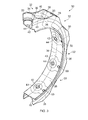
- the support cup 20 is one of a plurality of such cups, one for each blade 16, provided in a support ring 30 shown in Figure 3 . It will be appreciated that the support cups 20 are disposed in a circumferential array about the support ring 30 and are interconnected by bridging structures 32. The axis of the support ring 30 coincides with the engine axis X.
- Each support cup comprises a side wall 34 which is circular in cross-section.
- the interior surface of the side wall 34 is profiled in order to accommodate the bearings 22, 24, and the geometry of the side wall 34 is otherwise configured in order to provide adequate rigidity to support the blade 16 in a stable manner.
- Each bridging structure 32 has a generally channel-shaped cross-section, as viewed in a plane extending axially and radially with respect to the central axis of the support ring 30.
- Each bridging structure 32 thus comprises two axially spaced apart bridging walls 36 which extend radially outwardly from a bridging web 38.
- the side walls 34 of the support cups 20 extend fully between the bridging walls 36 and adjoin them.
- the bridging structures thus define "pockets" 39 which, like the support cups 20, are open at the radially outer face of the support ring 30.
- Each bridging wall 36 adjoins the side walls 34 of the support cups 20 at each circumferential end over the full radial depth of the support cups 20.
- the radially outer edges 40 of the bridging walls 36 are concavely curved, as viewed along the axis of the support ring 30, so that they have a "scalloped" form.
- each bridging structure 32 has a substantially straight neutral axis in the hoop direction and so behaves, in tension, like a straight strut.
- the support ring 30 is equivalent to a polygon, with the support cups 20 interconnected by straight links afforded by the bridging structures 32.
- Each support cup 20 has a radially inner end wall 42 provided with a central aperture 44 through which extends the pitch control shaft 26 ( Figure 2 ). It will be appreciated from Figures 2 and 3 that, in the region of the central aperture 44, the wall thickness of the radially inner end wall 42 is increased to reduce the hoop stress peak generated at the aperture 44.
- the radially inner end walls 42 of the support cups 20 lie in the same circumferential plane as the bridging webs 38 so as to provide a substantially continuous inner surface for the ring body constituted by the support cups 20 and the bridging structures 32.
- the support ring 30 is provided with a drive flange 46 which extends generally axially from the ring body constituted by the support cups 20 and the bridging structures 32.
- the drive flange 46 is bolted to the shaft assembly 12 to transmit rotation from the shaft assembly 12 to the propeller assembly 6, 8.
- an optional catcher drive arm 47 (which may take the form of any suitable member such as a flange), which extends axially (or alternatively radially) from the ring body and is coupled to the shaft assembly 12 by a clearance joint 49 which includes a nut and bolt assembly (not shown).
- the catcher drive arm 47 acts to strengthen the assembly and retains the support ring 30 in the event of a mechanical failure of the drive flange 46, for example.
- the clearance joint 49 avoids thermal fight with the shaft assembly, but offers a secondary load path in the event of failure of the first drive arm, or of the hub.
- the drive flange 46 provides a path for the conduction of heat from the exhaust gas flowing in the duct 10 to the ring body, and in particular to the bearings 22, 24.
- cooling air is directed, as indicated by arrows 48, between the support ring 30 and the shaft assembly 12.
- cooling holes 50 are provided in the drive flange 46 and, as shown in Figure 3 , these cooling holes may be positioned at the same angular locations as the support cups 20. The cooling holes 50 thus provide a thermal barrier to heat flow to the support cups 20.
- the outside profile of the bridging walls 36 follows the profile of the outer surface of the side walls 34 of the support cups 20. This provides surface continuity in the hoop direction. This exterior profile of the bridging walls 36 is followed on the interior surface of the bridging walls, in order to achieve an efficient side wall profile.
- the channel section ring 30 connects the full radial depth of the bearing support cups 20 for maximum hoop, and hoop bending, stiffness.
- the scalloping of the edges 40 of the bridging walls 36 turns a basic circular form into a polygonal ring, which is more efficient at carrying the dominant local blade loading.
- the radial inner end wall 42 provides a floor of the support cup 20 and so stiffens it efficiently, and minimises the hoop carrying material radius.
- the polygonised inter-cup floor provided by the bridging web 38 efficiently completes the hoop load path. At the bridging walls 36 the webs 38 may follow a circular profile, but transition to a straight profile in the central region to give a polygonised loadpath in the thin web 38.
- the open top form is compatible with the blade space requirements, and gives good machining and inspection access, whilst the relatively low torsional stiffness of a thin open channel section ring beam is enhanced by the channel section flexural centre being directed by the shear flows to a position radially inboard of the ring base, minimising the ring free torsional length.
- the drive flange 46 contributes to the torsional stiffness.
- the drive flange 46 thermally isolates the body of the ring 30 from the hot gas stream 14, enabling the ring 30 to be made in titanium alloy for low weight and low thermal expansion and good fatigue properties at the operating temperature. Other materials such as steel or aluminium could also be used with sufficient thermal isolation.
- the local reinforcement around the aperture 44 reduces peak stresses.
- the efficient hoop load paths and low density material for the ring 30 save significant weight.
- the thermal isolation provided by the drive flange 46 and the cooling air flow 48 minimises thermal fights which might otherwise arise owing to the close proximity of the hot gas stream. It also protects the bearings 22, 24, their lubrication, and the blade roots 18 (which may be made from a composite material), from excessive temperature.
- the radial depth of the support ring 30 enhances the hoop bending stiffness and therefore provides improved integrity in the event of blade failure or other extreme load conditions.
- the scalloping at the edges 40 could be reduced but made more effective by increasing the local axial length (i.e. thickness) of the bridging walls 36 in the region of the edges 40 . This would stiffen the rim under torsion, and under hoop bending.
- radial view X bracing could be introduced into the pockets 39 formed by the bridging structures 32, to triangulate the existing open rectangular space.
- the bracing webs may connect to the cups 20 between the bridging walls 36 for more even cup support.
- the support cups 20 themselves are stiffened by the transition material at their junctions with the bridging walls 36, and by the presence of the bearings 22, 24 and the blade root or hub 18, giving a cup circle radial load path under bearing preloading and blade load.
- a support ring as described with reference to Figures 2 and 3 could be employed in other propulsion unit configurations, such as “puller” units and turboprop engines.
- the principles underlying the present invention can be applied to any large diameter but radially shallow rotating hub structure with a relatively low blade count, such as a wind or water turbine, an aircraft or ship propeller or an office or air conditioning fan.
Landscapes
- Engineering & Computer Science (AREA)
- Aviation & Aerospace Engineering (AREA)
- Mechanical Engineering (AREA)
- General Engineering & Computer Science (AREA)
- Structures Of Non-Positive Displacement Pumps (AREA)
- Turbine Rotor Nozzle Sealing (AREA)
Applications Claiming Priority (1)
| Application Number | Priority Date | Filing Date | Title |
|---|---|---|---|
| GBGB1118386.0A GB201118386D0 (en) | 2011-10-25 | 2011-10-25 | A support ring for a rotary assembly |
Publications (3)
| Publication Number | Publication Date |
|---|---|
| EP2586701A2 true EP2586701A2 (de) | 2013-05-01 |
| EP2586701A3 EP2586701A3 (de) | 2017-11-08 |
| EP2586701B1 EP2586701B1 (de) | 2018-12-05 |
Family
ID=45373362
Family Applications (1)
| Application Number | Title | Priority Date | Filing Date |
|---|---|---|---|
| EP12188780.6A Active EP2586701B1 (de) | 2011-10-25 | 2012-10-17 | Stützring für eine Propelleranordnung |
Country Status (5)
| Country | Link |
|---|---|
| US (1) | US9039376B2 (de) |
| EP (1) | EP2586701B1 (de) |
| JP (1) | JP6074222B2 (de) |
| CA (1) | CA2792750A1 (de) |
| GB (1) | GB201118386D0 (de) |
Cited By (4)
| Publication number | Priority date | Publication date | Assignee | Title |
|---|---|---|---|---|
| EP2960151A1 (de) * | 2014-06-16 | 2015-12-30 | Rolls-Royce plc | Anordnung eines verstellrings |
| WO2016066977A1 (fr) | 2014-10-31 | 2016-05-06 | Snecma | Anneau d'hélice comprenant des logements radiaux de section ovoïde |
| FR3027948A1 (fr) * | 2014-10-31 | 2016-05-06 | Snecma | Anneau d'helice en materiau composite pour une turbomachine |
| US9890656B2 (en) | 2014-05-28 | 2018-02-13 | Rolls-Royce Deutschland Ltd & Co Kg | Variable stator vane arrangement |
Families Citing this family (9)
| Publication number | Priority date | Publication date | Assignee | Title |
|---|---|---|---|---|
| FR3021295B1 (fr) * | 2014-05-21 | 2016-05-13 | Snecma | Moyeu raidi pour helice non carenee a pales a calage variable de turbomachine. |
| FR3025247B1 (fr) * | 2014-08-29 | 2016-11-11 | Snecma | Roue aubagee a calages variables |
| US10819182B2 (en) | 2017-01-09 | 2020-10-27 | Ge Aviation Systems Llc | Stator support for an electric machine |
| US10738630B2 (en) | 2018-02-19 | 2020-08-11 | General Electric Company | Platform apparatus for propulsion rotor |
| US11391179B2 (en) | 2019-02-12 | 2022-07-19 | Pratt & Whitney Canada Corp. | Gas turbine engine with bearing support structure |
| US11346249B2 (en) | 2019-03-05 | 2022-05-31 | Pratt & Whitney Canada Corp. | Gas turbine engine with feed pipe for bearing housing |
| US11460037B2 (en) | 2019-03-29 | 2022-10-04 | Pratt & Whitney Canada Corp. | Bearing housing |
| US12247516B2 (en) | 2022-09-29 | 2025-03-11 | General Electric Company | Counter-rotating gas turbine engines including turbine sections with separable torque frames |
| FR3152834B1 (fr) * | 2023-09-13 | 2025-08-15 | Safran Aircraft Engines | Moyeu de soufflante assemblé par soudage par friction |
Citations (1)
| Publication number | Priority date | Publication date | Assignee | Title |
|---|---|---|---|---|
| WO2011000943A1 (fr) | 2009-07-02 | 2011-01-06 | Snecma | Moyeu d'helice |
Family Cites Families (15)
| Publication number | Priority date | Publication date | Assignee | Title |
|---|---|---|---|---|
| GB1195961A (en) | 1966-12-05 | 1970-06-24 | Rolls Royce | Variable Pitch Aerofoil Blades. |
| US4082378A (en) | 1975-07-14 | 1978-04-04 | General Electric Company | Deformable bearing seat |
| DE2856099B1 (de) | 1978-12-23 | 1980-04-30 | Kloeckner-Werke Ag, 4100 Duisburg | Kettenrad mit Kettentaschen |
| US4863352A (en) * | 1984-11-02 | 1989-09-05 | General Electric Company | Blade carrying means |
| FR2605586B1 (fr) * | 1986-10-22 | 1990-11-30 | Snecma | Anneau porte-pales pour aubage d'helice de grande dimension |
| US5108259A (en) * | 1988-12-19 | 1992-04-28 | General Electric Company | Flexible connector for use in aircraft |
| JPH02246897A (ja) * | 1988-12-29 | 1990-10-02 | General Electric Co <Ge> | 航空機推進装置及び方法 |
| US5082424A (en) * | 1989-06-05 | 1992-01-21 | General Electric Company | Connection system for aircraft propeller blades |
| FR2666623B1 (fr) | 1990-09-11 | 1993-05-07 | Turbomeca | Roue de turbomachine a pales rapportees. |
| EP1319805A1 (de) | 2001-12-17 | 2003-06-18 | Techspace aero | Rotor oder Rototelement für Turbokompressoren |
| US20100190596A1 (en) | 2009-01-27 | 2010-07-29 | Norman Wills | Quiet Sprocket Device |
| FR2943312B1 (fr) * | 2009-03-23 | 2011-05-27 | Snecma | Helice non carenee a pales a calage variable pour une turbomachine |
| FR2951435B1 (fr) * | 2009-10-15 | 2012-02-03 | Snecma | Dispositif adapte pour etre pourvu de pales d'helice |
| JP5732067B2 (ja) | 2009-12-07 | 2015-06-10 | スネクマ | 補強された多角形リングを有するプロペラハブおよびこの種のハブが設けられるタービンエンジン |
| FR2953486B1 (fr) | 2009-12-07 | 2011-11-18 | Snecma | Moyeu d'helice a anneau polygonal plein et turbomachine equipee d'un tel moyeu |
-
2011
- 2011-10-25 GB GBGB1118386.0A patent/GB201118386D0/en not_active Ceased
-
2012
- 2012-10-17 CA CA2792750A patent/CA2792750A1/en not_active Abandoned
- 2012-10-17 US US13/653,780 patent/US9039376B2/en active Active
- 2012-10-17 EP EP12188780.6A patent/EP2586701B1/de active Active
- 2012-10-24 JP JP2012234696A patent/JP6074222B2/ja active Active
Patent Citations (1)
| Publication number | Priority date | Publication date | Assignee | Title |
|---|---|---|---|---|
| WO2011000943A1 (fr) | 2009-07-02 | 2011-01-06 | Snecma | Moyeu d'helice |
Cited By (9)
| Publication number | Priority date | Publication date | Assignee | Title |
|---|---|---|---|---|
| US9890656B2 (en) | 2014-05-28 | 2018-02-13 | Rolls-Royce Deutschland Ltd & Co Kg | Variable stator vane arrangement |
| EP2960151A1 (de) * | 2014-06-16 | 2015-12-30 | Rolls-Royce plc | Anordnung eines verstellrings |
| WO2016066977A1 (fr) | 2014-10-31 | 2016-05-06 | Snecma | Anneau d'hélice comprenant des logements radiaux de section ovoïde |
| FR3027948A1 (fr) * | 2014-10-31 | 2016-05-06 | Snecma | Anneau d'helice en materiau composite pour une turbomachine |
| FR3027947A1 (fr) * | 2014-10-31 | 2016-05-06 | Snecma | Anneau d'helice comprenant des logements radiaux de section ovoide |
| GB2547169A (en) * | 2014-10-31 | 2017-08-09 | Safran Aircraft Engines | Propeller ring comprising radial housings with an ovoid cross-section |
| US10378368B2 (en) | 2014-10-31 | 2019-08-13 | Safran Aircraft Engines | Propeller ring made of composite material for a turbomachine |
| US10526067B2 (en) | 2014-10-31 | 2020-01-07 | Safran Aircraft Engines | Propeller ring comprising radial housings with an ovoid cross-section |
| GB2547169B (en) * | 2014-10-31 | 2020-07-29 | Safran Aircraft Engines | Propeller ring comprising radial housings with an ovoid cross-section |
Also Published As
| Publication number | Publication date |
|---|---|
| CA2792750A1 (en) | 2013-04-25 |
| JP6074222B2 (ja) | 2017-02-01 |
| EP2586701B1 (de) | 2018-12-05 |
| US9039376B2 (en) | 2015-05-26 |
| US20130101434A1 (en) | 2013-04-25 |
| JP2013091490A (ja) | 2013-05-16 |
| EP2586701A3 (de) | 2017-11-08 |
| GB201118386D0 (en) | 2011-12-07 |
Similar Documents
| Publication | Publication Date | Title |
|---|---|---|
| US9039376B2 (en) | Support ring for a rotary assembly | |
| EP2589461B1 (de) | Laufschaufel mit geklebter Abdeckung | |
| US8312726B2 (en) | Gas turbine engine systems involving I-beam struts | |
| EP1882827B1 (de) | Eingebetteter Träger für einen Mittelturbinenrahmen | |
| US9303531B2 (en) | Quick engine change assembly for outlet guide vanes | |
| US9303520B2 (en) | Double fan outlet guide vane with structural platforms | |
| US6371725B1 (en) | Conforming platform guide vane | |
| EP2788587B1 (de) | Körper einer Lüfternabe | |
| EP1857639A2 (de) | Rahmen eines Fanrotors | |
| EP2333251A2 (de) | Fan-Berstschutzring | |
| CN117715824A (zh) | 用于飞行器的推进装置 | |
| US8801378B2 (en) | Low offset hingeless rotor with pitch change bearings | |
| EP2366871B1 (de) | Verfahren und Vorrichtung für eine strukturelle Auslassleitschaufel | |
| CN116209821B (zh) | 设置有螺旋桨和偏置定子轮叶的涡轮机模块 | |
| US9255583B2 (en) | Propeller hub having a reinforced polygonal ring and turbine engine provided with such a hub | |
| US20220316574A1 (en) | Gear wheel | |
| US20130019609A1 (en) | Gas turbine engine systems involving i-beam struts | |
| US10793264B2 (en) | Flex beam clamp for rotor assembly | |
| EP4361403A1 (de) | Leitungsdurchführung mit zellmaterial | |
| US20100074778A1 (en) | Closed-circuit hydraulic propeller | |
| US12378889B2 (en) | Turbine engine with a blade assembly having cooling conduits | |
| EP2369134A1 (de) | Turbinenschaufel mit Hohlraeumen zur Gewichts- und Vibrationsreduzierung | |
| GB2640541A (en) | Mount arrangement |
Legal Events
| Date | Code | Title | Description |
|---|---|---|---|
| PUAI | Public reference made under article 153(3) epc to a published international application that has entered the european phase |
Free format text: ORIGINAL CODE: 0009012 |
|
| AK | Designated contracting states |
Kind code of ref document: A2 Designated state(s): AL AT BE BG CH CY CZ DE DK EE ES FI FR GB GR HR HU IE IS IT LI LT LU LV MC MK MT NL NO PL PT RO RS SE SI SK SM TR |
|
| AX | Request for extension of the european patent |
Extension state: BA ME |
|
| RAP1 | Party data changed (applicant data changed or rights of an application transferred) |
Owner name: ROLLS-ROYCE PLC |
|
| PUAL | Search report despatched |
Free format text: ORIGINAL CODE: 0009013 |
|
| AK | Designated contracting states |
Kind code of ref document: A3 Designated state(s): AL AT BE BG CH CY CZ DE DK EE ES FI FR GB GR HR HU IE IS IT LI LT LU LV MC MK MT NL NO PL PT RO RS SE SI SK SM TR |
|
| AX | Request for extension of the european patent |
Extension state: BA ME |
|
| RIC1 | Information provided on ipc code assigned before grant |
Ipc: B64C 11/06 20060101AFI20171004BHEP |
|
| STAA | Information on the status of an ep patent application or granted ep patent |
Free format text: STATUS: REQUEST FOR EXAMINATION WAS MADE |
|
| 17P | Request for examination filed |
Effective date: 20180430 |
|
| RBV | Designated contracting states (corrected) |
Designated state(s): AL AT BE BG CH CY CZ DE DK EE ES FI FR GB GR HR HU IE IS IT LI LT LU LV MC MK MT NL NO PL PT RO RS SE SI SK SM TR |
|
| GRAP | Despatch of communication of intention to grant a patent |
Free format text: ORIGINAL CODE: EPIDOSNIGR1 |
|
| STAA | Information on the status of an ep patent application or granted ep patent |
Free format text: STATUS: GRANT OF PATENT IS INTENDED |
|
| GRAS | Grant fee paid |
Free format text: ORIGINAL CODE: EPIDOSNIGR3 |
|
| INTG | Intention to grant announced |
Effective date: 20180912 |
|
| GRAA | (expected) grant |
Free format text: ORIGINAL CODE: 0009210 |
|
| GRAA | (expected) grant |
Free format text: ORIGINAL CODE: 0009210 |
|
| STAA | Information on the status of an ep patent application or granted ep patent |
Free format text: STATUS: THE PATENT HAS BEEN GRANTED |
|
| AK | Designated contracting states |
Kind code of ref document: B1 Designated state(s): AL AT BE BG CH CY CZ DE DK EE ES FI FR GB GR HR HU IE IS IT LI LT LU LV MC MK MT NL NO PL PT RO RS SE SI SK SM TR |
|
| REG | Reference to a national code |
Ref country code: GB Ref legal event code: FG4D |
|
| REG | Reference to a national code |
Ref country code: CH Ref legal event code: EP |
|
| REG | Reference to a national code |
Ref country code: AT Ref legal event code: REF Ref document number: 1072703 Country of ref document: AT Kind code of ref document: T Effective date: 20181215 |
|
| REG | Reference to a national code |
Ref country code: IE Ref legal event code: FG4D |
|
| REG | Reference to a national code |
Ref country code: DE Ref legal event code: R096 Ref document number: 602012054283 Country of ref document: DE |
|
| REG | Reference to a national code |
Ref country code: NL Ref legal event code: MP Effective date: 20181205 |
|
| REG | Reference to a national code |
Ref country code: AT Ref legal event code: MK05 Ref document number: 1072703 Country of ref document: AT Kind code of ref document: T Effective date: 20181205 |
|
| REG | Reference to a national code |
Ref country code: LT Ref legal event code: MG4D |
|
| PG25 | Lapsed in a contracting state [announced via postgrant information from national office to epo] |
Ref country code: LV Free format text: LAPSE BECAUSE OF FAILURE TO SUBMIT A TRANSLATION OF THE DESCRIPTION OR TO PAY THE FEE WITHIN THE PRESCRIBED TIME-LIMIT Effective date: 20181205 Ref country code: HR Free format text: LAPSE BECAUSE OF FAILURE TO SUBMIT A TRANSLATION OF THE DESCRIPTION OR TO PAY THE FEE WITHIN THE PRESCRIBED TIME-LIMIT Effective date: 20181205 Ref country code: AT Free format text: LAPSE BECAUSE OF FAILURE TO SUBMIT A TRANSLATION OF THE DESCRIPTION OR TO PAY THE FEE WITHIN THE PRESCRIBED TIME-LIMIT Effective date: 20181205 Ref country code: LT Free format text: LAPSE BECAUSE OF FAILURE TO SUBMIT A TRANSLATION OF THE DESCRIPTION OR TO PAY THE FEE WITHIN THE PRESCRIBED TIME-LIMIT Effective date: 20181205 Ref country code: BG Free format text: LAPSE BECAUSE OF FAILURE TO SUBMIT A TRANSLATION OF THE DESCRIPTION OR TO PAY THE FEE WITHIN THE PRESCRIBED TIME-LIMIT Effective date: 20190305 Ref country code: NO Free format text: LAPSE BECAUSE OF FAILURE TO SUBMIT A TRANSLATION OF THE DESCRIPTION OR TO PAY THE FEE WITHIN THE PRESCRIBED TIME-LIMIT Effective date: 20190305 Ref country code: ES Free format text: LAPSE BECAUSE OF FAILURE TO SUBMIT A TRANSLATION OF THE DESCRIPTION OR TO PAY THE FEE WITHIN THE PRESCRIBED TIME-LIMIT Effective date: 20181205 Ref country code: FI Free format text: LAPSE BECAUSE OF FAILURE TO SUBMIT A TRANSLATION OF THE DESCRIPTION OR TO PAY THE FEE WITHIN THE PRESCRIBED TIME-LIMIT Effective date: 20181205 |
|
| PG25 | Lapsed in a contracting state [announced via postgrant information from national office to epo] |
Ref country code: GR Free format text: LAPSE BECAUSE OF FAILURE TO SUBMIT A TRANSLATION OF THE DESCRIPTION OR TO PAY THE FEE WITHIN THE PRESCRIBED TIME-LIMIT Effective date: 20190306 Ref country code: RS Free format text: LAPSE BECAUSE OF FAILURE TO SUBMIT A TRANSLATION OF THE DESCRIPTION OR TO PAY THE FEE WITHIN THE PRESCRIBED TIME-LIMIT Effective date: 20181205 Ref country code: SE Free format text: LAPSE BECAUSE OF FAILURE TO SUBMIT A TRANSLATION OF THE DESCRIPTION OR TO PAY THE FEE WITHIN THE PRESCRIBED TIME-LIMIT Effective date: 20181205 Ref country code: AL Free format text: LAPSE BECAUSE OF FAILURE TO SUBMIT A TRANSLATION OF THE DESCRIPTION OR TO PAY THE FEE WITHIN THE PRESCRIBED TIME-LIMIT Effective date: 20181205 |
|
| PG25 | Lapsed in a contracting state [announced via postgrant information from national office to epo] |
Ref country code: NL Free format text: LAPSE BECAUSE OF FAILURE TO SUBMIT A TRANSLATION OF THE DESCRIPTION OR TO PAY THE FEE WITHIN THE PRESCRIBED TIME-LIMIT Effective date: 20181205 |
|
| PG25 | Lapsed in a contracting state [announced via postgrant information from national office to epo] |
Ref country code: PL Free format text: LAPSE BECAUSE OF FAILURE TO SUBMIT A TRANSLATION OF THE DESCRIPTION OR TO PAY THE FEE WITHIN THE PRESCRIBED TIME-LIMIT Effective date: 20181205 Ref country code: IT Free format text: LAPSE BECAUSE OF FAILURE TO SUBMIT A TRANSLATION OF THE DESCRIPTION OR TO PAY THE FEE WITHIN THE PRESCRIBED TIME-LIMIT Effective date: 20181205 Ref country code: PT Free format text: LAPSE BECAUSE OF FAILURE TO SUBMIT A TRANSLATION OF THE DESCRIPTION OR TO PAY THE FEE WITHIN THE PRESCRIBED TIME-LIMIT Effective date: 20190405 Ref country code: CZ Free format text: LAPSE BECAUSE OF FAILURE TO SUBMIT A TRANSLATION OF THE DESCRIPTION OR TO PAY THE FEE WITHIN THE PRESCRIBED TIME-LIMIT Effective date: 20181205 |
|
| PG25 | Lapsed in a contracting state [announced via postgrant information from national office to epo] |
Ref country code: RO Free format text: LAPSE BECAUSE OF FAILURE TO SUBMIT A TRANSLATION OF THE DESCRIPTION OR TO PAY THE FEE WITHIN THE PRESCRIBED TIME-LIMIT Effective date: 20181205 Ref country code: SK Free format text: LAPSE BECAUSE OF FAILURE TO SUBMIT A TRANSLATION OF THE DESCRIPTION OR TO PAY THE FEE WITHIN THE PRESCRIBED TIME-LIMIT Effective date: 20181205 Ref country code: IS Free format text: LAPSE BECAUSE OF FAILURE TO SUBMIT A TRANSLATION OF THE DESCRIPTION OR TO PAY THE FEE WITHIN THE PRESCRIBED TIME-LIMIT Effective date: 20190405 Ref country code: EE Free format text: LAPSE BECAUSE OF FAILURE TO SUBMIT A TRANSLATION OF THE DESCRIPTION OR TO PAY THE FEE WITHIN THE PRESCRIBED TIME-LIMIT Effective date: 20181205 Ref country code: SM Free format text: LAPSE BECAUSE OF FAILURE TO SUBMIT A TRANSLATION OF THE DESCRIPTION OR TO PAY THE FEE WITHIN THE PRESCRIBED TIME-LIMIT Effective date: 20181205 |
|
| REG | Reference to a national code |
Ref country code: DE Ref legal event code: R097 Ref document number: 602012054283 Country of ref document: DE |
|
| PLBE | No opposition filed within time limit |
Free format text: ORIGINAL CODE: 0009261 |
|
| STAA | Information on the status of an ep patent application or granted ep patent |
Free format text: STATUS: NO OPPOSITION FILED WITHIN TIME LIMIT |
|
| PG25 | Lapsed in a contracting state [announced via postgrant information from national office to epo] |
Ref country code: SI Free format text: LAPSE BECAUSE OF FAILURE TO SUBMIT A TRANSLATION OF THE DESCRIPTION OR TO PAY THE FEE WITHIN THE PRESCRIBED TIME-LIMIT Effective date: 20181205 Ref country code: DK Free format text: LAPSE BECAUSE OF FAILURE TO SUBMIT A TRANSLATION OF THE DESCRIPTION OR TO PAY THE FEE WITHIN THE PRESCRIBED TIME-LIMIT Effective date: 20181205 |
|
| 26N | No opposition filed |
Effective date: 20190906 |
|
| PG25 | Lapsed in a contracting state [announced via postgrant information from national office to epo] |
Ref country code: TR Free format text: LAPSE BECAUSE OF FAILURE TO SUBMIT A TRANSLATION OF THE DESCRIPTION OR TO PAY THE FEE WITHIN THE PRESCRIBED TIME-LIMIT Effective date: 20181205 |
|
| PG25 | Lapsed in a contracting state [announced via postgrant information from national office to epo] |
Ref country code: MC Free format text: LAPSE BECAUSE OF FAILURE TO SUBMIT A TRANSLATION OF THE DESCRIPTION OR TO PAY THE FEE WITHIN THE PRESCRIBED TIME-LIMIT Effective date: 20181205 |
|
| REG | Reference to a national code |
Ref country code: CH Ref legal event code: PL |
|
| PG25 | Lapsed in a contracting state [announced via postgrant information from national office to epo] |
Ref country code: LU Free format text: LAPSE BECAUSE OF NON-PAYMENT OF DUE FEES Effective date: 20191017 Ref country code: CH Free format text: LAPSE BECAUSE OF NON-PAYMENT OF DUE FEES Effective date: 20191031 Ref country code: LI Free format text: LAPSE BECAUSE OF NON-PAYMENT OF DUE FEES Effective date: 20191031 |
|
| REG | Reference to a national code |
Ref country code: BE Ref legal event code: MM Effective date: 20191031 |
|
| PG25 | Lapsed in a contracting state [announced via postgrant information from national office to epo] |
Ref country code: BE Free format text: LAPSE BECAUSE OF NON-PAYMENT OF DUE FEES Effective date: 20191031 |
|
| PG25 | Lapsed in a contracting state [announced via postgrant information from national office to epo] |
Ref country code: IE Free format text: LAPSE BECAUSE OF NON-PAYMENT OF DUE FEES Effective date: 20191017 |
|
| PG25 | Lapsed in a contracting state [announced via postgrant information from national office to epo] |
Ref country code: CY Free format text: LAPSE BECAUSE OF FAILURE TO SUBMIT A TRANSLATION OF THE DESCRIPTION OR TO PAY THE FEE WITHIN THE PRESCRIBED TIME-LIMIT Effective date: 20181205 |
|
| PG25 | Lapsed in a contracting state [announced via postgrant information from national office to epo] |
Ref country code: MT Free format text: LAPSE BECAUSE OF FAILURE TO SUBMIT A TRANSLATION OF THE DESCRIPTION OR TO PAY THE FEE WITHIN THE PRESCRIBED TIME-LIMIT Effective date: 20181205 Ref country code: HU Free format text: LAPSE BECAUSE OF FAILURE TO SUBMIT A TRANSLATION OF THE DESCRIPTION OR TO PAY THE FEE WITHIN THE PRESCRIBED TIME-LIMIT; INVALID AB INITIO Effective date: 20121017 |
|
| PG25 | Lapsed in a contracting state [announced via postgrant information from national office to epo] |
Ref country code: MK Free format text: LAPSE BECAUSE OF FAILURE TO SUBMIT A TRANSLATION OF THE DESCRIPTION OR TO PAY THE FEE WITHIN THE PRESCRIBED TIME-LIMIT Effective date: 20181205 |
|
| P01 | Opt-out of the competence of the unified patent court (upc) registered |
Effective date: 20230528 |
|
| PGFP | Annual fee paid to national office [announced via postgrant information from national office to epo] |
Ref country code: DE Payment date: 20251028 Year of fee payment: 14 |
|
| PGFP | Annual fee paid to national office [announced via postgrant information from national office to epo] |
Ref country code: GB Payment date: 20251023 Year of fee payment: 14 |
|
| PGFP | Annual fee paid to national office [announced via postgrant information from national office to epo] |
Ref country code: FR Payment date: 20251027 Year of fee payment: 14 |