EP2586719B1 - Unité de pliage et procédé de production de paquets de produits alimentaires pouvant être versés - Google Patents
Unité de pliage et procédé de production de paquets de produits alimentaires pouvant être versés Download PDFInfo
- Publication number
- EP2586719B1 EP2586719B1 EP11187356.8A EP11187356A EP2586719B1 EP 2586719 B1 EP2586719 B1 EP 2586719B1 EP 11187356 A EP11187356 A EP 11187356A EP 2586719 B1 EP2586719 B1 EP 2586719B1
- Authority
- EP
- European Patent Office
- Prior art keywords
- along
- shells
- relative
- pack
- closed position
- Prior art date
- Legal status (The legal status is an assumption and is not a legal conclusion. Google has not performed a legal analysis and makes no representation as to the accuracy of the status listed.)
- Active
Links
Images



Classifications
-
- B—PERFORMING OPERATIONS; TRANSPORTING
- B31—MAKING ARTICLES OF PAPER, CARDBOARD OR MATERIAL WORKED IN A MANNER ANALOGOUS TO PAPER; WORKING PAPER, CARDBOARD OR MATERIAL WORKED IN A MANNER ANALOGOUS TO PAPER
- B31B—MAKING CONTAINERS OF PAPER, CARDBOARD OR MATERIAL WORKED IN A MANNER ANALOGOUS TO PAPER
- B31B50/00—Making rigid or semi-rigid containers, e.g. boxes or cartons
- B31B50/26—Folding sheets, blanks or webs
-
- B—PERFORMING OPERATIONS; TRANSPORTING
- B65—CONVEYING; PACKING; STORING; HANDLING THIN OR FILAMENTARY MATERIAL
- B65B—MACHINES, APPARATUS OR DEVICES FOR, OR METHODS OF, PACKAGING ARTICLES OR MATERIALS; UNPACKING
- B65B61/00—Auxiliary devices, not otherwise provided for, for operating on sheets, blanks, webs, binding material, containers or packages
- B65B61/24—Auxiliary devices, not otherwise provided for, for operating on sheets, blanks, webs, binding material, containers or packages for shaping or reshaping completed packages
-
- B—PERFORMING OPERATIONS; TRANSPORTING
- B31—MAKING ARTICLES OF PAPER, CARDBOARD OR MATERIAL WORKED IN A MANNER ANALOGOUS TO PAPER; WORKING PAPER, CARDBOARD OR MATERIAL WORKED IN A MANNER ANALOGOUS TO PAPER
- B31B—MAKING CONTAINERS OF PAPER, CARDBOARD OR MATERIAL WORKED IN A MANNER ANALOGOUS TO PAPER
- B31B50/00—Making rigid or semi-rigid containers, e.g. boxes or cartons
- B31B50/26—Folding sheets, blanks or webs
- B31B50/52—Folding sheets, blanks or webs by reciprocating or oscillating members, e.g. fingers
-
- B—PERFORMING OPERATIONS; TRANSPORTING
- B65—CONVEYING; PACKING; STORING; HANDLING THIN OR FILAMENTARY MATERIAL
- B65B—MACHINES, APPARATUS OR DEVICES FOR, OR METHODS OF, PACKAGING ARTICLES OR MATERIALS; UNPACKING
- B65B49/00—Devices for folding or bending wrappers around contents
- B65B49/02—Fixed or resiliently-mounted folders, e.g. non-driven rollers
- B65B49/04—Ploughs or plates with inclined slots or opposed inclined edges
-
- B—PERFORMING OPERATIONS; TRANSPORTING
- B65—CONVEYING; PACKING; STORING; HANDLING THIN OR FILAMENTARY MATERIAL
- B65B—MACHINES, APPARATUS OR DEVICES FOR, OR METHODS OF, PACKAGING ARTICLES OR MATERIALS; UNPACKING
- B65B49/00—Devices for folding or bending wrappers around contents
- B65B49/08—Reciprocating or oscillating folders
-
- B—PERFORMING OPERATIONS; TRANSPORTING
- B65—CONVEYING; PACKING; STORING; HANDLING THIN OR FILAMENTARY MATERIAL
- B65B—MACHINES, APPARATUS OR DEVICES FOR, OR METHODS OF, PACKAGING ARTICLES OR MATERIALS; UNPACKING
- B65B49/00—Devices for folding or bending wrappers around contents
- B65B49/14—Folders forming part of, or attached to, conveyors for partially-wrapped articles
-
- B—PERFORMING OPERATIONS; TRANSPORTING
- B65—CONVEYING; PACKING; STORING; HANDLING THIN OR FILAMENTARY MATERIAL
- B65B—MACHINES, APPARATUS OR DEVICES FOR, OR METHODS OF, PACKAGING ARTICLES OR MATERIALS; UNPACKING
- B65B9/00—Enclosing successive articles, or quantities of material, e.g. liquids or semiliquids, in flat, folded, or tubular webs of flexible sheet material; Subdividing filled flexible tubes to form packages
- B65B9/10—Enclosing successive articles, or quantities of material, in preformed tubular webs, or in webs formed into tubes around filling nozzles, e.g. extruded tubular webs
- B65B9/20—Enclosing successive articles, or quantities of material, in preformed tubular webs, or in webs formed into tubes around filling nozzles, e.g. extruded tubular webs the webs being formed into tubes in situ around the filling nozzles
Definitions
- the present invention relates to a folding unit and to a method for producing folded packages of pourable food products from relative sealed packs.
- Tetra Brik Aseptic registered trademark
- a typical example of this type of package is the parallelepiped-shaped package for liquid or pourable food products known as Tetra Brik Aseptic (registered trademark), which is made by folding and sealing laminated strip packaging material.
- the packaging material has a multilayer structure substantially comprising a base layer for stiffness and strength, which may comprise a layer of fibrous material, e.g. paper, or of mineral-filled polypropylene material; and a number of layers of heat-seal plastic material, e.g. polyethylene film, covering both sides of the base layer.
- a base layer for stiffness and strength may comprise a layer of fibrous material, e.g. paper, or of mineral-filled polypropylene material; and a number of layers of heat-seal plastic material, e.g. polyethylene film, covering both sides of the base layer.
- the packaging material may also comprise a layer of gas- and light-barrier material, e.g. an aluminium foil or an ethyl vinyl alcohol (EVOH) foil, which is superimposed on a layer of heat-seal plastic material, and is in turn covered with another layer of heat-seal plastic material forming the inner face of the package eventually contacting the food product.
- gas- and light-barrier material e.g. an aluminium foil or an ethyl vinyl alcohol (EVOH) foil
- packages of this sort are produced on fully automatic packaging machines, on which a continuous tube is formed from the web-fed packaging material.
- the web of packaging material is sterilized on the packaging machine, e.g. by applying a chemical sterilizing agent, such as a hydrogen peroxide solution, which, once sterilization is completed, is removed from the surfaces of the packaging material, e.g. evaporated by heating.
- a chemical sterilizing agent such as a hydrogen peroxide solution
- the tube is filled continuously downwards with the sterilized or sterile-processed food product, and is sealed and then cut along equally spaced cross sections to form pillow packs, which may be fed to a folding unit to form the finished packages.
- the pillow packs substantially comprise a main portion, and opposite top and bottom end portions tapering from the main portions towards respective top and bottom sealing bands which extend substantially orthogonal to the axis of the pack.
- each end portion is defined by a pair of respective trapezoidal walls which extend between main portion of the pack and the relative sealing band.
- Each pillow pack also comprises, for each top and bottom end portion, an elongated substantially rectangular fin projecting from respective sealing bands; and a pair of substantially triangular flaps projecting from opposite sides of relative end portion and defined by respective trapezoidal walls.
- the end portions are pressed towards each other by the folding unit to form flat opposite end walls of the pack, while at the same time folding the flaps of the top portion onto respective lateral walls of the main portion and the flaps of the bottom portion onto the bottom sealing band.
- Packaging machines for producing packages of the above type are known, substantially comprising:
- Folding units are known, for example from EP-B-0887261 in the name of the same Applicant, which typically comprise:
- the chain conveyor comprises a top straight branch, a bottom straight branch and two curved portions which are opposite to each other and connect, on respective opposite sides, the top and bottom branches.
- the axes of the packs are slightly backwards inclined relative to a vertical direction when they are fed to the chain conveyor at the supply station, and are substantially vertical when packs are fed along the top branch. Furthermore, the folded packages are slightly forwards inclined relative to the vertical direction, when they reach the output station.
- the packs and the corresponding folded packages are arranged above and are, therefore, continuously supported by the chain conveyor.
- the pressing device comprises three endless belts which define, between them and together with the top branch of the chain, a forming passage having a constant rectangular section, and defining the outer contour of the finished packages.
- Transfer units are known, for example from EP-B-0887268 in the name of the same Applicant.
- the known transfer units move the packages successively along a path from an in-feed station to an out-feed station, and simultaneously up-end the packages from an in-feed position, in which the packages are positioned with their axis tilted roughly 15° to the horizontal, into an out-feed position, in which the packages are positioned with their axis substantially vertical.
- the in-feed position of the transfer unit substantially coincides with the output station of the folding unit.
- Known transfer units substantially comprise a rotary member having a number of push arms which cooperate with respective packages to push them along the path; and a fixed guide which extends along this path and cooperates with the packages to ease them from the tilted in-feed position to the out-feed position.
- the Applicant has found that the forming operation may require some adjustments. This is mainly due to the fact that the forming passage must be, in this case, polygonal whereas the endless belts have substantially flat surfaces cooperating with the folded package.
- DE-U-1913258 discloses a folding unit according to the preamble of claim 1.
- a folding unit for producing folded packages of pourable food products from relative sealed packs, as claimed in claim 1.
- the present invention also relates to a method for producing folded packages of pourable food product from relative sealed packs, as claimed in claim 9.
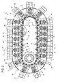
- Number 1 in Figure 1 indicates as a whole a folding unit for a packaging machine (not shown) for continuously producing sealed packages 2 of a pourable food product, such as pasteurized or UHT milk, fruit juice, wine, etc., from a known tube of packaging material (not shown).
- a packaging machine not shown
- sealed packages 2 of a pourable food product such as pasteurized or UHT milk, fruit juice, wine, etc.
- the tube is formed in known manner upstream from unit 1 by longitudinally folding and sealing a known web (not shown) of heat-seal sheet material, which may comprise a base layer for stiffness and strength, which may be formed by a layer of fibrous material, e.g. paper, or of mineral-filled polypropylene material, and a number of layers of heat-seal plastic material, e.g. polyethylene film, covering both sides of the base layer.
- the packaging material may also comprises a layer of gas- and light-barrier material, e.g.
- an aluminium foil or an ethyl vinyl alcohol (EVOH) foil which is superimposed on a layer of heat-seal plastic material, and is in turn covered with another layer of heat-seal plastic material forming the inner face of the package 2 eventually contacting the food product.
- EVOH ethyl vinyl alcohol
- the tube of packaging material is then filled with the food product for packaging, and is sealed and cut along equally spaced cross sections to form a number of pillow packs 3 ( Figure 15 ), which are then transferred to unit 1 where they are folded mechanically to form respective packages 2.
- the packaging material may be cut into blanks, which are formed into packages 2 with forming spindles, and packages 2 are filled with the food product and sealed.
- packages 2 are filled with the food product and sealed.
- Tetra Rex registered trademark
- pillow packs 3 are transferred to unit 1 by using an in-feed conveyor 41 ( Figure 1 ), which is described in more detail in the European application “Feeding unit and method for feeding sealed pillow packs of pourable food products to a folding unit", filed by the Applicant concurrently with the present invention.
- Unit 1 also feeds folded package 2 to out-feed conveyor 42, shown in Figure 1 .
- a package 2 which has a longitudinal sealing band 4, formed to produce the tube of packaging material from the web folded into a cylinder, extends along one side of each pack 3, which is closed at the opposite ends by respective transverse sealing bands 5, 6 perpendicular to and joined to longitudinal sealing band 4.
- Each pack 3 has an axis A, and comprises a main body 7 and opposite, respectively top and bottom, end portions 8, 9 tapering from main body 7 towards respective transverse sealing bands 5, 6.
- Main body 7 of each pack 3 is bounded laterally by four lateral walls 10a, 10b and four corner walls 11 alternate to each other, in the embodiment shown in Figure 15 .
- Walls 10a (10b) are opposite to each other. In the very same way, walls 11 are opposite, in pairs, to each other.
- Each wall 10a, 10b comprises a central rectangular stretch 13 and a pair of opposite, respective top and bottom, end stretches 14 which are interposed between stretch 13 and end portions 8, 9 of pack 3.
- stretches 13 are substantially parallel to axis A.
- Each end stretch 14 is substantially in the form of an isosceles trapezium, which slopes slightly relative to axis A, and has a major edge defined by respective end portions 8, 9.
- Each wall 11 comprises a central rectangular stretch 15 and a pair opposite, respective top and bottom, end stretches 16 which are interposed between stretch 15 and end portions 8, 9 of pack 3.
- stretches 15 are substantially parallel to axis A.
- Each end stretch 16 is substantially in the form of an isosceles triangle, which slopes slightly relative to axis A and converges from relative stretch 15 towards corresponding end portions 8, 9.
- Each end portion 8, 9 is defined by two walls 12, each substantially in the form of an isosceles trapezium, which slope slightly towards each other with respect to a plane perpendicular to axis A, and have minor edges defined by respective end edges of portions 14 of respective wall 10a, and major edges joined to each other by respective sealing bands 5, 6.
- Longitudinal sealing band 4 extends between transverse sealing bands 5 and 6, and along the whole of one wall 10a and the corresponding walls 12 on the same side as wall 10a.
- Each pack 3 also comprises, for each end portion 8, 9, a respective substantially elongated rectangular end fin 17, 18 projecting in the direction of axis A from relative pack 3; and two substantially triangular flaps 19, 20 projecting laterally on opposite sides of main body 7 and defined by end portions of relative walls 12.
- each end fin 17, 18 extends along a direction orthogonal to axis A.
- unit 1 presses end portions 8, 9 of relative pack 3 down flat towards each other, and at the same time folds respective fins 17, 18 onto end portions 8, 9.
- unit 1 folds flaps 20 onto top stretches 14 of respective walls 10b and folds flaps 19 onto previously folded fin 17, on the opposite side of end portion 9.
- unit 1 substantially comprises:
- Heating device 27 is, in particular, arranged between folding means 23 and pressure device 28 along forming path B.
- conveyor 34 basically comprises an endless transport element, in the example shown a chain 60, formed by a plurality of mutually hinged rigid modules or links 35 and looped about a pair of coaxial driving sprockets 26 and a cam 25.
- Chain 60 comprises a straight horizontal top branch 30, a bottom branch 31 substantially parallel to branch 30, and two curved C-shaped portions 32, 33, which are positioned with their concavities facing each other and connect branches 30 and 31; more specifically, C-shaped portion 32 cooperates with driving sprockets 26, whilst C-shaped portion 33 cooperates with cam 25.
- Each link 35 comprises a substantially flat plate 36 adapted to receive a relative pack 3, and a paddle 43, which projects perpendicularly from plate 36 on the opposite side of driving sprockets 26 and cam 25 and which cooperates with and pushes a corresponding wall 10 of a relative pack 3 to feed it along path B.
- Cam 25 is described in more detail in the European application "Folding unit for producing folded packages of pourable food products from relative sealed packs", filed by the Applicant concurrently with the present invention.
- unit 1 comprises ( Figures 5 and 6 ) a plurality of pairs of shells 50 which are integrally movable along path B and are movable along a direction C transversal to path B; shells 50 of each pair may be arranged in:
- shells 50 may be arranged also in a closed position, in which they grip folded package 2 but substantially do not exert any pressure thereon.
- station 21 is defined by C-shaped portion 32 and station 22 is defined by bottom branch 31 in a position closer to C-shaped portion 32 than to C-shaped portion 33.
- Path B comprises, proceeding from station 21 to station 22,:
- stretch P1 is defined by a part of C-shaped portion 32 and stretch P2 is defined by top branch 30 of chain 60.
- Portion Q is defined by C-shaped portion 33, and portion R is defined by part of bottom branch 31 of chain 60.
- Folding means 23 cooperate cyclically with each pack 3 along portion P.
- Folding means 24 are defined by links 35 and, therefore, move together with chain 60 along path B.
- folding means 24 flatten end portion 9, folds relative fin 18 onto portion 9 and bend flaps 20 towards axis A and end portion 8, as relative pack 2 is carried along stretch P1 of path P ( Figure 8 ).
- Heating device 27 acts on bent flaps 19, 20 to melt the external layer of the packaging material and seal the flaps 19, 20 before they are pressed against end portion 8 and relative walls 10b respectively, as pack 2 is carried along stretch P2 of portion P ( Figure 9 ).
- shells 50 of each pair cyclically move according to the following work cycle.
- Shells 50 of each pair are arranged in the open position at station 21, move from open to fully closed position along stretch P1 and an initial part of stretch P2, and reach the fully closed position along a remaining part of stretch P2. In the embodiment shown, shells 50 reach the fully closed position downstream from heating device 27 and upstream from pressing device 28, proceeding according to the advancing direction of chain 60.
- shells 50 of each link 35 perform two functions:
- shells 50 of each pair move from the fully closed position into the closed position at the beginning of portion Q.
- shells 50 integrally move parallel to direction C and relative to respective paddle 43 ( Figure 6 ).
- shells 50 move away relative to each other for a distance, for example, of 2-4 mm, when they move from the fully closed position to the closed position.
- Link 35 comprises ( Figures 12 to 14 ):
- plate 36 is arranged below, and then support, pack 3 (or package 2) along portion P and a starting stretch of portion Q of forming path B.
- plate 36 is arranged above package 2 along portion R of forming path B. Accordingly, folded package 2 is released, under the gravity action at station 22, to conveyor 42.
- Shells 50 define, on their sides opposite to arm 51, relative surfaces 52 which are adapted to cooperate with pack 3 and which face each other.
- Surfaces 52 mirror the lateral surface of packages 2 to be folded, so as to control the final shape of packages 2.
- each surface 52 mirrors a relative walls 10b and parts of relative walls 11.
- Each arm 51 comprises, on its end opposite to relative shell 50, a roller 55.
- Each slide 53 is arranged between relative shells 50 and rollers 55 of relative arm 51. Furthermore, each slide 53 may slide parallel to direction C relative to guide 54.
- each arm 51 is integral with relative shell 50.
- Paddles 43 mirror the shape of walls 10 and of the part of relative walls 11 they cooperate with.
- Plate 36 of link 35 comprises ( Figure 12 and 13 ):
- Plate 36 of link 35 also defines:
- Slots 39 are arranged on lateral sides of portion 37 and slots 39, 40 are defined between portions 37, 38.
- Slots 39 extend, along direction D, between slot 40 and relative bridges 47 which integrally connect portions 36, 37.
- Folding means 24 comprises, for each link 35,:
- slot 40 remains open when plate 72 is in the second position.
- Link 35 also comprises a pair of toothed sectors 73 staggered along relative direction C and which protrude from link 35 downstream from plate 36, proceeding according to the advancing direction of chain 60.
- Plate 72 integrally comprises two arms 90 arranged on lateral sides of paddle 43, and a central element 91 interposed between arms 90.
- Each arm 90 comprises a wedge 75 arranged on the side of paddle 43 and a rack 76 ( Figure 11 ) arranged on the side of cam 25 and driving sprocket 26.
- Element 91 is housed within slot 40 when plate 72 is in the first position, and is arranged upstream from slot when plate 72 is in the second position.
- wedges 75 are triangular in cross section and converge towards a mid-direction of link 35.
- Wedges 75 are arranged downstream from racks 76, proceeding according to an advancing direction of chain 60.
- Toothed sectors 73 of each link 35 mesh with racks 76 of the following link 35, proceeding along the advancing direction of chain 60 ( Figure 11 ).
- Plate 72 is arranged in the second position at station 21, moves from the second to the first position along stretch P1 of path B, remains in the first position along stretch P2 of path B, moves from the first to the second position along portion Q of path B, and remains in the second position along portion R of path B and from station 22 to station 21.
- fin 18 of pack 3 is arranged within open slot 40 of link 35 at station 21.
- plate 72 of link 35 moves in the first position and engages slot 40, fin 18 is folded onto end portion 8.
- wedges 75 raise flaps 20 towards end portion 8 and bend flaps 20 relative to axis A, up to when they reach the position shown in Figure 8 .
- the corresponding shells 50 as moving from the open to the fully closed position, press flaps 20 against top stretches 14 of relative walls 12, downstream from folding means 23 and heating device 17, proceeding according to the advancing direction of chain 60.
- Unit 1 also comprises a pair of cams 61 ( Figures 3 and 4 ) adapted to control the movement of each pair of shells 50 between relative fully closed position, closed position and open position, as each pair of shells 50 advances along path B.
- cams 61 Figures 3 and 4
- cams 61 also control the movement of each pair of shells 50 integrally to each other along direction C and relative to paddle 43 of corresponding link 35.
- cams 61 are arranged on opposite lateral sides of chain 60.
- One cam 61 comprises a groove 62 which is engaged by rollers 55 of first shells 50.
- the other cam 61 comprises a further groove 62 which is engaged by rollers 55 of second shells 50.
- grooves 62 comprise, proceeding from station 21 to station 22,:
- Folding means 23 comprise a guide member 45 fitted in a fixed position between station 21 and heating device 27 ( Figure 1 ).
- Guide member 45 defines a contrast surface 46 ( Figure 1 ) converging towards chain 60 and cooperating in a sliding manner with end portion 9 of each pack 3 to compress and flatten end portion 9 towards chain 60.
- Frame 29 also comprises a pair of fixed sides 68 (only one shown in Figure 1 ) for laterally containing packs 3 along path B, located on opposite sides of chain 60, and extending between station 21 and heating device 27.
- Heating device 27 comprises ( Figures 1 , 8 and 9 ) :
- Pressure device 28 comprises ( Figure 1 ) a belt 80 wound onto a drive wheel 81 and a driven wheel 82.
- Belt 80 comprises, on its outer surface opposite to wheels 81, 82, a plurality of projections 83 which are adapted to press flaps 19 of each pack 3 onto relative fin 17.
- each package 2 in formation is controlled, downstream from heating device 27, within a compartment bounded by:
- unit 1 Operation of unit 1 will be described with reference to one pack 3 and to relative link 35 as of an initial instant, in which pack 3 is fed from the in-feed conveyor to chain 60 at station 21 of path B.
- link 35 is moving at the beginning of stretch P1 and therefore slot 40 is open. Furthermore, shells 50 are arranged in the open position.
- pack 3 is positioned with end fin 18 facing plate 72 of link 35, and slides on one wall 10a along relative paddle 43, so that fin 18 is parallel to paddle 43, until when fin 18 enters open slot 40.
- pack 3 is arranged above and, therefore, supported by plate 36 of link 35.
- contrast surface 46 cooperates in a sliding manner with end portion 8 of pack 3.
- portions 8 and 9 are flattened towards each other, fin 17 is folded onto portion 8 and flaps 20 are bent relative to portion 8 towards axis A and on the opposite side of portion 8, as shown in Figure 9 .
- each pair of consecutive links 35 moves towards each other along stretch P1.
- racks 76 of the subsequent link 35 are thrust by toothed sectors 73 of the precedent link 35, proceeding according to the advancing direction of chain 60 along stretch P1 of forming path B.
- plate 72 of the subsequent link 35 moves from the second to the first position, in which it engages slot 40.
- nozzles 70, 71 direct air onto flaps 19, 20 of pack 3, to partly and locally melt the packaging material of flaps 19, 20 ( Figure 9 ).
- shells 50 contact walls 10b, 11 of packs 3, and press flaps 20 onto relative top stretches 14 of walls 11 as flaps 20 cool. In this condition, shells 50 are arranged in the fully closed position.
- pack 3 is arranged below belt 80 and projections 83 press flaps 20 onto portion 9, as flaps 20 cool.
- the volume of folded package 2 is controlled by two paddles 43 of respective consecutive links 35, by shells 50 arranged in the fully closed position, and by projections 83 of belt 80.
- Folded package 2 then move along portion Q of path P.
- shells 50 move relative to each other from the fully closed to the closed position, in which they grip package 2 but substantially do not exert any pressure thereon.
- shells 50 move together with package 2 relative to paddle 43 parallel to direction C, along portion Q.
- shells 50 together with folded package 2 are staggered from paddle 43, at the end of portion Q.
- each pair of consecutive links 35 move away from each other.
- racks 76 of the subsequent link 35 move away from toothed sectors 73 of the precedent link 35.
- plate 72 of the subsequent link 35 moves back from the first to the second position, in which it leaves free slot 40.
- folded package 2 is arranged below plate 36 and is supported by the shells 50 arranged in the closed position.
- paddle 43 does not interfere with the release of package 2.
- shells 50 are conveyed by chain 60 towards station 21.
- shells 50 are in the closed position when the forming of relative package 2 is completed. In this way, surface 53 of shells 50 are active in controlling the shape of package 2 in formation.
- packages 2 is highly precise and repeatable, even when package 2 has a round or polygonal cross-section.
- folded packages 2 are held by shells 50 along portion R of path B, in which packages 2 are below relative plates 36.
- packages 2 are vertical when they are directly discharged on out-feed conveyor 42 under the gravity action.
- shells 50 may move with respect to relative paddle 43 along portion Q and parallel to direction C.
- shells 50 and relative packages 2 are staggered from relative paddle 43, along portion Q of path B and at station 22.
- unit 1 could comprise a rotating device for rotating packages 2 before they are released at station 22.
- Unit 1 could comprise only one cam 61.
Landscapes
- Engineering & Computer Science (AREA)
- Mechanical Engineering (AREA)
- Auxiliary Devices For And Details Of Packaging Control (AREA)
- Making Paper Articles (AREA)
- Containers And Plastic Fillers For Packaging (AREA)
- Closing Of Containers (AREA)
Claims (11)
- Unité de pliage (1) servant à produire des emballages pliés (2) pour produits alimentaires fluides à partir de paquets scellés correspondants (3), comprenant :- des moyens d'acheminement mobiles (34) qui reçoivent une pluralité desdits paquets (3) au niveau d'un poste d'entrée (21), qui font avancer lesdits paquets (3) le long d'un trajet de mise en forme (B) et délivrent lesdits emballages pliés (2) au niveau d'un poste de sortie (22) ; et- des moyens de pliage (23, 24) coopérant, lors de l'utilisation, avec chacun desdits paquets (3) pour réaliser au moins une opération de pliage sur ledit paquet (3) ;- au moins une paire de coquilles (50) qui peuvent être déplacées d'un seul tenant le long dudit trajet de mise en forme (B) et qui peuvent être déplacées l'une par rapport à l'autre le long d'une direction (C) transversale audit trajet de mise en forme (B) ;lesdites coquilles (50) de chaque paire pouvant être placées, le long de ladite direction (C), au moins dans :- une position totalement fermée dans laquelle elles exercent une pression sur un desdits paquets correspondants (3), de façon à effectuer au moins une opération de pliage sur ledit paquet correspondant (3) ; et- une position ouverte dans laquelle elles sont séparées dudit emballage plié (2) associé ; lesdits moyens d'acheminement (34) comprenant :- au moins un organe de support (36) ;- une section supérieure (30) le long de laquelle ledit organe de support (36) est disposé, lors de l'utilisation, sous ledit paquet (3) ; et- une section inférieure (31) définissant ledit poste de sortie (22) et le long de laquelle ledit emballage plié (2) est disposé, lors de l'utilisation, sous ledit organe de support (36) ; lesdites coquilles (50) étant disposées, lors de l'utilisation, dans ladite position ouverte au moins au niveau dudit poste de sortie (22), de façon à libérer ledit emballage plié (2) associé sous l'effet de la gravité ;lesdits moyens d'acheminement (34) comprenant au moins une palette (43) fonctionnellement raccordée audit organe de support (36) et conçue pour pousser, lors de l'utilisation, ledit emballage (2) associé le long dudit trajet de mise en forme (B) ;
caractérisée en ce que lesdites coquilles (50) peuvent être déplacées d'un seul tenant par rapport à ladite palette (43) et le long de ladite direction (C) en amont dudit poste de sortie (22), en suivant la direction d'avance desdits moyens d'acheminement (34) le long dudit trajet de mise en forme (B). - Unité de pliage selon la revendication 1, caractérisée en ce que lesdites coquilles (50) peuvent être également placées dans une position fermée qui est une position intermédiaire le long de ladite direction (C) entre lesdites positions ouverte et totalement fermée, et dans laquelle elles saisissent ledit emballage plié (2).
- Unité de pliage selon la revendication 1 ou 2, caractérisée en ce que ledit trajet de mise en forme (B) comprend :- une première partie (P) le long de laquelle lesdits paquets (3) sont pliés de façon à former des emballages (2) correspondants ;- une deuxième partie (Q) disposée en aval de ladite première partie (P) et le long de laquelle lesdits emballages pliés (2) sont retournés ; et- une troisième partie (R) disposée en aval de ladite deuxième partie (Q) et le long de laquelle lesdits emballages pliés (2) sont acheminés jusqu'audit poste de sortie (22) ;lesdites coquilles (50) pouvant être déplacées l'une par rapport à l'autre entre ladite position ouverte et ladite position totalement fermée, parallèlement à ladite direction (C) et le long de ladite première partie (P) dudit trajet (B) ; lesdites coquilles (50) pouvant être déplacées l'une par rapport à l'autre de ladite position totalement fermée à ladite position fermée, parallèlement à ladite direction (C) et le long de ladite deuxième partie (Q) dudit trajet (B) ; lesdites coquilles (50) pouvant être déplacées l'une par rapport à l'autre entre ladite position fermée et ladite position ouverte, parallèlement à ladite direction (C) et le long de ladite troisième partie (R) dudit trajet (B).
- Unité de pliage selon la revendication 3, caractérisée en ce que lesdites coquilles (50) de chaque paire peuvent être déplacées d'un seul tenant par rapport à ladite palette respective (43) le long de ladite deuxième partie (Q) dudit trajet de mise en forme (B).
- Unité de pliage selon l'une quelconque des revendications précédentes, caractérisée en ce que lesdits moyens d'acheminement (34) comprennent une pluralité de maillons (35) consécutifs articulés les uns par rapport aux autres ;
chacun desdits maillons (35) comprenant :- une palette correspondante (43) ;- une paire de coquilles (50) correspondante ;- une paire de guides (54) qui s'étendent le long de ladite direction (C) ; et- une paire de coulisseaux (53) raccordés auxdites coquilles correspondantes (50) et pouvant coulisser à l'intérieur desdits guides correspondants (54). - Unité de pliage selon la revendication 5, dans laquelle ledit paquet (3) comprend une partie principale (7), et des première et seconde parties d'extrémité (9, 8) disposées sur des côtés opposés respectifs de ladite partie principale (7) ; ladite première partie d'extrémité (9) comprenant une première ailette (18, 17) et une paire de premières pattes (20) faisant saillie latéralement à partir de ladite partie principale (7) ;
lesdits moyens de pliage (23, 24) comprenant au moins un premier organe de pliage (24 ; 72, 40) conçu pour plier ladite première ailette (18) sur ladite première partie d'extrémité (9) et pour rabattre lesdites premières pattes (20) vers ladite seconde partie d'extrémité (8) ;
ladite unité (1) comprenant des moyens de chauffage (27) servant à faire fondre partiellement ladite première patte préalablement rabattue (20) ;
lesdites coquilles (50) étant disposées, lors de l'utilisation, dans ladite position totalement fermée en aval desdits moyens de chauffage (27), en suivant la direction d'avance desdits moyens d'acheminement (34). - Unité de pliage selon la revendication 6, lorsqu'elle dépend de la revendication 5, caractérisée en ce que lesdits moyens de pliage (23, 24) comprennent au moins un deuxième organe de pliage (23 ; 45, 46) conçu pour plier, lors de l'utilisation, une seconde ailette d'extrémité (17), opposée à ladite première ailette d'extrémité (18), sur ladite seconde partie d'extrémité (8) et une paire de secondes pattes (19), opposées auxdites premières pattes (20), sur ladite seconde ailette (17), sur le côté opposé à celui de ladite première partie d'extrémité (9) ; ledit deuxième organe de pliage (23 ; 45, 46) étant disposé en amont desdits moyens de chauffage (27), en suivant la direction d'avance desdits moyens d'acheminement (34) ;
ladite unité (1) comprenant en outre un dispositif de pression (28) disposé en aval desdits moyens de chauffage (27), en suivant la direction d'avance desdits moyens d'acheminement (34) ; ledit dispositif de pression (28) étant conçu pour maintenir ladite seconde patte (19) en contact avec ladite partie principale (7), tandis que ladite seconde patte (19) refroidit ;
lesdites palettes (43) de deux maillons (35) consécutifs correspondants, lesdites coquilles (50) de l'un desdits deux maillons (35) consécutifs disposées dans ladite position totalement fermée, ledit premier organe de pliage (23) et ledit dispositif de pression (80) définissant, lors de l'utilisation, un compartiment à l'intérieur duquel le volume d'un emballage (2) correspondant, qui est en train d'être mis en forme, est contrôlé. - Unité de pliage selon l'une quelconque des revendications précédentes, caractérisée en ce qu'elle comprend une paire de cames (61) définissant des gorges correspondantes (62) qui sont allongées le long dudit trajet de mise en forme (B) et disposées à des distances variables, mesurées le long de ladite direction (C), les unes par rapport aux autres ;
chacune desdites coquilles (50) comprenant un suiveur correspondant (55) qui s'accouple avec une gorge correspondante d'une came correspondante (61). - Procédé de production d'emballages pliés (2) pour produits alimentaires fluides à partir de paquets scellés (3) correspondants, caractérisé en ce qu'il comprend les étapes suivantes :- acheminer au moins un desdits paquets (3) le long d'un trajet de mise en forme (B) sur lequel un emballage plié (2) associé est formé ; ledit trajet de mise en forme (B) comprenant un poste d'entrée (21) et un poste de sortie (22) ;- réaliser au moins une opération de pliage sur ledit paquet (3) le long dudit trajet de mise en forme (B), de façon à former un emballage plié (2) associé ; et- délivrer ledit emballage plié (2) associé au niveau dudit poste de sortie (22) dudit trajet de mise en forme (B) ;- déplacer au moins une paire de coquilles (50) d'un seul tenant le long dudit trajet de mise en forme (B) et l'une par rapport à l'autre le long d'une direction (C) transversale audit trajet de mise en forme (B) entre une position totalement fermée dans laquelle elles exercent une pression sur ledit paquet (3) et une position ouverte dans laquelle elles sont séparées dudit emballage plié (2) associé ;ladite étape consistant à déplacer lesdites coquilles (50) jusqu'à ladite position totalement fermée comprenant l'étape consistant à effectuer au moins une dite opération de pliage ;
ladite étape d'acheminement comprenant les étapes suivantes :- disposer ledit paquet (3) au-dessus d'un organe de support (36) ;- disposer ledit emballage plié (2) associé sous ledit organe de support (36), en amont dudit poste de sortie (22) ; et- libérer ledit emballage plié (2) associé sous l'effet de la gravité au niveau dudit poste de sortie (22) ;ledit procédé comprenant en outre les étapes suivantes :- déplacer ladite paire de coquilles (50), parallèlement à ladite direction (C), entre ladite position totalement fermée et une position fermée, dans laquelle lesdites coquilles (50) saisissent ledit emballage plié (2) ; et- déplacer ladite paire de coquilles (50) entre ladite position fermée et ladite position ouverte, parallèlement à ladite direction (C) ;ladite position fermée étant une position intermédiaire le long de ladite direction (C) entre lesdites positions totalement fermée et ouverte ;
caractérisé en ce que le procédé comprend en outre l'étape consistant à déplacer d'un seul tenant lesdites coquilles (50), parallèlement à ladite direction (C), en amont dudit poste de sortie (22) et par rapport à une palette (43) raccordée fonctionnellement audit organe de support (36). - Procédé selon la revendication 9, caractérisé en ce que ladite étape consistant à déplacer d'un seul tenant lesdites coquilles (50), parallèlement à ladite direction (C) est mise en oeuvre lorsque lesdites coquilles (50) sont disposées dans ladite position fermée.
- Procédé selon la revendication 10 ou 11, caractérisé en ce que ladite étape consistant à acheminer au moins un desdits paquets (3) le long d'un trajet de mise en forme (B) comprend les étapes suivantes :- plier ledit paquet (3) le long d'une première partie (P) dudit trajet de mise en forme (B), de façon à former ledit emballage plié (2) ;- retourner ledit emballage plié (2) le long d'une deuxième partie (Q) dudit trajet de mise en forme (B) disposée en amont de ladite première partie (P) ; et- faire avancer ledit emballage plié (2) jusqu'audit poste de sortie (22) le long d'une troisième partie (R) dudit trajet de mise en forme (B) ;ladite étape consistant à plier ledit paquet (3) comprenant l'étape consistant à déplacer lesdites coquilles (50) de chaque paire de ladite position ouverte à ladite position totalement fermée ; et ladite étape consistant à retourner ledit emballage plié (2) comprenant l'étape consistant à déplacer lesdites coquilles (50) de chaque paire de ladite position totalement fermée à ladite position fermée et à déplacer d'un seul tenant lesdites coquilles (50) par rapport à ladite palette (43) associée ;
ladite étape consistant à faire avancer ledit emballage plié (2) comprenant l'étape consistant à déplacer lesdites coquilles (50) de chaque paire de ladite position fermée à ladite position ouverte au niveau dudit poste de sortie (22).
Priority Applications (10)
| Application Number | Priority Date | Filing Date | Title |
|---|---|---|---|
| ES11187356.8T ES2535810T3 (es) | 2011-10-31 | 2011-10-31 | Unidad de plegado y método para producir envases de productos alimenticios que se pueden verter |
| EP11187356.8A EP2586719B1 (fr) | 2011-10-31 | 2011-10-31 | Unité de pliage et procédé de production de paquets de produits alimentaires pouvant être versés |
| US14/127,503 US10071534B2 (en) | 2011-10-31 | 2012-09-05 | Folding unit and method for producing pourable food product packages |
| MX2014004784A MX345173B (es) | 2011-10-31 | 2012-09-05 | Unidad plegadora y método para producir empaques para productos alimenticios que se pueden verter. |
| JP2014537529A JP6092884B2 (ja) | 2011-10-31 | 2012-09-05 | 注入可能食品パッケージを製造するための折曲げユニットおよび方法 |
| CN201280032843.9A CN103619714B (zh) | 2011-10-31 | 2012-09-05 | 用于制造可倾倒食品包装体的折叠单元和方法 |
| RU2014121995/13A RU2599716C2 (ru) | 2011-10-31 | 2012-09-05 | Сгибающий узел и способ для получения упаковок с текучими пищевыми продуктами |
| PCT/EP2012/067241 WO2013064287A1 (fr) | 2011-10-31 | 2012-09-05 | Unité de pliage et procédé de production d'emballages de produits alimentaires destinés à être versés |
| KR1020147008847A KR101995089B1 (ko) | 2011-10-31 | 2012-09-05 | 쏟을 수 있는 식품 생산품 패키지를 생산하기 위한 접는 유닛 및 방법 |
| BR112014003447-8A BR112014003447B1 (pt) | 2011-10-31 | 2012-09-05 | unidade de dobramento, e, método para produzir embalagens dobradas |
Applications Claiming Priority (1)
| Application Number | Priority Date | Filing Date | Title |
|---|---|---|---|
| EP11187356.8A EP2586719B1 (fr) | 2011-10-31 | 2011-10-31 | Unité de pliage et procédé de production de paquets de produits alimentaires pouvant être versés |
Publications (2)
| Publication Number | Publication Date |
|---|---|
| EP2586719A1 EP2586719A1 (fr) | 2013-05-01 |
| EP2586719B1 true EP2586719B1 (fr) | 2015-02-25 |
Family
ID=46763121
Family Applications (1)
| Application Number | Title | Priority Date | Filing Date |
|---|---|---|---|
| EP11187356.8A Active EP2586719B1 (fr) | 2011-10-31 | 2011-10-31 | Unité de pliage et procédé de production de paquets de produits alimentaires pouvant être versés |
Country Status (10)
| Country | Link |
|---|---|
| US (1) | US10071534B2 (fr) |
| EP (1) | EP2586719B1 (fr) |
| JP (1) | JP6092884B2 (fr) |
| KR (1) | KR101995089B1 (fr) |
| CN (1) | CN103619714B (fr) |
| BR (1) | BR112014003447B1 (fr) |
| ES (1) | ES2535810T3 (fr) |
| MX (1) | MX345173B (fr) |
| RU (1) | RU2599716C2 (fr) |
| WO (1) | WO2013064287A1 (fr) |
Cited By (2)
| Publication number | Priority date | Publication date | Assignee | Title |
|---|---|---|---|---|
| EP3566958A1 (fr) | 2018-05-11 | 2019-11-13 | Tetra Laval Holdings & Finance S.A. | Unité de pliage et ensemble de conditionnement comprenant une unité de pliage |
| EP3566981A1 (fr) | 2018-05-11 | 2019-11-13 | Tetra Laval Holdings & Finance S.A. | Dispositif de sortie pour un ensemble de conditionnement et ensemble de conditionnement comprenant un dispositif de sortie |
Families Citing this family (16)
| Publication number | Priority date | Publication date | Assignee | Title |
|---|---|---|---|---|
| EP2586731B1 (fr) | 2011-10-31 | 2014-05-21 | Tetra Laval Holdings & Finance S.A. | Dispositif de transfert pour transférer des paquets scellés d'un produit alimentaire versable et procédé pour enlever les paquets scellés tombés du dispositif de transfert |
| EP2586715B1 (fr) * | 2011-10-31 | 2014-06-25 | Tetra Laval Holdings & Finance S.A. | Unité d'alimentation de paquets scellés de produits alimentaires pouvant être versés et machine d'emballage comprenant une telle unité |
| EP2586718B1 (fr) * | 2011-10-31 | 2014-05-28 | Tetra Laval Holdings & Finance S.A. | Unité de pliage de production de paquets pliés de produits alimentaires pouvant être versés à partir de paquets scellés relatifs |
| EP2586714B1 (fr) | 2011-10-31 | 2014-05-21 | Tetra Laval Holdings & Finance S.A. | Transporteur pour unité de manipulation d' un article, en particulier pour une unité de pliage pour la fabrication de paquets de produits alimentaires versables |
| EP2586716B1 (fr) * | 2011-10-31 | 2014-08-06 | Tetra Laval Holdings & Finance S.A. | Unité de conditionnement pour machines de conditionnement de produits alimentaires pouvant être versés |
| AU2012349488B2 (en) * | 2011-12-05 | 2015-11-12 | Taizhou Zhuye Machinery Technology Co., Ltd. | Chain link, chain type conveyor, filling machine, and package-flap folding method |
| EP3064343B1 (fr) * | 2015-03-02 | 2019-01-30 | Tetra Laval Holdings & Finance S.A. | Appareil de pliage permettant de plier des éléments d'emballage en feuille |
| EP3219632B1 (fr) * | 2016-03-17 | 2018-12-12 | Tetra Laval Holdings & Finance S.A. | Unité de pliage et procédé pour la production d'emballages de paquets scellés |
| DE102016109979A1 (de) * | 2016-04-04 | 2017-10-05 | Sig Technology Ag | Vorrichtung und Verfahren zum Formen von geschlossenen Verpackungen |
| US10660343B2 (en) * | 2017-08-18 | 2020-05-26 | Hamilton Beach Brands, Inc. | Apparatus and method for making sandwich |
| EP3797073B1 (fr) * | 2018-05-23 | 2021-09-22 | Metalquimia, SAU | Système et procédé de chargement d'articles alimentaires |
| WO2020182542A1 (fr) | 2019-03-14 | 2020-09-17 | Tetra Laval Holdings & Finance S.A. | Machine d'emballage pour produire des emballages scellés |
| CN109941474B (zh) * | 2019-04-16 | 2024-08-20 | 沧州名家包装机械科技有限公司 | 钻石型包装袋液体食品灌装机以及灌装方法 |
| CN114845937A (zh) * | 2019-07-30 | 2022-08-02 | 安海斯-布希英博有限公司 | 用于二次包装的成形工具 |
| IT202200005603A1 (it) * | 2022-03-22 | 2023-09-22 | Ipi Srl | Procedimento per la formazione di contenitori riempiti di un prodotto e sigillati |
| KR102787060B1 (ko) * | 2023-08-07 | 2025-03-26 | 주식회사 거산 | 자동 지퍼백 폴딩 장치 |
Citations (1)
| Publication number | Priority date | Publication date | Assignee | Title |
|---|---|---|---|---|
| EP2128037A1 (fr) * | 2006-10-27 | 2009-12-02 | Chokoku Plast Corporation | Sac de conditionnement autoportant plissé, conditionnement autoportant plissé, cylindre maître pour un conditionnement autoportant plissé et procédé de fabrication d'un conditionnement autoportant plissé |
Family Cites Families (32)
| Publication number | Priority date | Publication date | Assignee | Title |
|---|---|---|---|---|
| US2481611A (en) * | 1941-01-23 | 1949-09-13 | Shellmar Products Corp | Apparatus for packing coffee |
| US3332198A (en) * | 1964-04-21 | 1967-07-25 | Holstein & Kappert Maschf | Process for the production and filling of bags or the like |
| DE1913258U (de) * | 1964-05-15 | 1965-04-01 | Holstein & Kappert Maschf | Kontinuierlich arbeitende vorrichtung zum umformen von kissenfoermigen packungen in quaderform. |
| IT988119B (it) * | 1973-02-13 | 1975-04-10 | Dominici Antonio | Dispositivo automatico di formatu ra trasporto e scarico di conteni tori di imballaggio |
| US4034537A (en) * | 1973-07-26 | 1977-07-12 | Altstadter Verpackungs-Vertriebs Gmbh | Method and apparatus for the continuous manufacture of packages for liquids |
| DE2942117A1 (de) * | 1979-10-18 | 1981-04-30 | Altstädter Verpackungs Vertriebs GmbH, 6102 Pfungstadt | Vorrichtung zum ausformen von fluessigkeitspackungen |
| DE2946059C2 (de) * | 1979-11-15 | 1986-07-10 | Altstädter Verpackungsvertriebs Gesellschaft mbH, 6102 Pfungstadt | Vorrichtung zum Herstellen mit Flüssigkeit gefüllter Packungen |
| BR8008271A (pt) * | 1980-12-17 | 1982-08-24 | Zupack Gmbh | Maquina para produzir,encher e fechar embalagens |
| US4390093A (en) * | 1981-03-30 | 1983-06-28 | Drying Systems, Inc. | Apparatus for conveying sheets such as veneer having improved wicket construction |
| US4510732A (en) * | 1982-03-22 | 1985-04-16 | Tetra Pak International Ab | Machine for the processing of packing containers |
| JPH02269607A (ja) | 1989-03-31 | 1990-11-05 | Shibuya Kogyo Co Ltd | 容器成形装置のフラップ折曲げ装置 |
| US5261520A (en) * | 1992-11-04 | 1993-11-16 | Am International, Inc. | Custodial book transfer system |
| US6312370B1 (en) * | 1996-03-29 | 2001-11-06 | Gary Allmon | Container folding machine and product thereof |
| DE19711415C1 (de) * | 1997-03-19 | 1998-09-24 | Rovema Gmbh | Vorrichtung zum Formen einer Faltschachtel |
| DE69734148T2 (de) * | 1997-06-27 | 2006-06-29 | Tetra Laval Holdings & Finance S.A. | Hochgeschwindigkeitsfalteinheit für eine Maschine zum Verpacken fliessfähiger Produkte |
| EP0887268B1 (fr) * | 1997-06-27 | 2003-11-12 | Tetra Laval Holdings & Finance SA | Unité pour transférer et basculer des emballages scellés contenant un produit alimentaire sous forme liquide |
| WO1999008946A1 (fr) * | 1997-08-18 | 1999-02-25 | Bruce Archibald Mckinlay | Transporteur et escalier mecanique destines au transport d'oeufs et analogue |
| IT1309288B1 (it) * | 1999-06-10 | 2002-01-22 | Gd Spa | Metodo e macchina per l'incarto di un prodotto in un foglio di incartodi materiale termosaldabile. |
| JP4529021B2 (ja) * | 2000-04-14 | 2010-08-25 | 四国化工機株式会社 | 容器成形装置 |
| EP1275588A1 (fr) * | 2001-07-12 | 2003-01-15 | Tetra Laval Holdings & Finance SA | Récipient à sommet en forme de pignon pour produits alimentaires fluides |
| JP3682278B2 (ja) * | 2002-09-05 | 2005-08-10 | 株式会社シンセイ | 箱形パッケージの閉塞シール部の折り当て貼着方法 |
| US7036658B2 (en) * | 2003-11-13 | 2006-05-02 | Hartness International, Inc. | Gripper conveyor with clear conveying path and related conveyor link |
| ES2300969T3 (es) * | 2005-05-19 | 2008-06-16 | TETRA LAVAL HOLDINGS & FINANCE SA | Unidad de plegado para maquinas de envasado de productos alimenticios vertibles. |
| DE602006003407D1 (de) * | 2006-02-28 | 2008-12-11 | Tetra Laval Holdings & Finance | Biegevorrichtung zur Formung von versiegelte Verpackungen mit fliessfähigen Nahrungsmittel |
| ATE530481T1 (de) * | 2009-04-23 | 2011-11-15 | Mueller Martini Holding Ag | Verfahren zum wenden von auf einem förderweg in einem förderstrom transportierten druckprodukten |
| DK2468641T3 (da) * | 2010-12-21 | 2013-10-14 | Tetra Laval Holdings & Finance | Foldeindretning til dannelse af forseglede emballager til hældbare fødevarer |
| US20150251374A1 (en) * | 2011-09-13 | 2015-09-10 | Pack Save Planet, S.L. | Method and Machine for Transforming Initial Sealed Packagings into Irregular Cubic or Polyhedral Packagings by Means of Sealing and Cutting Flaps |
| EP2586718B1 (fr) * | 2011-10-31 | 2014-05-28 | Tetra Laval Holdings & Finance S.A. | Unité de pliage de production de paquets pliés de produits alimentaires pouvant être versés à partir de paquets scellés relatifs |
| EP2586714B1 (fr) * | 2011-10-31 | 2014-05-21 | Tetra Laval Holdings & Finance S.A. | Transporteur pour unité de manipulation d' un article, en particulier pour une unité de pliage pour la fabrication de paquets de produits alimentaires versables |
| AU2012349488B2 (en) * | 2011-12-05 | 2015-11-12 | Taizhou Zhuye Machinery Technology Co., Ltd. | Chain link, chain type conveyor, filling machine, and package-flap folding method |
| EP2631188B1 (fr) * | 2012-02-24 | 2014-07-23 | Tetra Laval Holdings & Finance S.A. | Unité de conditionnement pour machines de conditionnement de produits alimentaires pouvant être versés |
| EP2746170B1 (fr) * | 2012-12-21 | 2016-04-27 | Tetra Laval Holdings & Finance S.A. | Unité de conditionnement pour machines de conditionnement de produits alimentaires pouvant être versés |
-
2011
- 2011-10-31 ES ES11187356.8T patent/ES2535810T3/es active Active
- 2011-10-31 EP EP11187356.8A patent/EP2586719B1/fr active Active
-
2012
- 2012-09-05 RU RU2014121995/13A patent/RU2599716C2/ru active
- 2012-09-05 BR BR112014003447-8A patent/BR112014003447B1/pt not_active IP Right Cessation
- 2012-09-05 KR KR1020147008847A patent/KR101995089B1/ko not_active Expired - Fee Related
- 2012-09-05 MX MX2014004784A patent/MX345173B/es active IP Right Grant
- 2012-09-05 CN CN201280032843.9A patent/CN103619714B/zh active Active
- 2012-09-05 WO PCT/EP2012/067241 patent/WO2013064287A1/fr not_active Ceased
- 2012-09-05 JP JP2014537529A patent/JP6092884B2/ja active Active
- 2012-09-05 US US14/127,503 patent/US10071534B2/en active Active
Patent Citations (1)
| Publication number | Priority date | Publication date | Assignee | Title |
|---|---|---|---|---|
| EP2128037A1 (fr) * | 2006-10-27 | 2009-12-02 | Chokoku Plast Corporation | Sac de conditionnement autoportant plissé, conditionnement autoportant plissé, cylindre maître pour un conditionnement autoportant plissé et procédé de fabrication d'un conditionnement autoportant plissé |
Cited By (3)
| Publication number | Priority date | Publication date | Assignee | Title |
|---|---|---|---|---|
| EP3566958A1 (fr) | 2018-05-11 | 2019-11-13 | Tetra Laval Holdings & Finance S.A. | Unité de pliage et ensemble de conditionnement comprenant une unité de pliage |
| EP3566981A1 (fr) | 2018-05-11 | 2019-11-13 | Tetra Laval Holdings & Finance S.A. | Dispositif de sortie pour un ensemble de conditionnement et ensemble de conditionnement comprenant un dispositif de sortie |
| WO2019215048A1 (fr) | 2018-05-11 | 2019-11-14 | Tetra Laval Holdings & Finance S.A. | Dispositif de sortie pour ensemble emballage et ensemble emballage le comprenant |
Also Published As
| Publication number | Publication date |
|---|---|
| RU2014121995A (ru) | 2015-12-10 |
| JP2014532590A (ja) | 2014-12-08 |
| KR20140086962A (ko) | 2014-07-08 |
| US10071534B2 (en) | 2018-09-11 |
| ES2535810T3 (es) | 2015-05-18 |
| CN103619714B (zh) | 2017-03-29 |
| JP6092884B2 (ja) | 2017-03-08 |
| MX2014004784A (es) | 2014-05-30 |
| CN103619714A (zh) | 2014-03-05 |
| BR112014003447A2 (pt) | 2017-03-14 |
| BR112014003447B1 (pt) | 2021-01-19 |
| EP2586719A1 (fr) | 2013-05-01 |
| RU2599716C2 (ru) | 2016-10-10 |
| WO2013064287A1 (fr) | 2013-05-10 |
| MX345173B (es) | 2017-01-19 |
| US20140194267A1 (en) | 2014-07-10 |
| KR101995089B1 (ko) | 2019-09-30 |
Similar Documents
| Publication | Publication Date | Title |
|---|---|---|
| EP2586719B1 (fr) | Unité de pliage et procédé de production de paquets de produits alimentaires pouvant être versés | |
| EP2586716B1 (fr) | Unité de conditionnement pour machines de conditionnement de produits alimentaires pouvant être versés | |
| EP2586718B1 (fr) | Unité de pliage de production de paquets pliés de produits alimentaires pouvant être versés à partir de paquets scellés relatifs | |
| EP2631188B1 (fr) | Unité de conditionnement pour machines de conditionnement de produits alimentaires pouvant être versés | |
| EP2586714B1 (fr) | Transporteur pour unité de manipulation d' un article, en particulier pour une unité de pliage pour la fabrication de paquets de produits alimentaires versables | |
| EP3020642A1 (fr) | Unité de pliage pour produire des emballages pliés à partir de paquets scellés |
Legal Events
| Date | Code | Title | Description |
|---|---|---|---|
| PUAI | Public reference made under article 153(3) epc to a published international application that has entered the european phase |
Free format text: ORIGINAL CODE: 0009012 |
|
| AK | Designated contracting states |
Kind code of ref document: A1 Designated state(s): AL AT BE BG CH CY CZ DE DK EE ES FI FR GB GR HR HU IE IS IT LI LT LU LV MC MK MT NL NO PL PT RO RS SE SI SK SM TR |
|
| AX | Request for extension of the european patent |
Extension state: BA ME |
|
| 17P | Request for examination filed |
Effective date: 20131010 |
|
| RBV | Designated contracting states (corrected) |
Designated state(s): AL AT BE BG CH CY CZ DE DK EE ES FI FR GB GR HR HU IE IS IT LI LT LU LV MC MK MT NL NO PL PT RO RS SE SI SK SM TR |
|
| 17Q | First examination report despatched |
Effective date: 20131111 |
|
| RIC1 | Information provided on ipc code assigned before grant |
Ipc: B31B 1/26 20060101ALI20140826BHEP Ipc: B65B 49/04 20060101ALI20140826BHEP Ipc: B65B 49/08 20060101ALI20140826BHEP Ipc: B65B 61/24 20060101AFI20140826BHEP Ipc: B65B 49/14 20060101ALI20140826BHEP |
|
| GRAP | Despatch of communication of intention to grant a patent |
Free format text: ORIGINAL CODE: EPIDOSNIGR1 |
|
| INTG | Intention to grant announced |
Effective date: 20141013 |
|
| GRAP | Despatch of communication of intention to grant a patent |
Free format text: ORIGINAL CODE: EPIDOSNIGR1 |
|
| GRAS | Grant fee paid |
Free format text: ORIGINAL CODE: EPIDOSNIGR3 |
|
| INTG | Intention to grant announced |
Effective date: 20150107 |
|
| GRAA | (expected) grant |
Free format text: ORIGINAL CODE: 0009210 |
|
| AK | Designated contracting states |
Kind code of ref document: B1 Designated state(s): AL AT BE BG CH CY CZ DE DK EE ES FI FR GB GR HR HU IE IS IT LI LT LU LV MC MK MT NL NO PL PT RO RS SE SI SK SM TR |
|
| REG | Reference to a national code |
Ref country code: GB Ref legal event code: FG4D |
|
| REG | Reference to a national code |
Ref country code: CH Ref legal event code: EP |
|
| REG | Reference to a national code |
Ref country code: IE Ref legal event code: FG4D |
|
| REG | Reference to a national code |
Ref country code: DE Ref legal event code: R096 Ref document number: 602011013932 Country of ref document: DE Effective date: 20150409 |
|
| REG | Reference to a national code |
Ref country code: AT Ref legal event code: REF Ref document number: 711727 Country of ref document: AT Kind code of ref document: T Effective date: 20150415 |
|
| REG | Reference to a national code |
Ref country code: SE Ref legal event code: TRGR |
|
| REG | Reference to a national code |
Ref country code: ES Ref legal event code: FG2A Ref document number: 2535810 Country of ref document: ES Kind code of ref document: T3 Effective date: 20150518 |
|
| REG | Reference to a national code |
Ref country code: NO Ref legal event code: T2 Effective date: 20150225 |
|
| REG | Reference to a national code |
Ref country code: AT Ref legal event code: MK05 Ref document number: 711727 Country of ref document: AT Kind code of ref document: T Effective date: 20150225 |
|
| REG | Reference to a national code |
Ref country code: LT Ref legal event code: MG4D |
|
| PG25 | Lapsed in a contracting state [announced via postgrant information from national office to epo] |
Ref country code: LT Free format text: LAPSE BECAUSE OF FAILURE TO SUBMIT A TRANSLATION OF THE DESCRIPTION OR TO PAY THE FEE WITHIN THE PRESCRIBED TIME-LIMIT Effective date: 20150225 Ref country code: FI Free format text: LAPSE BECAUSE OF FAILURE TO SUBMIT A TRANSLATION OF THE DESCRIPTION OR TO PAY THE FEE WITHIN THE PRESCRIBED TIME-LIMIT Effective date: 20150225 Ref country code: HR Free format text: LAPSE BECAUSE OF FAILURE TO SUBMIT A TRANSLATION OF THE DESCRIPTION OR TO PAY THE FEE WITHIN THE PRESCRIBED TIME-LIMIT Effective date: 20150225 |
|
| PG25 | Lapsed in a contracting state [announced via postgrant information from national office to epo] |
Ref country code: RS Free format text: LAPSE BECAUSE OF FAILURE TO SUBMIT A TRANSLATION OF THE DESCRIPTION OR TO PAY THE FEE WITHIN THE PRESCRIBED TIME-LIMIT Effective date: 20150225 Ref country code: AT Free format text: LAPSE BECAUSE OF FAILURE TO SUBMIT A TRANSLATION OF THE DESCRIPTION OR TO PAY THE FEE WITHIN THE PRESCRIBED TIME-LIMIT Effective date: 20150225 Ref country code: LV Free format text: LAPSE BECAUSE OF FAILURE TO SUBMIT A TRANSLATION OF THE DESCRIPTION OR TO PAY THE FEE WITHIN THE PRESCRIBED TIME-LIMIT Effective date: 20150225 Ref country code: IS Free format text: LAPSE BECAUSE OF FAILURE TO SUBMIT A TRANSLATION OF THE DESCRIPTION OR TO PAY THE FEE WITHIN THE PRESCRIBED TIME-LIMIT Effective date: 20150625 Ref country code: GR Free format text: LAPSE BECAUSE OF FAILURE TO SUBMIT A TRANSLATION OF THE DESCRIPTION OR TO PAY THE FEE WITHIN THE PRESCRIBED TIME-LIMIT Effective date: 20150526 |
|
| REG | Reference to a national code |
Ref country code: FR Ref legal event code: PLFP Year of fee payment: 5 |
|
| PG25 | Lapsed in a contracting state [announced via postgrant information from national office to epo] |
Ref country code: SK Free format text: LAPSE BECAUSE OF FAILURE TO SUBMIT A TRANSLATION OF THE DESCRIPTION OR TO PAY THE FEE WITHIN THE PRESCRIBED TIME-LIMIT Effective date: 20150225 Ref country code: EE Free format text: LAPSE BECAUSE OF FAILURE TO SUBMIT A TRANSLATION OF THE DESCRIPTION OR TO PAY THE FEE WITHIN THE PRESCRIBED TIME-LIMIT Effective date: 20150225 Ref country code: RO Free format text: LAPSE BECAUSE OF FAILURE TO SUBMIT A TRANSLATION OF THE DESCRIPTION OR TO PAY THE FEE WITHIN THE PRESCRIBED TIME-LIMIT Effective date: 20150225 Ref country code: CZ Free format text: LAPSE BECAUSE OF FAILURE TO SUBMIT A TRANSLATION OF THE DESCRIPTION OR TO PAY THE FEE WITHIN THE PRESCRIBED TIME-LIMIT Effective date: 20150225 Ref country code: DK Free format text: LAPSE BECAUSE OF FAILURE TO SUBMIT A TRANSLATION OF THE DESCRIPTION OR TO PAY THE FEE WITHIN THE PRESCRIBED TIME-LIMIT Effective date: 20150225 |
|
| REG | Reference to a national code |
Ref country code: DE Ref legal event code: R097 Ref document number: 602011013932 Country of ref document: DE |
|
| PG25 | Lapsed in a contracting state [announced via postgrant information from national office to epo] |
Ref country code: PL Free format text: LAPSE BECAUSE OF FAILURE TO SUBMIT A TRANSLATION OF THE DESCRIPTION OR TO PAY THE FEE WITHIN THE PRESCRIBED TIME-LIMIT Effective date: 20150225 |
|
| PLBE | No opposition filed within time limit |
Free format text: ORIGINAL CODE: 0009261 |
|
| STAA | Information on the status of an ep patent application or granted ep patent |
Free format text: STATUS: NO OPPOSITION FILED WITHIN TIME LIMIT |
|
| 26N | No opposition filed |
Effective date: 20151126 |
|
| PG25 | Lapsed in a contracting state [announced via postgrant information from national office to epo] |
Ref country code: SI Free format text: LAPSE BECAUSE OF FAILURE TO SUBMIT A TRANSLATION OF THE DESCRIPTION OR TO PAY THE FEE WITHIN THE PRESCRIBED TIME-LIMIT Effective date: 20150225 |
|
| PG25 | Lapsed in a contracting state [announced via postgrant information from national office to epo] |
Ref country code: LU Free format text: LAPSE BECAUSE OF FAILURE TO SUBMIT A TRANSLATION OF THE DESCRIPTION OR TO PAY THE FEE WITHIN THE PRESCRIBED TIME-LIMIT Effective date: 20151031 Ref country code: BE Free format text: LAPSE BECAUSE OF FAILURE TO SUBMIT A TRANSLATION OF THE DESCRIPTION OR TO PAY THE FEE WITHIN THE PRESCRIBED TIME-LIMIT Effective date: 20150225 |
|
| GBPC | Gb: european patent ceased through non-payment of renewal fee |
Effective date: 20151031 |
|
| PG25 | Lapsed in a contracting state [announced via postgrant information from national office to epo] |
Ref country code: MC Free format text: LAPSE BECAUSE OF FAILURE TO SUBMIT A TRANSLATION OF THE DESCRIPTION OR TO PAY THE FEE WITHIN THE PRESCRIBED TIME-LIMIT Effective date: 20150225 |
|
| REG | Reference to a national code |
Ref country code: IE Ref legal event code: MM4A |
|
| PG25 | Lapsed in a contracting state [announced via postgrant information from national office to epo] |
Ref country code: GB Free format text: LAPSE BECAUSE OF NON-PAYMENT OF DUE FEES Effective date: 20151031 |
|
| REG | Reference to a national code |
Ref country code: FR Ref legal event code: PLFP Year of fee payment: 6 |
|
| PG25 | Lapsed in a contracting state [announced via postgrant information from national office to epo] |
Ref country code: IE Free format text: LAPSE BECAUSE OF NON-PAYMENT OF DUE FEES Effective date: 20151031 |
|
| PG25 | Lapsed in a contracting state [announced via postgrant information from national office to epo] |
Ref country code: SM Free format text: LAPSE BECAUSE OF FAILURE TO SUBMIT A TRANSLATION OF THE DESCRIPTION OR TO PAY THE FEE WITHIN THE PRESCRIBED TIME-LIMIT Effective date: 20150225 Ref country code: BG Free format text: LAPSE BECAUSE OF FAILURE TO SUBMIT A TRANSLATION OF THE DESCRIPTION OR TO PAY THE FEE WITHIN THE PRESCRIBED TIME-LIMIT Effective date: 20150225 Ref country code: HU Free format text: LAPSE BECAUSE OF FAILURE TO SUBMIT A TRANSLATION OF THE DESCRIPTION OR TO PAY THE FEE WITHIN THE PRESCRIBED TIME-LIMIT; INVALID AB INITIO Effective date: 20111031 |
|
| PG25 | Lapsed in a contracting state [announced via postgrant information from national office to epo] |
Ref country code: CY Free format text: LAPSE BECAUSE OF FAILURE TO SUBMIT A TRANSLATION OF THE DESCRIPTION OR TO PAY THE FEE WITHIN THE PRESCRIBED TIME-LIMIT Effective date: 20150225 |
|
| PG25 | Lapsed in a contracting state [announced via postgrant information from national office to epo] |
Ref country code: MT Free format text: LAPSE BECAUSE OF FAILURE TO SUBMIT A TRANSLATION OF THE DESCRIPTION OR TO PAY THE FEE WITHIN THE PRESCRIBED TIME-LIMIT Effective date: 20150225 |
|
| REG | Reference to a national code |
Ref country code: FR Ref legal event code: PLFP Year of fee payment: 7 |
|
| PGFP | Annual fee paid to national office [announced via postgrant information from national office to epo] |
Ref country code: NL Payment date: 20171016 Year of fee payment: 7 |
|
| PG25 | Lapsed in a contracting state [announced via postgrant information from national office to epo] |
Ref country code: PT Free format text: LAPSE BECAUSE OF FAILURE TO SUBMIT A TRANSLATION OF THE DESCRIPTION OR TO PAY THE FEE WITHIN THE PRESCRIBED TIME-LIMIT Effective date: 20150225 Ref country code: TR Free format text: LAPSE BECAUSE OF FAILURE TO SUBMIT A TRANSLATION OF THE DESCRIPTION OR TO PAY THE FEE WITHIN THE PRESCRIBED TIME-LIMIT Effective date: 20150225 Ref country code: MK Free format text: LAPSE BECAUSE OF FAILURE TO SUBMIT A TRANSLATION OF THE DESCRIPTION OR TO PAY THE FEE WITHIN THE PRESCRIBED TIME-LIMIT Effective date: 20150225 |
|
| REG | Reference to a national code |
Ref country code: FR Ref legal event code: PLFP Year of fee payment: 8 |
|
| PG25 | Lapsed in a contracting state [announced via postgrant information from national office to epo] |
Ref country code: AL Free format text: LAPSE BECAUSE OF FAILURE TO SUBMIT A TRANSLATION OF THE DESCRIPTION OR TO PAY THE FEE WITHIN THE PRESCRIBED TIME-LIMIT Effective date: 20150225 |
|
| REG | Reference to a national code |
Ref country code: NL Ref legal event code: MM Effective date: 20181101 |
|
| PG25 | Lapsed in a contracting state [announced via postgrant information from national office to epo] |
Ref country code: NL Free format text: LAPSE BECAUSE OF NON-PAYMENT OF DUE FEES Effective date: 20181101 |
|
| P01 | Opt-out of the competence of the unified patent court (upc) registered |
Effective date: 20230426 |
|
| PGFP | Annual fee paid to national office [announced via postgrant information from national office to epo] |
Ref country code: ES Payment date: 20231110 Year of fee payment: 13 |
|
| PGFP | Annual fee paid to national office [announced via postgrant information from national office to epo] |
Ref country code: SE Payment date: 20231023 Year of fee payment: 13 Ref country code: NO Payment date: 20231018 Year of fee payment: 13 Ref country code: FR Payment date: 20231026 Year of fee payment: 13 Ref country code: CH Payment date: 20231102 Year of fee payment: 13 |
|
| REG | Reference to a national code |
Ref country code: CH Ref legal event code: PL |
|
| REG | Reference to a national code |
Ref country code: SE Ref legal event code: EUG |
|
| PG25 | Lapsed in a contracting state [announced via postgrant information from national office to epo] |
Ref country code: NO Free format text: LAPSE BECAUSE OF NON-PAYMENT OF DUE FEES Effective date: 20241031 |
|
| PG25 | Lapsed in a contracting state [announced via postgrant information from national office to epo] |
Ref country code: FR Free format text: LAPSE BECAUSE OF NON-PAYMENT OF DUE FEES Effective date: 20241031 |
|
| PG25 | Lapsed in a contracting state [announced via postgrant information from national office to epo] |
Ref country code: CH Free format text: LAPSE BECAUSE OF NON-PAYMENT OF DUE FEES Effective date: 20241031 |
|
| PG25 | Lapsed in a contracting state [announced via postgrant information from national office to epo] |
Ref country code: SE Free format text: LAPSE BECAUSE OF NON-PAYMENT OF DUE FEES Effective date: 20241101 |
|
| REG | Reference to a national code |
Ref country code: ES Ref legal event code: FD2A Effective date: 20251205 |
|
| PGFP | Annual fee paid to national office [announced via postgrant information from national office to epo] |
Ref country code: DE Payment date: 20251028 Year of fee payment: 15 |
|
| PGFP | Annual fee paid to national office [announced via postgrant information from national office to epo] |
Ref country code: IT Payment date: 20251022 Year of fee payment: 15 |
|
| PG25 | Lapsed in a contracting state [announced via postgrant information from national office to epo] |
Ref country code: ES Free format text: LAPSE BECAUSE OF NON-PAYMENT OF DUE FEES Effective date: 20241101 |