EP2586917A2 - Offshore-Plattform-Konstruktion - Google Patents
Offshore-Plattform-Konstruktion Download PDFInfo
- Publication number
- EP2586917A2 EP2586917A2 EP12006036.3A EP12006036A EP2586917A2 EP 2586917 A2 EP2586917 A2 EP 2586917A2 EP 12006036 A EP12006036 A EP 12006036A EP 2586917 A2 EP2586917 A2 EP 2586917A2
- Authority
- EP
- European Patent Office
- Prior art keywords
- cable
- offshore platform
- installation tank
- construction according
- platform
- Prior art date
- Legal status (The legal status is an assumption and is not a legal conclusion. Google has not performed a legal analysis and makes no representation as to the accuracy of the status listed.)
- Withdrawn
Links
- 238000009434 installation Methods 0.000 claims abstract description 47
- 238000010276 construction Methods 0.000 claims abstract description 27
- 230000007704 transition Effects 0.000 claims abstract description 13
- 239000000725 suspension Substances 0.000 claims description 3
- 238000005452 bending Methods 0.000 description 5
- 239000004020 conductor Substances 0.000 description 4
- 230000002787 reinforcement Effects 0.000 description 4
- 229910000831 Steel Inorganic materials 0.000 description 2
- 239000010959 steel Substances 0.000 description 2
- 238000009435 building construction Methods 0.000 description 1
- 210000004907 gland Anatomy 0.000 description 1
- 238000007689 inspection Methods 0.000 description 1
- JEIPFZHSYJVQDO-UHFFFAOYSA-N iron(III) oxide Inorganic materials O=[Fe]O[Fe]=O JEIPFZHSYJVQDO-UHFFFAOYSA-N 0.000 description 1
- 238000004519 manufacturing process Methods 0.000 description 1
- 210000003462 vein Anatomy 0.000 description 1
Images


Classifications
-
- E—FIXED CONSTRUCTIONS
- E02—HYDRAULIC ENGINEERING; FOUNDATIONS; SOIL SHIFTING
- E02B—HYDRAULIC ENGINEERING
- E02B17/00—Artificial islands mounted on piles or like supports, e.g. platforms on raisable legs or offshore constructions; Construction methods therefor
- E02B17/02—Artificial islands mounted on piles or like supports, e.g. platforms on raisable legs or offshore constructions; Construction methods therefor placed by lowering the supporting construction to the bottom, e.g. with subsequent fixing thereto
- E02B17/027—Artificial islands mounted on piles or like supports, e.g. platforms on raisable legs or offshore constructions; Construction methods therefor placed by lowering the supporting construction to the bottom, e.g. with subsequent fixing thereto steel structures
-
- E—FIXED CONSTRUCTIONS
- E02—HYDRAULIC ENGINEERING; FOUNDATIONS; SOIL SHIFTING
- E02B—HYDRAULIC ENGINEERING
- E02B17/00—Artificial islands mounted on piles or like supports, e.g. platforms on raisable legs or offshore constructions; Construction methods therefor
- E02B17/0004—Nodal points
-
- H—ELECTRICITY
- H02—GENERATION; CONVERSION OR DISTRIBUTION OF ELECTRIC POWER
- H02G—INSTALLATION OF ELECTRIC CABLES OR LINES, OR OF COMBINED OPTICAL AND ELECTRIC CABLES OR LINES
- H02G1/00—Methods or apparatus specially adapted for installing, maintaining, repairing or dismantling electric cables or lines
- H02G1/06—Methods or apparatus specially adapted for installing, maintaining, repairing or dismantling electric cables or lines for laying cables, e.g. laying apparatus on vehicle
- H02G1/10—Methods or apparatus specially adapted for installing, maintaining, repairing or dismantling electric cables or lines for laying cables, e.g. laying apparatus on vehicle in or under water
-
- E—FIXED CONSTRUCTIONS
- E02—HYDRAULIC ENGINEERING; FOUNDATIONS; SOIL SHIFTING
- E02B—HYDRAULIC ENGINEERING
- E02B17/00—Artificial islands mounted on piles or like supports, e.g. platforms on raisable legs or offshore constructions; Construction methods therefor
- E02B2017/0091—Offshore structures for wind turbines
-
- E—FIXED CONSTRUCTIONS
- E02—HYDRAULIC ENGINEERING; FOUNDATIONS; SOIL SHIFTING
- E02B—HYDRAULIC ENGINEERING
- E02B17/00—Artificial islands mounted on piles or like supports, e.g. platforms on raisable legs or offshore constructions; Construction methods therefor
- E02B2017/0095—Connections of subsea risers, piping or wiring with the offshore structure
Definitions
- the invention relates to an offshore platform construction, in particular for a wind power plant having at least one foundation structure, with at least one transition piece received by the foundation structure, which defines a platform and which has a connection structure for a building to be erected on the platform.
- a building in this sense would be, for example, a steel or concrete structure in the form of a concrete mast with prestressed reinforcement whose end remote from the foundation in a known manner receives a wind turbine generator.
- Offshore platforms of the type mentioned above are designed, for example, with foundations as so-called monopiles, tripiles, etc.
- the foundation is usually rammed with one or more foundation piles in the seabed.
- the foundation piles carry a transition piece which defines a platform, such as a working platform and is provided with an annular flange as a connection structure for the concrete mast.
- Offshore wind generators are often arranged in fields, the wind generators are interconnected and may, for example, first be connected field by field to an offshore substation. From the substation then trained submarine cables are led to land on the seabed.
- the individual wind power generators are each connected to three-wire lines, which are relatively heavy and stiff.
- the cables or cables are to be led from the seabed through the building connection structure and the tower / mast to the wind generator, whereby these are suspended within the structure.
- the individual wires of the cables are arranged in a common cable sheath, which protects them on the seabed sufficiently against external influences.
- the cables are covered with at least one braided shield and with a reinforcement.
- Individual wires have cross sections of up to 800 mm 2 and more, so that both the practically possible and the permissible bending radius of the cable is relatively large. This bending radius can be up to 1.5 m and more.
- the cable management, suspension and strain relief within the structure is thus relatively complex to accomplish.
- the invention is therefore based on the problem to improve an offshore platform design with regard to the implementation of submarine cables.
- the installation of the submarine cable should be particularly easy.
- an offshore platform construction in particular for a wind power plant, having at least one foundation structure, with at least one transition piece received by the foundation structure, which defines a platform and preferably has a connection structure for a building to be erected on the platform the offshore platform construction in particular characterized in that the transition piece comprises at least one, preferably walk-installation tank, which extends in installation position below the platform and in which means are provided for performing and suspending submarine cables.
- transition piece may also comprise an exposed deck without a connection structure for a building.
- the solution according to the invention is readily transferable to offshore oil and gas production and exploration platforms.
- a separate installation tank / installation basement is provided, which extends below the platform and which can be walked on.
- the submarine cables can be suspended in a tension-resistant manner and, if necessary, singulated for passage to a building erected on the platform.
- the installation tank prefferably has at least one off-center cable entry on the bottom side.
- An installation tank according to the invention preferably has a clear width of about 5 m and a clear height of 5 m. This can be arranged on the bottom side about 21 m above the waterline.
- the cable entry is connected to at least one extending below the installation tank J-tube, which allows a J-shaped guidance of the submarine cable or within the allowable bending radius.
- At least one cable clamp seat is provided in at least one cable entry for suspension of submarine cables.
- the installation tank expediently comprises at least one accessible work platform.
- At least one cable guide preferably in the form of a ladder construction for fixing isolated insulated power cables is provided, preferably over the entire free height of the Installation tanks extends.
- a ladder construction may be designed, for example, as a scaffold with a plurality of mounting braces.
- the cable guide may comprise at least one cable bridge, which extends on the bottom side from a cable entry to an approximately central cable guide.
- the offshore platform design according to the invention preferably comprises at least one switchgear, which is expediently arranged above the installation tank on the platform or within a mounting flange for the building construction.
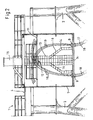
- offshore platform construction 1 comprises a plurality of foundation piles 2, which are rammed into the seabed and one of these excluded transition piece 3, which defines a working platform 4.
- annular flange 5 is provided with fastening bolts not shown for securing a steel tube of a mast of a wind turbine as a structure on the transition piece.
- the work platform 4 is secured in a known manner with a railing 6.
- a walk-in installation tank 7 or installation basement is provided below the work platform 4, for example, have a diameter of about 5 m, a clear height of about 5 m and a circular cross-section can.
- the installation tank 7 is part of the transition piece 3 and forms according to the described embodiment, a lower-side extension of the be connected to the annular flange 5 structure, such as a concrete pipe.
- the installation tank 7 is closed off with a walk-on grate 8; on the bottom side, the installation tank comprises a bottom 10 which is closed except for a plurality of cable entries 9.
- a working platform is referred to, which extends approximately in the upper third of the installation tank 7 below the grate 8 and parallel thereto.
- the working platform 11 extends circumferentially peripherally and is provided with a central passage 12 for a ladder structure 13.
- the ladder structure 13 may be formed, for example, as a polygonal conductor structure or ladder tunnel extending from the floor 10 to the grate 8 over the entire clear height of the installation tank 7.
- This conductor structure comprises mounting brackets 14 for cable fixation.
- the ladder structure 13 further comprises a plurality of cable bridges 16 (the number of cable bridges 16 is not critical to the invention), which are also designed as ladder constructions with mounting brackets 14 and the bridge like from the bottom 10 of the installation tank 7 off-center in the region of the cable entries 9 in the middle the conductor tree structure 13 extend.
- the ladder structure 13 forms a continuous from bottom to top through the installation tank 7 cable channel, which is guided in the centrally arranged control cabinet 15.
- the installation tank 7 further comprises ladders / steps for embarking on the work platform 11 from the working platform 4 as well as for the inspection of the floor 10 of the installation tank 7. These stairs are not shown for reasons of simplification.
- Fig. 1 shows two passed through the installation tank 7 submarine cable 17 in unassembled and uncoated state.
- the submarine cables are guided through the J-tubes 18 connected to the bottom 10 of the installation tank 7 via the cable entries 9 into the installation tank 7.
- the J-tubes 18 are sealed from the outside connected.
- the submarine cables 17 are pulled straight up from the working platform 4 by means of special devices (pull-down stands) through the J-tubes 18. If these are pulled out of the J-tubes 18 over the predetermined length, they are fixed in the cable inlets 9, which are designed as a clamping seat for the submarine cables 17.
- the cable entries 9 may for example have clamping seats in the form of clamping cups and / or clamping wedges.
- spindle-actuable clamping jaws can be arranged adjustable within the cable entries 9.
- the submarine cables 17 are freed from their outer sheath, if necessary from their reinforcement and a braided shield.
- the reinforcement and the braided shield are used partly for fixing in the region of the cable entry 9.
- Fig. 2 shows the stripped state of the submarine cable 17, these each comprise three live insulated wires 19.
- the individual wires 19 are then (see Fig. 3 ) via the cable bridges 16 via the approximately centrally upwardly extending framework of the conductor structure 13 through the bushing 12 into the control cabinet 15.
- the individual wires 19 are fixed to the mounting brackets 14.
- the installation tank 7 and the arrangement of the working platform 11 are sized and selected so that the individual wires 19 can be installed and fixed in compliance with the allowable bending radius within the installation tank 7.
Landscapes
- Engineering & Computer Science (AREA)
- General Engineering & Computer Science (AREA)
- Mechanical Engineering (AREA)
- Civil Engineering (AREA)
- Structural Engineering (AREA)
- Laying Of Electric Cables Or Lines Outside (AREA)
Abstract
Die Erfindung betrifft eine Offshore-Plattform-Konstruktion (1) für eine Windkraftanlage mit wenigstens einer Gründungsstruktur und mit wenigstens einem von der Gründungsstruktur aufgenommenen Übergangsstück (3), welches eine Arbeitsplattform (4) bildet und eine Anschlussstruktur über eine auf der Plattform zu errichtende Windkraftanlage aufweist. Die Offshore-Plattform-Konstruktion (1) zeichnet sich dadurch aus, dass das Übergangsstück (3) einen begehbaren Installationstank (7) umfasst, der sich in Einbaulage unterhalb der Arbeitsplattform (4) erstreckt und in welchem Mittel zum Durchführen und Abhängen von Seekabeln (17) vorgesehen ist.
Description
- Die Erfindung betrifft eine Offshore-Plattform-Konstruktion, insbesondere für eine Windkraftanlage mit wenigstens einer Gründungsstruktur, mit wenigstens einem von der Gründungstruktur aufgenommenen Übergangsstück, welches eine Plattform definiert und welches eine Anschlussstruktur für ein auf der Plattform zu errichtendes Bauwerk aufweist. Ein Bauwerk in diesem Sinne wäre beispielsweise einer Stahl- oder Betonkonstruktion in Form eines Betonmastes mit vorgespannter Bewehrung, dessen von der Gründung abliegendes Ende in bekannter Art und Weise einen Windkraftgenerator aufnimmt.
- Offshore-Plattformen der vorbezeichneten Art sind beispielsweise mit Gründungen als sogenannte Monopiles, Tripiles etc. ausgeführt. Die Gründung ist meistens mit einem oder mehreren Gründungspfählen in den Meeresgrund gerammt. Die Gründungspfähle tragen ein Übergangsstück welches eine Plattform, beispielsweise eine Arbeitsplattform definiert und mit einem Ringflansch als Anschlussstruktur für den Betonmast versehen ist.
- Offshore-Windgeneratoren sind häufig in Feldern angeordnet, die Windgeneratoren sind miteinander verschaltet und können beispielsweise zunächst feldweise an eine Offshore-Umspannanlage angeschlossen sein. Von der Umspannanlage werden dann entsprechend ausgebildete Seekabel auf dem Meeresgrund an Land geführt.
- Die einzelnen Windkraftgeneratoren sind jeweils an dreiadrige Leitungen angeschlossen, die verhältnismäßig schwer und steif sind. Die Leitungen bzw. Kabel sind vom Meeresgrund durch die Bauwerksanschlussstruktur und den Turm/Mast zum Windgenerator zu führen, wobei diese innerhalb des Bauwerks abgehängt werden. Die einzelnen Adern der Leitungen sind in einem gemeinsamen Kabelmantel angeordnet, der diese auf dem Meeresgrund hinreichend gegen äußere Einwirkungen schützt. Darüber hinaus sind die Kabel mit wenigstens einer Geflechtsabschirmung umhüllt und mit einer Armierung. Einzelne Adern haben Querschnitte von bis zu 800 mm2 und mehr, so dass sowohl der praktisch mögliche als auch der zulässige Biegeradius der Kabel verhältnismäßig groß ist. Dieser Biegeradius kann bis zu 1,5 m und mehr betragen. Die Kabelführung, Aufhängung und Zugentlastung innerhalb des Bauwerks ist damit verhältnismäßig aufwändig zu bewerkstelligen.
- Der Erfindung liegt daher das Problem zugrunde, eine Offshore-Plattform-Konstruktion im Hinblick auf die Durchführung von Seekabeln zu verbessern. Insbesondere soll die Montage der Seekabel besonders einfach sein.
- Die Aufgabe wird gelöst durch eine Offshore-Plattform-Konstruktion, insbesondere für eine Windkraftanlage, mit wenigstens einer Gründungsstruktur, mit wenigstens einem von der Gründungsstruktur aufgenommenen Übergangsstück, welches eine Plattform definiert und vorzugsweise eine Anschlussstruktur für ein auf der Plattform zu errichtendes Bauwerk aufweist, wobei sich die Offshore- Plattform-Konstruktion insbesondere dadurch auszeichnet, dass das Übergangsstück wenigstens einen, vorzugsweise begehbaren Installationstank umfasst, der sich in Einbaulage unterhalb der Plattform erstreckt und in welchem Mittel zum Durchführen und Abhängen von Seekabeln vorgesehen sind.
- Selbstverständlich kann das Übergangsstück auch ein freiliegendes Deck ohne eine Anschlussstruktur für ein Bauwerk umfassen. Die erfindungsgemäße Lösung ist ohne weiteres auch auf Offshore Öl und Gas Förder- und Explorationsplattformen übertragbar.
- Erfindungsgemäß ist ein separater Installationstank/Installationskeller vorgesehen, der sich unterhalb der Plattform erstreckt und der begehbar ist. Innerhalb des Installationstanks können die Seekabel zugfest abgehängt werden und für eine Durchführung zu einem auf der Plattform errichteten Bauwerk gegebenenfalls vereinzelt werden.
- Bei einer bevorzugten Variante der Offshore-Plattform-Konstruktion gemäß der Erfindung ist vorgesehen, dass der Installationstank bodenseitig wenigstens eine außermittig vorgesehene Kabeleinführung aufweist.
- Die Anordnung einer solchen bodenseitigen Kabeleinführung außermittig, bei einem vorzugsweise mit rundem Querschnitt versehenen Installationstank, trägt dem Umstand Rechnung, dass die Seekabel nur mit einem verhältnismäßig großen Biegeradius vom Meeresgrund aufwärts geführt werden können.
- Ein Installationstank gemäß der Erfindung hat vorzugsweise eine lichte Weite von etwa 5 m und eine lichte Höhe von 5 m. Dieser kann bodenseitig etwa 21 m über der Wasserlinie angeordnet sein.
- Zweckmäßigerweise ist die Kabeleinführung an wenigstens ein sich unterhalb des Installationstanks erstreckendes J-Rohr angeschlossen, welches eine J-förmige Führung des oder der Seekabel innerhalb des zulässigen Biegeradius ermöglicht.
- Besonders zweckmäßig ist es, wenn zur Abhängung von Seekabeln wenigstens ein Kabelklemmsitz in wenigstens einer Kabeleinführung vorgesehen ist. So besteht die Möglichkeit, die Seekabel innerhalb des Installationstanks von ihrer äußeren Ummantelung zu befreien und/oder zu vereinzeln.
- Zweckmäßigerweise umfasst der Installationstank wenigstens eine begehbare Arbeitsbühne.
- Bei einer besonders bevorzugten Ausführungsform der Offshore-Plattform-Konstruktion gemäß der Erfindung ist vorgesehen, dass innerhalb des Installationstanks wenigstens eine Kabelführung, vorzugsweise in Form einer Leiterbaum-Konstruktion zur Fixierung von vereinzelten isolierten Stromkabeln vorgesehen ist, die sich vorzugsweise über die gesamte lichte Höhe des Installationstanks erstreckt. Eine solche Leiterbaum-Konstruktion kann beispielsweise als Gerüst mit einer Vielzahl von Montagetraversen ausgebildet sein.
- Die Kabelführung kann wenigstens eine Kabelbrücke umfassen, die sich bodenseitig von einer Kabeleinführung aus zu einer etwa mittigen Kabelführung erstreckt.
- Die Offshore-Plattform-Konstruktion gemäß der Erfindung umfasst vorzugsweise wenigstens eine Schaltanlage, die zweckmäßigerweise oberhalb des Installationstanks auf der Plattform oder innerhalb eines Montageflansches für die Bauwerkskonstruktion angeordnet ist.
- Die Erfindung wird nachstehend anhand eines in den Zeichnungen dargestellten Ausführungsbeispiels erläutert.
- Es zeigen:
- Fig. 1
- eine schematische Schnittansicht einer Offshore-Plattform-Konstruktion gemäß der Erfindung mit in den Installationstank eingezogenen Seekabeln,
- Fig. 2
- eine der
Fig. 1 entsprechende Ansicht, die die Verlegung der vereinzelten Adern der Seekabel veranschaulicht und - Fig. 3
- eine den
Fig. 1 und2 entsprechende Ansicht mit fertig verlegten und installierten Kabeln. - Die in
Fig. 1 dargestellte Offshore-Plattform-Konstruktion 1 umfasst mehrere Gründungspfähle 2, die in den Meeresboden gerammt sind sowie ein von diesen ausgenommenes Übergangsstück 3, welches eine Arbeitsplattform 4 definiert. In etwa der Ebene der Arbeitsplattform 4 ist auf dem Übergangsstück ein Ringflansch 5 mit nicht näher dargestellten Befestigungsbolzen zur Sicherung einer Stahlröhre eines Mastes einer Windkraftanlage als Bauwerk vorgesehen. - Die Arbeitsplattform 4 ist in bekannter Art und Weise mit einem Geländer 6 gesichert.
- Unterhalb der Arbeitsplattform 4 ist ein begehbarer Installationstank 7 bzw. Installationskeller vorgesehen, der beispielsweise einen Durchmesser von etwa 5 m, eine lichte Höhe von etwa 5 m sowie einen kreisrunden Querschnitt aufweisen kann. Der Installationstank 7 ist Bestandteil des Übergangsstücks 3 und bildet gemäß dem beschriebenen Ausführungsbeispiel eine unterseitige Verlängerung des an den Ringflansch 5 anzuschließenden Bauwerks, beispielsweise einer Betonröhre.
- Oberseitig ist der Installationstank 7 mit einem begehbaren Rost 8 abgeschlossen, bodenseitig umfasst der Installationstank einen bis auf mehrere Kabeleinführungen 9 geschlossenen Boden 10.
- Mit 11 ist eine Arbeitsbühne bezeichnet, die sich etwa im oberen Drittel des Installationstanks 7 unterhalb des Rostes 8 und parallel dazu erstreckt. Die Arbeitsbühne 11 erstreckt sich randseitig umlaufend und ist mit einer mittigen Durchführung 12 für eine Leiterbaumstruktur 13 versehen. Die Leiterbaumstruktur 13 kann beispielsweise als polygonale Leiterstruktur oder Leitertunnel ausgebildet sein, die sich vom Boden 10 bis zu dem Rost 8 über die gesamte lichte Höhe des Installationstanks 7 erstreckt. Diese Leiterstruktur umfasst Montagetraversen 14 zur Kabelfixierung.
- Mit 15 ist ein Schaltschrank bezeichnet, der mittig oberhalb der Durchführung 12 angeordnet ist.
- Die Leiterbaumstruktur 13 umfasst weiterhin mehrere Kabelbrücken 16 (die Anzahl der Kabelbrücken 16 ist für die Erfindung nicht kritisch), die ebenfalls als Leiterkonstruktionen mit Montagetraversen 14 ausgeführt sind und die sich brückenartig vom Boden 10 des Installationstanks 7 außermittig im Bereich der Kabeleinführungen 9 in die Mitte der Leiterbaumstruktur 13 erstrecken. Die Leiterbaumstruktur 13 bildet einen von unten nach oben durch den Installationstank 7 durchgehenden Kabelkanal, der in den mittig angeordneten Schaltschrank 15 geführt ist.
- Der Installationstank 7 umfasst weiterhin Leitern/Stiege zur Begehung der Arbeitsbühne 11 von der Arbeitsplattform 4 aus sowohl als auch zur Begehung des Bodens 10 des Installationstanks 7. Diese Stiege sind aus Vereinfachungsgründen nicht dargestellt.
- Nachstehend wird der Vorgang der Kabeleinführung und Durchführung in den Installationstank 7 gemäß der Erfindung erläutert.
-
Fig. 1 zeigt zwei durch den Installationstank 7 hindurchgeführte Seekabel 17 in nicht-montiertem und nicht-entmanteltem Zustand. Die Seekabel sind durch an den Boden 10 des Installationstanks 7 angeschlossene J-Rohre 18 über die Kabeleinführungen 9 in den Installationstank 7 geführt. An die Kabeleinführungen 9 sind die J-Rohre 18 von außen abgedichtet angeschlossen. - Die Seekabel 17 werden von der Arbeitsplattform 4 aus mittels spezieller Vorrichtungen (Zugstativen) durch die J-Rohre 18 gerade hoch gezogen. Sind diese über die vorgegebene Länge aus den J-Rohren 18 herausgezogen, werden sie in den Kabeleinführungen 9, die als Klemmsitz für die Seekabel 17 ausgebildet sind, festgelegt. Die Kabeleinführungen 9 können beispielsweise Klemmsitze in Form von Klemmtöpfen und/oder Klemmkeilen aufweisen. Darüber hinaus können auch spindelbetätigbare Klemmbacken innerhalb der Kabeleinführungen 9 verstellbar angeordnet sein.
- In dem abgehängten Zustand werden die Seekabel 17 von ihrer äußeren Ummantelung, gegebenenfalls von ihrer Armierung und einer Geflechtsabschirmung befreit. Die Armierung und die Geflechtsabschirmung werden zum Teil zur Fixierung im Bereich der Kabeleinführung 9 verwendet.
-
Fig. 2 zeigt den entmantelten Zustand der Seekabel 17, diese umfassen jeweils drei stromführende isolierte Adern 19. Die einzelnen Adern 19 werden sodann (sieheFig. 3 ) über die Kabelbrücken 16 über das sich etwa mittig aufwärts erstreckende Gerüst der Leiterbaumstruktur 13 durch die Durchführung 12 in den Schaltschrank 15 verlegt. Dabei werden die einzelnen Adern 19 an den Montagetraversen 14 fixiert. - Wie dies insbesondere der
Fig. 2 zu entnehmen ist, sind der Installationstank 7 und die Anordnung der Arbeitsbühne 11 so bemessen und gewählt, dass die einzelnen Adern 19 unter Einhaltung des zulässigen Biegeradius innerhalb des Installationstanks 7 verlegt und fixiert werden können. -
- 1
- Offshore-Plattform-Konstruktion
- 2
- Gründungspfähle
- 3
- Übergangsstück
- 4
- Arbeitsplattform
- 5
- Ringflansch
- 6
- Geländer
- 7
- Installationstank
- 8
- Rost
- 9
- Kabeleinführungen
- 10
- Boden des Installationstanks
- 11
- Arbeitsbühne des Installationstanks
- 12
- Durchführung
- 13
- Leiterbaumstruktur
- 14
- Montagetraversen
- 15
- Schaltschrank
- 16
- Kabelbrücken
- 17
- Seekabel
- 18
- J-Rohre
- 19
- Adern
Claims (11)
- Offshore-Plattform-Konstruktion (1), insbesondere für eine Windkraftanlage, mit wenigstens einer Gründungsstruktur, mit wenigstens einem von der Gründungsstruktur aufgenommenen Übergangsstück (3), welches eine Plattform definiert und vorzugsweise eine Anschlussstruktur für ein auf der Plattform zu errichtendes Bauwerk aufweist, dadurch gekennzeichnet, dass das Übergangsstück (3) einen wenigstens vorzugsweise begehbaren Installationstank (7) umfasst, der sich in Einbaulage unterhalb der Plattform erstreckt und in welchem Mittel zum Durchführen und Abhängen von Seekabeln (17) vorgesehen sind.
- Offshore-Plattform-Konstruktion nach Anspruch 1, dadurch gekennzeichnet, dass der Installationstank (7) bodenseitig wenigstens eine Kabeleinführung (9) aufweist.
- Offshore-Plattform-Konstruktion nach Anspruch 2, dadurch gekennzeichnet, dass wenigstens eine Kabeleinführung außermittig des Installationstanks (7) vorgesehen ist.
- Offshore-Plattform-Konstruktion nach Anspruch 2 oder 3, dadurch gekennzeichnet, dass die Kabeleinführung (9) wenigstens an ein sich unterhalb des Installationstanks (7) erstreckendes vorzugsweise als J-Rohr (18) ausgebildetes Rohr angeschlossen ist.
- Offshore-Plattform-Konstruktion nach einem der Ansprüche 1-4, dadurch gekennzeichnet, dass als Mittel zur Abhängung von Seekabeln (17) wenigstens ein Kabelklemmsitz in wenigstens einer Kabeleinführung (9) vorgesehen ist.
- Offshore-Plattform-Konstruktion nach einem der Ansprüche 1-5, dadurch gekennzeichnet, dass der Installationstank (7) wenigstens eine vorzugsweise begehbare Arbeitsbühne (11) umfasst.
- Offshore-Plattform-Konstruktion nach einem der Ansprüche 1-6, dadurch gekennzeichnet, dass innerhalb des Installationstanks (7) wenigstens eine Kabelführung, vorzugsweise in Form einer Leiterbaum-Konstruktion (13) zur Fixierung von vereinzelten isolierten Stromkabeln vorgesehen ist, die sich vorzugsweise über die gesamte lichte Höhe des Installationstanks (7) erstreckt.
- Offshore-Plattform-Konstruktion nach Anspruch 7, dadurch gekennzeichnet, dass die Leiterbaum-Konstruktion (16) als Gerüst mit einer Vielzahl von Montagetraversen (14) ausgebildet ist.
- Offshore-Plattform-Konstruktion nach einem der Ansprüche 7 oder 8, dadurch gekennzeichnet, dass die Leiterbaum-Konstruktion (13) wenigstens einen sich über wesentliche Teile der Höhe des Installationstanks (7) erstreckenden Kabeltunnel als Kabelführung bildet.
- Offshore-Plattform-Konstruktion nach einem der Ansprüche 7 oder 9, dadurch gekennzeichnet, dass die Leiterbaum-Konstruktion (13) wenigstens eine Kabelbrücke (16) umfasst, die sich bodenseitig von einer Kabeleinführung (9) zu einer etwa mittigen Kabelführung erstreckt.
- Offshore-Plattform-Konstruktion nach einem der Ansprüche 1-10, gekennzeichnet durch wenigstens eine Schaltanlage, die oberhalb des Installationstanks (7) angeordnet ist.
Applications Claiming Priority (1)
| Application Number | Priority Date | Filing Date | Title |
|---|---|---|---|
| DE102011117162A DE102011117162A1 (de) | 2011-10-28 | 2011-10-28 | Offshore-Plattform-Konstruktion |
Publications (1)
| Publication Number | Publication Date |
|---|---|
| EP2586917A2 true EP2586917A2 (de) | 2013-05-01 |
Family
ID=46798963
Family Applications (1)
| Application Number | Title | Priority Date | Filing Date |
|---|---|---|---|
| EP12006036.3A Withdrawn EP2586917A2 (de) | 2011-10-28 | 2012-08-24 | Offshore-Plattform-Konstruktion |
Country Status (2)
| Country | Link |
|---|---|
| EP (1) | EP2586917A2 (de) |
| DE (1) | DE102011117162A1 (de) |
Cited By (4)
| Publication number | Priority date | Publication date | Assignee | Title |
|---|---|---|---|---|
| CN103334415A (zh) * | 2013-07-01 | 2013-10-02 | 南通天田机床有限公司 | 一种新型钻井平台挡风墙 |
| CN103821122A (zh) * | 2014-03-04 | 2014-05-28 | 中国水电顾问集团华东勘测设计研究院有限公司 | 海上平台的跨缝结构及其安装方法 |
| WO2018162104A1 (en) * | 2017-03-09 | 2018-09-13 | Siemens Wind Power A/S | Cable hang-off arrangement |
| CN112086893A (zh) * | 2020-08-25 | 2020-12-15 | 中国能源建设集团广东省电力设计研究院有限公司 | 一种海上升压站的登船结构 |
Family Cites Families (1)
| Publication number | Priority date | Publication date | Assignee | Title |
|---|---|---|---|---|
| DE102008028476A1 (de) * | 2008-06-14 | 2009-12-17 | Joachim Falkenhagen | Offshore-Umspannwerk mit Kabelbogen |
-
2011
- 2011-10-28 DE DE102011117162A patent/DE102011117162A1/de not_active Withdrawn
-
2012
- 2012-08-24 EP EP12006036.3A patent/EP2586917A2/de not_active Withdrawn
Non-Patent Citations (1)
| Title |
|---|
| None |
Cited By (8)
| Publication number | Priority date | Publication date | Assignee | Title |
|---|---|---|---|---|
| CN103334415A (zh) * | 2013-07-01 | 2013-10-02 | 南通天田机床有限公司 | 一种新型钻井平台挡风墙 |
| CN103821122A (zh) * | 2014-03-04 | 2014-05-28 | 中国水电顾问集团华东勘测设计研究院有限公司 | 海上平台的跨缝结构及其安装方法 |
| CN103821122B (zh) * | 2014-03-04 | 2016-01-27 | 中国水电顾问集团华东勘测设计研究院有限公司 | 海上平台的跨缝结构及其安装方法 |
| WO2018162104A1 (en) * | 2017-03-09 | 2018-09-13 | Siemens Wind Power A/S | Cable hang-off arrangement |
| CN110582910A (zh) * | 2017-03-09 | 2019-12-17 | 西门子歌美飒可再生能源公司 | 线缆悬挂装置 |
| US11008722B2 (en) | 2017-03-09 | 2021-05-18 | Siemens Gamesa Renewable Energy A/S | Cable hang-off arrangement |
| CN112086893A (zh) * | 2020-08-25 | 2020-12-15 | 中国能源建设集团广东省电力设计研究院有限公司 | 一种海上升压站的登船结构 |
| CN112086893B (zh) * | 2020-08-25 | 2023-02-03 | 中国能源建设集团广东省电力设计研究院有限公司 | 一种海上升压站的登船结构 |
Also Published As
| Publication number | Publication date |
|---|---|
| DE102011117162A1 (de) | 2013-05-02 |
Similar Documents
| Publication | Publication Date | Title |
|---|---|---|
| EP2909476B1 (de) | Versorgungsgerüst für einen turm, turm mit einem versorgungsgerüst sowie verfahren zum errichten eines versorgungsgerüsts im inneren eines turms | |
| EP1145397B1 (de) | Verfahren zum verlegen von elektrischen kabeln von einer ersten offshore-windenergieanlage zu einer zweiten offshore-windenergieanlage | |
| DE102012003572A1 (de) | Offshore-Plattform-Konstruktion sowie Verfahren zur Errichtung einer Offshore-Windturbinenstation | |
| DE3138819C2 (de) | Verfahren zur Montage eines zwischen seinen Verankerungsstellen frei gespannt verlaufenden Zuggliedes, insbesondere eines Schrägkabels für eine Schrägkabelbrücke | |
| DE102008028476A1 (de) | Offshore-Umspannwerk mit Kabelbogen | |
| DE102016219413A1 (de) | Elektrische Baueinheit für eine Windenergieanlage | |
| EP3064648B1 (de) | Bootsanleger für eine offshore-anlage, offshore-anlage mit einem solchen bootsanleger und verfahren zum montieren des bootsanlegers | |
| EP4491835A2 (de) | Turm mit konischen stahladapterelementen | |
| EP3530809B1 (de) | Verbindungsstruktur für eine meeresinstallation | |
| DE102017009682A1 (de) | Plattformanordnung, Offshore-Bauwerk, Verfahren zum Installieren einer Plattformanordnung | |
| EP2239398B1 (de) | Turm | |
| EP3635179B1 (de) | Offshore anlage | |
| DE102011117162A1 (de) | Offshore-Plattform-Konstruktion | |
| EP1336559B1 (de) | Verfahren zum Absenken eines Schwimmkörpers eines Schwimmfundaments | |
| EP0607915B1 (de) | Verfahren und Vorrichtung zum Verlängern eines im Betrieb befindlichen Freileitungsmastes | |
| WO2020057864A1 (de) | Windenergieanlagen-turmsegment für einen windenergieanlagen-turm und verfahren | |
| DE60027228T2 (de) | Verfahren zum Installieren einer Leitung oder dergleichen an einem Berghang unter Verwendung eines Kabels | |
| EP3530810B1 (de) | Offshore-plattform mit wenigstens einem rammpfahl | |
| WO2020114789A1 (de) | Verfahren zum vorspannen eines turms einer windenergieanlage | |
| AT506952B1 (de) | Instandhaltungssystem | |
| DE19803954A1 (de) | Verfahren und Vorrichtung zum Erhöhen von Masten | |
| DE102018207742B4 (de) | Vorrichtung und Verfahren zum Installieren wenigstens zweier Spannelemente an einem Bauwerk oder Teilbauwerk | |
| EP2351885A1 (de) | Offshore-Bauwerk | |
| DE2323135A1 (de) | Verfahren zum errichten eines turmes od. dgl. auf dem meeresboden | |
| DE102008050488A1 (de) | Verfahren zur Verlegung eines elektrischen Leiters und Verlegevorrichtung |
Legal Events
| Date | Code | Title | Description |
|---|---|---|---|
| PUAI | Public reference made under article 153(3) epc to a published international application that has entered the european phase |
Free format text: ORIGINAL CODE: 0009012 |
|
| AK | Designated contracting states |
Kind code of ref document: A2 Designated state(s): AL AT BE BG CH CY CZ DE DK EE ES FI FR GB GR HR HU IE IS IT LI LT LU LV MC MK MT NL NO PL PT RO RS SE SI SK SM TR |
|
| AX | Request for extension of the european patent |
Extension state: BA ME |
|
| STAA | Information on the status of an ep patent application or granted ep patent |
Free format text: STATUS: THE APPLICATION IS DEEMED TO BE WITHDRAWN |
|
| 18D | Application deemed to be withdrawn |
Effective date: 20150303 |