EP2586980A2 - Turbinenschaufelschienendämpfer - Google Patents
Turbinenschaufelschienendämpfer Download PDFInfo
- Publication number
- EP2586980A2 EP2586980A2 EP12182434.6A EP12182434A EP2586980A2 EP 2586980 A2 EP2586980 A2 EP 2586980A2 EP 12182434 A EP12182434 A EP 12182434A EP 2586980 A2 EP2586980 A2 EP 2586980A2
- Authority
- EP
- European Patent Office
- Prior art keywords
- rail
- shroud
- blade
- damper
- slot
- Prior art date
- Legal status (The legal status is an assumption and is not a legal conclusion. Google has not performed a legal analysis and makes no representation as to the accuracy of the status listed.)
- Granted
Links
Images




Classifications
-
- F—MECHANICAL ENGINEERING; LIGHTING; HEATING; WEAPONS; BLASTING
- F01—MACHINES OR ENGINES IN GENERAL; ENGINE PLANTS IN GENERAL; STEAM ENGINES
- F01D—NON-POSITIVE DISPLACEMENT MACHINES OR ENGINES, e.g. STEAM TURBINES
- F01D5/00—Blades; Blade-carrying members; Heating, heat-insulating, cooling or antivibration means on the blades or the members
- F01D5/12—Blades
- F01D5/22—Blade-to-blade connections, e.g. for damping vibrations
- F01D5/225—Blade-to-blade connections, e.g. for damping vibrations by shrouding
-
- F—MECHANICAL ENGINEERING; LIGHTING; HEATING; WEAPONS; BLASTING
- F01—MACHINES OR ENGINES IN GENERAL; ENGINE PLANTS IN GENERAL; STEAM ENGINES
- F01D—NON-POSITIVE DISPLACEMENT MACHINES OR ENGINES, e.g. STEAM TURBINES
- F01D25/00—Component parts, details, or accessories, not provided for in, or of interest apart from, other groups
- F01D25/04—Antivibration arrangements
- F01D25/06—Antivibration arrangements for preventing blade vibration
-
- F—MECHANICAL ENGINEERING; LIGHTING; HEATING; WEAPONS; BLASTING
- F01—MACHINES OR ENGINES IN GENERAL; ENGINE PLANTS IN GENERAL; STEAM ENGINES
- F01D—NON-POSITIVE DISPLACEMENT MACHINES OR ENGINES, e.g. STEAM TURBINES
- F01D5/00—Blades; Blade-carrying members; Heating, heat-insulating, cooling or antivibration means on the blades or the members
- F01D5/02—Blade-carrying members, e.g. rotors
- F01D5/10—Anti- vibration means
-
- F—MECHANICAL ENGINEERING; LIGHTING; HEATING; WEAPONS; BLASTING
- F01—MACHINES OR ENGINES IN GENERAL; ENGINE PLANTS IN GENERAL; STEAM ENGINES
- F01D—NON-POSITIVE DISPLACEMENT MACHINES OR ENGINES, e.g. STEAM TURBINES
- F01D5/00—Blades; Blade-carrying members; Heating, heat-insulating, cooling or antivibration means on the blades or the members
- F01D5/12—Blades
- F01D5/14—Form or construction
- F01D5/16—Form or construction for counteracting blade vibration
-
- F—MECHANICAL ENGINEERING; LIGHTING; HEATING; WEAPONS; BLASTING
- F05—INDEXING SCHEMES RELATING TO ENGINES OR PUMPS IN VARIOUS SUBCLASSES OF CLASSES F01-F04
- F05D—INDEXING SCHEME FOR ASPECTS RELATING TO NON-POSITIVE-DISPLACEMENT MACHINES OR ENGINES, GAS-TURBINES OR JET-PROPULSION PLANTS
- F05D2260/00—Function
- F05D2260/96—Preventing, counteracting or reducing vibration or noise
-
- Y—GENERAL TAGGING OF NEW TECHNOLOGICAL DEVELOPMENTS; GENERAL TAGGING OF CROSS-SECTIONAL TECHNOLOGIES SPANNING OVER SEVERAL SECTIONS OF THE IPC; TECHNICAL SUBJECTS COVERED BY FORMER USPC CROSS-REFERENCE ART COLLECTIONS [XRACs] AND DIGESTS
- Y10—TECHNICAL SUBJECTS COVERED BY FORMER USPC
- Y10S—TECHNICAL SUBJECTS COVERED BY FORMER USPC CROSS-REFERENCE ART COLLECTIONS [XRACs] AND DIGESTS
- Y10S416/00—Fluid reaction surfaces, i.e. impellers
- Y10S416/50—Vibration damping features
Definitions
- This invention relates to rotor blades and specifically to the mechanical damping of vibratory energy in the blades of rotor assemblies during operation.
- Rotor assemblies are used in a variety of turbo-machines, such as turbines and compressors.
- turbo-machines such as turbines and compressors.
- fluid forces induce vibratory stresses on the blades, resulting in high cycle fatigue and potential failure of the blades.
- Dampers commonly frictional dampers, are utilized to reduce the magnitude of these dynamic stresses, thereby increasing operational life of the blades.
- Frictional damping is effective so long as relative motion exists between the damper and the blade.
- typical flat plate shroud dampers become too heavy and the frictional damper sticks to the shroud due to friction, thereby reducing its effectiveness.
- Typical lighter weight damper designs consist of loss fitting rivets. These rivets are hard to form due to the many tight tolerance features required and they are exposed to the main gas flow.
- Conventional shrouds typically include one or more sealing rails that extend radially outward from the shroud in close proximity to the stationary housing and typically extend continuously across the top surface of the shroud between first and second circumferential sides.
- Typical previous shroud frictional dampers are retained by extra features added to the shroud. These added features are located on the shroud at the furthest distance from blade which increases the shroud overhung weight. These added features increase the centrifugal induced bending stress in the shroud which may result in potential failure of the rotor assembly due to high cycle fatigue. To counteract this, the shroud thickness must be increased. This increase in shroud thickness also results in higher centrifugal stress in the blade at the blade's two critical locations, the blade shank and firtree.
- a device for damping of vibratory energy in turbine blades of rotor assemblies during operation comprising: a first turbine blade having a shroud with a sealing rail, the sealing rail having a generally circumferential slot at each end of the rail; a second turbine blade adjacent the first blade and having a shroud with a sealing rail, the sealing rail having a generally circumferential slot at each end of the rail such that a slot at the end of the first blade rail nearest the second blade is adjacent and opposing a slot at the end of the second blade rail nearest the first blade; and a damper element positioned in and extending between the adjacent slots of the first blade rail and the second blade rail.
- a rotor for use with a turbine having a plurality of blades extending radially outward comprising: a plurality of shrouds, each shroud being positioned radially outward of and attached to one of the blades a plurality of sealing rails, each sealing rail of a radially outward side of each shroud, the sealing rail having a generally circumferential slot at each end of the rail; and a plurality of damper elements, each damper element being positioned in and extending between adjacent slots of opposing ends of adjacent blade rails.
- a rotor for use with a turbine, the rotor comprising: a plurality of blades extending radially outward, each blade having a shroud positioned at a radially outward end of the blade and containing a sealing rail, each sealing rail having a generally circumferential slot at each end of the rail; and a plurality of damper elements made from metal or ceramic, each damper element being positioned in the adjacent opposing slots of adjacent sealing rails, each damper element being generally "U” shaped with the bottom of the "U” engaging the back of the slots and the sides of the "U” extend along sides of the sealing rail.
- Embodiments of the present invention relate to a damper arrangement on the sealing rail of turbo-machine shrouds where the damper in the rail is outside of the main gas flow. At least the preferred embodiments of this invention use the existing rail and require no modification to the shroud to retain the damper.
- the rail damper may comprise a shim stock having its ends oriented to function with specific shroud rail configurations. At least the preferred embodiments of the present invention do not require any special retainment features would add weight to the shroud and result in higher shroud and blade safety factors.
- FIG. 1 is a perspective view illustrating one embodiment of the present invention in a rotor assembly used in turbo-machines, showing turbine blades having shrouds with rails and damper elements.
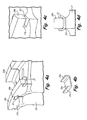
- FIG.2a is a perspective view of the embodiment in a shroud rail.
- FIG. 2b is an enlarged perspective view of the damper used in FIG. 1 .
- FIG. 2c is an enlarged perspective view of the slot in the shroud and rail in FIG. 2a .
- FIG. 2d is an end view of the damper in the slot of FIG. 2c .
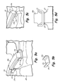
- FIG. 3 a perspective view of another embodiment of this invention in a shroud rail.
- FIG. 3b is an enlarged perspective view of the damper used in FIG 3a .
- FIG. 3c is an enlarged perspective view of the slot in the shroud and rail in FIG. 3a .
- FIG. 3d is an end view of the damper in the slot of FIG. 3c .
- FIG. 4 a perspective view of another embodiment of this invention in a shroud rail.
- FIG. 4b is an enlarged perspective view of the damper used in FIG 4a .
- FIG. 4c is an enlarged perspective view of the slot in the shroud and rail in FIG. 4a .
- FIG. 4d is an end view of the damper in the slot of FIG. 4c .
- FIG. 5 a perspective view of another embodiment of this invention in a shroud rail.
- FIG. 5b is an enlarged perspective view of the damper used in FIG 5a .
- FIG. 5c is an enlarged perspective view of the slot in the shroud and rail in FIG. 5a .
- FIG. 5d is an end view of the damper in the slot of FIG. 5c .
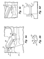
- FIG. 6 a perspective view of another embodiment of this invention in a shroud rail.
- FIG. 6b is an enlarged perspective view of the damper used in FIG 6a .
- FIG. 6c is an enlarged perspective view of the slot in the shroud and rail in FIG. 6a .
- FIG. 6d is an end view of the damper in the slot of FIG. 6c .
- FIG. 7 a perspective view of another embodiment of this invention in a shroud rail.
- FIG. 7b is an enlarged perspective view of the damper used in FIG 7a .
- FIG. 7c is an enlarged perspective view of the slot in the shroud and rail in FIG. 7a .
- FIG. 7d is an end view of the damper in the slot of FIG. 7c .
- FIG. 8 a perspective view of another embodiment of this invention in a shroud rail.
- FIG. 8b is an enlarged perspective view of the damper used in FIG 8a .
- FIG. 8c is an enlarged perspective view of the slot in the shroud and rail in FIG. 8a .
- FIG. 8d is an end view of the damper in the slot of FIG. 68c.
- FIG. 1 shows a perspective view of an assembly, 10 generally, of a pair of turbine blades 11a and 11b of a turbo-machine such as a gas turbine engine.
- Blades 11a and 11b include firtrees 11a and 11b, blade shanks 12a and 12b, platforms 13a and 13b, airfoils 15a and 15b, shrouds 17a and 17b, upstream rails 19a and 19b, and downstream rails 20a and 20b, respectively.
- Airfoils 15a and 15b extend radially out from platforms 13a and 13b to shrouds 17a and 17b.
- Shrouds 17a and 17b include upstream rails 19a and 19b and downstream rails 20a and 20b and extend radially outward in close proximity to a stationary housing (of conventional design, not shown). Rails 19a, 19b, 20a and 20b typically extend continuously across the top surface of shrouds 17a and 17b between first and second circumferential sides. Rail damper 21 is placed on rail 19 at a point remote from the main gas flow in the turbo-machine. Damper 21 is radially inward from the end surface of rail 19a. Damper 21 is shown bridging the gap between successive upstream rail portions of 19a and 19b at junction 22.
- FIG. 1 shows two blades 11a and 11b to illustrate the postioning of damper 21 at junction 22. Also shown is another damper 21 at the right end of rail 19b for positioning between rail 19b and a corresponding upstream rail of a blade that will be positioned adjacent blade 19b.
- Damper element 21 may be any shape that provides a fit on the rail, with a generally "U” shape being shown. The sides of the "U” shape may extend radially up or down, depending on the configuration of rail 19. The use of the "U” shape allows for simple manufacture and installation. Damper 21 may be any material, such as steel or other metals, ceramics and other materials. Damper 21 material should be selected to have a light weight when possible.
- FIG. 2a is an enlarged perspective view showing the details of the relationship between shroud 17a and rails 19a and 19b.
- Damper 21 is seen in FIG. 2b as having a full round shape, with a flat center portion 21a and both ends 21b and 21c extending up to engage rail 19b.
- FIG. 2c shows damper slot 23 with a full round slot 23a to accept and hold damper 21.
- FIG. 2d shows damper 21 in slot 23 in the operating position.
- FIG. 3a is an enlarged perspective view showing the details of an alternative relationship between shroud 17a and rails 19a and 19b.
- Damper 21 is seen in FIG. 3b as having a full round shape, with a flat center portion 21a and both ends 21b and 21c fully rounded to engage rail 19b.
- FIG. 3c shows damper slot 23 with a full round slot 23a to accept and hold damper 21.
- FIG. 3d shows damper 21 in slot 23 in the operating position.
- FIG. 4a is an enlarged perspective view showing the details of another alternative relationship between shroud 17a and rails 19a and 19b.
- Damper 21 is seen in FIG. 4b as having an O.D. round shape, with a flat center portion 21a and both ends 21b and 21c having a rounded O.D. to engage rail 19b.
- FIG. 4c shows damper slot 23 with an undercut slot 23a to accept and hold damper 21.
- FIG. 4d shows damper 21 in slot 23 in the operating position.
- FIG. 5a is an enlarged perspective view showing the details of another alternative relationship between shroud 17a and rails 19a and 19b.
- Damper 21 is seen in FIG. 5b as having an O.D. (outer diameter) round shape large enough to accommodate the axial stops 19a and 19b, with a flat center portion 21a and both ends 21b and 21c having a size suitable to engage axial stops 19a and 19b.
- FIG. 5c shows damper slot 23 with an undercut slot 23a to accept and hold damper 21.
- FIG. 5d shows damper 21 in slot 23 in the operating position.
- FIG. 6a is an enlarged perspective view showing the details of another alternative relationship between shroud 17a and rails 19a and 19b.
- Damper 21 is seen in FIG. 6b as having a full round shape, with a flat center portion 21a and both ends 21b and 21c to engage rail 19b.
- FIG. 6c shows damper slot 23 with a round slot 23a to accept and hold damper 21.
- FIG. 6d shows damper 21 in slot 23 in the operating position.
- FIG. 7a is an enlarged perspective view showing the details of another alternative relationship between shroud 17a and rails 19a and 19b.
- Damper 21 is seen in FIG. 7b as having a full round shape, with a flat center portion 21a and both downward facing ends 21b and 21c to engage rail 19b.
- FIG. 7c shows damper slot 23 with portions of shroud 17a and 17b relieved to accept and hold damper ends 21b and 21c.
- FIG. 7d shows damper 21 in slot 23 in the operating position.
- FIG. 8a is an enlarged perspective view showing the details of another alternative relationship between shroud 17a and rails 19a and 19b.
- Damper 21 is seen in FIG. 8b as having a full round shape, with a flat center portion 21a and both downward facing ends 21b and 21c to engage rail 19b.
- FIG. 8c shows damper slot 23 wider to accept and hold damper ends 21b and 21c without having any part of shroud 17 being removed.
- FIG. 8d shows damper 21 in slot 23 in the operating position.
- the damper is designed to engage the sealing rail of a shroud facing inward from the rail outer surface to maintain the damper element out of the flow of gas and at the most effective radial location on the blade. Damping is affected without any lessening of the functionality of the rails or the shroud. Similar dampers may also be placed on downstream rails since alteration of the shroud is not needed.
Landscapes
- Engineering & Computer Science (AREA)
- Mechanical Engineering (AREA)
- General Engineering & Computer Science (AREA)
- Turbine Rotor Nozzle Sealing (AREA)
Applications Claiming Priority (1)
| Application Number | Priority Date | Filing Date | Title |
|---|---|---|---|
| US13/279,473 US8951013B2 (en) | 2011-10-24 | 2011-10-24 | Turbine blade rail damper |
Publications (3)
| Publication Number | Publication Date |
|---|---|
| EP2586980A2 true EP2586980A2 (de) | 2013-05-01 |
| EP2586980A3 EP2586980A3 (de) | 2018-01-24 |
| EP2586980B1 EP2586980B1 (de) | 2020-09-30 |
Family
ID=46800083
Family Applications (1)
| Application Number | Title | Priority Date | Filing Date |
|---|---|---|---|
| EP12182434.6A Active EP2586980B1 (de) | 2011-10-24 | 2012-08-30 | Vorrichtung zur Dämpfung der Schwingungsenergie von Turbinenschaufeln und zugehöriger Rotor |
Country Status (2)
| Country | Link |
|---|---|
| US (2) | US8951013B2 (de) |
| EP (1) | EP2586980B1 (de) |
Cited By (3)
| Publication number | Priority date | Publication date | Assignee | Title |
|---|---|---|---|---|
| US9464530B2 (en) | 2014-02-20 | 2016-10-11 | General Electric Company | Turbine bucket and method for balancing a tip shroud of a turbine bucket |
| FR3079263A1 (fr) * | 2018-03-20 | 2019-09-27 | Safran Aircraft Engines | Dispositif de carenage pour talon d'aube |
| FR3145376A1 (fr) * | 2023-01-26 | 2024-08-02 | Safran Aircraft Engines | Aubage pour turbine de turbomachine, rotor, turbine et turbomachine correspondantes. |
Families Citing this family (20)
| Publication number | Priority date | Publication date | Assignee | Title |
|---|---|---|---|---|
| US8894368B2 (en) * | 2012-01-04 | 2014-11-25 | General Electric Company | Device and method for aligning tip shrouds |
| FR3001759B1 (fr) * | 2013-02-07 | 2015-01-16 | Snecma | Rouge aubagee de turbomachine |
| FR3014942B1 (fr) * | 2013-12-18 | 2016-01-08 | Snecma | Aube, roue a aubes et turbomachine ; procede de fabrication de l'aube |
| JP6278447B2 (ja) * | 2014-02-06 | 2018-02-14 | 三菱日立パワーシステムズ株式会社 | 液体ダンパ、及びこれを備えた回転機械翼 |
| US9856737B2 (en) * | 2014-03-27 | 2018-01-02 | United Technologies Corporation | Blades and blade dampers for gas turbine engines |
| US10329931B2 (en) | 2014-10-01 | 2019-06-25 | United Technologies Corporation | Stator assembly for a gas turbine engine |
| US9810075B2 (en) | 2015-03-20 | 2017-11-07 | United Technologies Corporation | Faceted turbine blade damper-seal |
| US9790809B2 (en) | 2015-03-24 | 2017-10-17 | United Technologies Corporation | Damper for stator assembly |
| US11092018B2 (en) | 2015-08-07 | 2021-08-17 | Transportation Ip Holdings, Llc | Underplatform damping members and methods for turbocharger assemblies |
| US10648347B2 (en) | 2017-01-03 | 2020-05-12 | General Electric Company | Damping inserts and methods for shrouded turbine blades |
| US10301943B2 (en) * | 2017-06-30 | 2019-05-28 | General Electric Company | Turbomachine rotor blade |
| US10294801B2 (en) * | 2017-07-25 | 2019-05-21 | United Technologies Corporation | Rotor blade having anti-wear surface |
| CN109026172B (zh) * | 2018-09-25 | 2024-02-02 | 中国船舶重工集团公司第七0三研究所 | 一种自带冠叶片带状阻尼拉筋条减振结构 |
| DE102019202387A1 (de) * | 2019-02-21 | 2020-08-27 | MTU Aero Engines AG | Schaufel für eine schnelllaufende Turbinenstufe mit einzelnem Dichtelement |
| US11174739B2 (en) * | 2019-08-27 | 2021-11-16 | Solar Turbines Incorporated | Damped turbine blade assembly |
| USD946528S1 (en) * | 2020-09-04 | 2022-03-22 | Siemens Energy Global GmbH & Co. KG | Turbine vane |
| USD947127S1 (en) * | 2020-09-04 | 2022-03-29 | Siemens Energy Global GmbH & Co. KG | Turbine vane |
| USD947126S1 (en) * | 2020-09-04 | 2022-03-29 | Siemens Energy Global GmbH & Co. KG | Turbine vane |
| US11536144B2 (en) | 2020-09-30 | 2022-12-27 | General Electric Company | Rotor blade damping structures |
| US11739645B2 (en) | 2020-09-30 | 2023-08-29 | General Electric Company | Vibrational dampening elements |
Family Cites Families (24)
| Publication number | Priority date | Publication date | Assignee | Title |
|---|---|---|---|---|
| US2610823A (en) | 1947-02-11 | 1952-09-16 | Gen Electric | Turbine bucket damping arrangement |
| US3752599A (en) * | 1971-03-29 | 1973-08-14 | Gen Electric | Bucket vibration damping device |
| US3986792A (en) | 1975-03-03 | 1976-10-19 | Westinghouse Electric Corporation | Vibration dampening device disposed on a shroud member for a twisted turbine blade |
| US4177011A (en) | 1976-04-21 | 1979-12-04 | General Electric Company | Bar for sealing the gap between adjacent shroud plates in liquid-cooled gas turbine |
| US4111603A (en) * | 1976-05-17 | 1978-09-05 | Westinghouse Electric Corp. | Ceramic rotor blade assembly for a gas turbine engine |
| JPS58137801U (ja) * | 1982-03-12 | 1983-09-16 | 株式会社東芝 | 蒸気タ−ビン動翼 |
| US4784571A (en) * | 1987-02-09 | 1988-11-15 | Westinghouse Electric Corp. | Apparatus and method for reducing blade flop in steam turbine |
| US4767273A (en) | 1987-02-24 | 1988-08-30 | Westinghouse Electric Corp. | Apparatus and method for reducing blade flop in steam turbine |
| US4897021A (en) * | 1988-06-02 | 1990-01-30 | United Technologies Corporation | Stator vane asssembly for an axial flow rotary machine |
| US4936749A (en) * | 1988-12-21 | 1990-06-26 | General Electric Company | Blade-to-blade vibration damper |
| US5083903A (en) | 1990-07-31 | 1992-01-28 | General Electric Company | Shroud insert for turbomachinery blade |
| US5423659A (en) * | 1994-04-28 | 1995-06-13 | United Technologies Corporation | Shroud segment having a cut-back retaining hook |
| GB9609721D0 (en) * | 1996-05-09 | 1996-07-10 | Rolls Royce Plc | Vibration damping |
| US5924699A (en) * | 1996-12-24 | 1999-07-20 | United Technologies Corporation | Turbine blade platform seal |
| US5883456A (en) * | 1997-10-20 | 1999-03-16 | Siemens Westinghouse Power Corporation | Generator rotor and method for eliminating keyway stress cracks in same |
| US6343912B1 (en) | 1999-12-07 | 2002-02-05 | General Electric Company | Gas turbine or jet engine stator vane frame |
| US6371727B1 (en) | 2000-06-05 | 2002-04-16 | The Boeing Company | Turbine blade tip shroud enclosed friction damper |
| US6951447B2 (en) * | 2003-12-17 | 2005-10-04 | United Technologies Corporation | Turbine blade with trailing edge platform undercut |
| US7527472B2 (en) * | 2006-08-24 | 2009-05-05 | Siemens Energy, Inc. | Thermally sprayed conformal seal |
| EP2218875A1 (de) * | 2009-02-17 | 2010-08-18 | Siemens Aktiengesellschaft | Schaufelverband einer Strömungsmaschine |
| FR2955608B1 (fr) * | 2010-01-26 | 2013-01-11 | Snecma | Amortisseur de vibrations a lamelle et chemises entre talons d'aubes adjacentes en materiau composite d'une roue mobile de turbomachine. |
| FR2956152B1 (fr) * | 2010-02-09 | 2012-07-06 | Snecma | Dispositif d'amortissement de vibrations entre talons d'aubes adjacentes en materiau composite d'une roue mobile de turbomachine. |
| FR2957969B1 (fr) * | 2010-03-26 | 2013-03-29 | Snecma | Dispositif d'etancheite entre les talons d'aubes adjacentes en materiau compositie d'une roue mobile de turbomachine |
| US8894368B2 (en) * | 2012-01-04 | 2014-11-25 | General Electric Company | Device and method for aligning tip shrouds |
-
2011
- 2011-10-24 US US13/279,473 patent/US8951013B2/en active Active
-
2012
- 2012-08-30 EP EP12182434.6A patent/EP2586980B1/de active Active
-
2015
- 2015-01-06 US US14/590,161 patent/US9399920B2/en active Active
Non-Patent Citations (1)
| Title |
|---|
| None |
Cited By (3)
| Publication number | Priority date | Publication date | Assignee | Title |
|---|---|---|---|---|
| US9464530B2 (en) | 2014-02-20 | 2016-10-11 | General Electric Company | Turbine bucket and method for balancing a tip shroud of a turbine bucket |
| FR3079263A1 (fr) * | 2018-03-20 | 2019-09-27 | Safran Aircraft Engines | Dispositif de carenage pour talon d'aube |
| FR3145376A1 (fr) * | 2023-01-26 | 2024-08-02 | Safran Aircraft Engines | Aubage pour turbine de turbomachine, rotor, turbine et turbomachine correspondantes. |
Also Published As
| Publication number | Publication date |
|---|---|
| EP2586980A3 (de) | 2018-01-24 |
| EP2586980B1 (de) | 2020-09-30 |
| US20150152739A1 (en) | 2015-06-04 |
| US9399920B2 (en) | 2016-07-26 |
| US20130101395A1 (en) | 2013-04-25 |
| US8951013B2 (en) | 2015-02-10 |
Similar Documents
| Publication | Publication Date | Title |
|---|---|---|
| EP2586980A2 (de) | Turbinenschaufelschienendämpfer | |
| EP2922802B1 (de) | Vorrichtung und verfahren zur verschleiss- und reibungsreduzierung zwischen cmc-metall-befestigung und schnittstelle | |
| EP3187689B1 (de) | Ummantelte turbinenrotorschaufeln | |
| EP1867837B1 (de) | Dämpfungssystem für Turbinenschaufeln | |
| US10132169B2 (en) | Shrouded turbine rotor blades | |
| US9309782B2 (en) | Flat bottom damper pin for turbine blades | |
| EP3187687B1 (de) | Turbinenrotorblätter mit mittigem verbindungsband | |
| CN106499442B (zh) | 用于涡轮叶片的阻尼器销 | |
| US8905715B2 (en) | Damper and seal pin arrangement for a turbine blade | |
| US9410439B2 (en) | CMC blade attachment shim relief | |
| EP2472065A1 (de) | Dämpferabdeckplatte und Dichtungsanordnung für einen Turbinenschaufelschaft | |
| JP2004340144A (ja) | タービンのバケット用振動ダンパ組立体 | |
| EP3093439B1 (de) | Dämpfersystem für eine turbine | |
| US10472975B2 (en) | Damper pin having elongated bodies for damping adjacent turbine blades | |
| EP2290244B1 (de) | Bläseranordnung | |
| JP6382821B2 (ja) | タービンエンジンケーシング及びロータホイール | |
| EP3139002A1 (de) | Dämpfender stift für turbinenschaufel und zugehöriges turbinenkraftwerk | |
| US9759070B2 (en) | Turbine bucket tip shroud | |
| US10465531B2 (en) | Turbine blade tip shroud and mid-span snubber with compound contact angle | |
| RU2582845C2 (ru) | Износостойкая деталь ножки лопатки вентилятора турбореактивного двигателя | |
| US20120063904A1 (en) | Lever-arm vibration damper for a rotor of a gas turbine engine | |
| EP2997230B1 (de) | Tangentialer schaufelfusshals mit konischer form | |
| EP3865665A1 (de) | Schaufel für eine turbomaschine mit einem deckband |
Legal Events
| Date | Code | Title | Description |
|---|---|---|---|
| PUAI | Public reference made under article 153(3) epc to a published international application that has entered the european phase |
Free format text: ORIGINAL CODE: 0009012 |
|
| AK | Designated contracting states |
Kind code of ref document: A2 Designated state(s): AL AT BE BG CH CY CZ DE DK EE ES FI FR GB GR HR HU IE IS IT LI LT LU LV MC MK MT NL NO PL PT RO RS SE SI SK SM TR |
|
| AX | Request for extension of the european patent |
Extension state: BA ME |
|
| RAP1 | Party data changed (applicant data changed or rights of an application transferred) |
Owner name: UNITED TECHNOLOGIES CORPORATION |
|
| PUAL | Search report despatched |
Free format text: ORIGINAL CODE: 0009013 |
|
| AK | Designated contracting states |
Kind code of ref document: A3 Designated state(s): AL AT BE BG CH CY CZ DE DK EE ES FI FR GB GR HR HU IE IS IT LI LT LU LV MC MK MT NL NO PL PT RO RS SE SI SK SM TR |
|
| AX | Request for extension of the european patent |
Extension state: BA ME |
|
| RIC1 | Information provided on ipc code assigned before grant |
Ipc: F01D 5/22 20060101ALI20171221BHEP Ipc: F01D 5/16 20060101AFI20171221BHEP Ipc: F01D 25/06 20060101ALI20171221BHEP |
|
| STAA | Information on the status of an ep patent application or granted ep patent |
Free format text: STATUS: REQUEST FOR EXAMINATION WAS MADE |
|
| 17P | Request for examination filed |
Effective date: 20180724 |
|
| RBV | Designated contracting states (corrected) |
Designated state(s): AL AT BE BG CH CY CZ DE DK EE ES FI FR GB GR HR HU IE IS IT LI LT LU LV MC MK MT NL NO PL PT RO RS SE SI SK SM TR |
|
| STAA | Information on the status of an ep patent application or granted ep patent |
Free format text: STATUS: EXAMINATION IS IN PROGRESS |
|
| 17Q | First examination report despatched |
Effective date: 20190411 |
|
| GRAP | Despatch of communication of intention to grant a patent |
Free format text: ORIGINAL CODE: EPIDOSNIGR1 |
|
| STAA | Information on the status of an ep patent application or granted ep patent |
Free format text: STATUS: GRANT OF PATENT IS INTENDED |
|
| INTG | Intention to grant announced |
Effective date: 20200407 |
|
| GRAS | Grant fee paid |
Free format text: ORIGINAL CODE: EPIDOSNIGR3 |
|
| GRAA | (expected) grant |
Free format text: ORIGINAL CODE: 0009210 |
|
| STAA | Information on the status of an ep patent application or granted ep patent |
Free format text: STATUS: THE PATENT HAS BEEN GRANTED |
|
| AK | Designated contracting states |
Kind code of ref document: B1 Designated state(s): AL AT BE BG CH CY CZ DE DK EE ES FI FR GB GR HR HU IE IS IT LI LT LU LV MC MK MT NL NO PL PT RO RS SE SI SK SM TR |
|
| REG | Reference to a national code |
Ref country code: CH Ref legal event code: EP Ref country code: GB Ref legal event code: FG4D |
|
| REG | Reference to a national code |
Ref country code: AT Ref legal event code: REF Ref document number: 1318981 Country of ref document: AT Kind code of ref document: T Effective date: 20201015 |
|
| REG | Reference to a national code |
Ref country code: DE Ref legal event code: R096 Ref document number: 602012072540 Country of ref document: DE |
|
| REG | Reference to a national code |
Ref country code: IE Ref legal event code: FG4D |
|
| PG25 | Lapsed in a contracting state [announced via postgrant information from national office to epo] |
Ref country code: GR Free format text: LAPSE BECAUSE OF FAILURE TO SUBMIT A TRANSLATION OF THE DESCRIPTION OR TO PAY THE FEE WITHIN THE PRESCRIBED TIME-LIMIT Effective date: 20201231 Ref country code: SE Free format text: LAPSE BECAUSE OF FAILURE TO SUBMIT A TRANSLATION OF THE DESCRIPTION OR TO PAY THE FEE WITHIN THE PRESCRIBED TIME-LIMIT Effective date: 20200930 Ref country code: HR Free format text: LAPSE BECAUSE OF FAILURE TO SUBMIT A TRANSLATION OF THE DESCRIPTION OR TO PAY THE FEE WITHIN THE PRESCRIBED TIME-LIMIT Effective date: 20200930 Ref country code: FI Free format text: LAPSE BECAUSE OF FAILURE TO SUBMIT A TRANSLATION OF THE DESCRIPTION OR TO PAY THE FEE WITHIN THE PRESCRIBED TIME-LIMIT Effective date: 20200930 Ref country code: BG Free format text: LAPSE BECAUSE OF FAILURE TO SUBMIT A TRANSLATION OF THE DESCRIPTION OR TO PAY THE FEE WITHIN THE PRESCRIBED TIME-LIMIT Effective date: 20201230 Ref country code: NO Free format text: LAPSE BECAUSE OF FAILURE TO SUBMIT A TRANSLATION OF THE DESCRIPTION OR TO PAY THE FEE WITHIN THE PRESCRIBED TIME-LIMIT Effective date: 20201230 |
|
| REG | Reference to a national code |
Ref country code: AT Ref legal event code: MK05 Ref document number: 1318981 Country of ref document: AT Kind code of ref document: T Effective date: 20200930 |
|
| PG25 | Lapsed in a contracting state [announced via postgrant information from national office to epo] |
Ref country code: RS Free format text: LAPSE BECAUSE OF FAILURE TO SUBMIT A TRANSLATION OF THE DESCRIPTION OR TO PAY THE FEE WITHIN THE PRESCRIBED TIME-LIMIT Effective date: 20200930 Ref country code: LV Free format text: LAPSE BECAUSE OF FAILURE TO SUBMIT A TRANSLATION OF THE DESCRIPTION OR TO PAY THE FEE WITHIN THE PRESCRIBED TIME-LIMIT Effective date: 20200930 |
|
| REG | Reference to a national code |
Ref country code: NL Ref legal event code: MP Effective date: 20200930 |
|
| RAP2 | Party data changed (patent owner data changed or rights of a patent transferred) |
Owner name: RAYTHEON TECHNOLOGIES CORPORATION |
|
| REG | Reference to a national code |
Ref country code: LT Ref legal event code: MG4D |
|
| PG25 | Lapsed in a contracting state [announced via postgrant information from national office to epo] |
Ref country code: EE Free format text: LAPSE BECAUSE OF FAILURE TO SUBMIT A TRANSLATION OF THE DESCRIPTION OR TO PAY THE FEE WITHIN THE PRESCRIBED TIME-LIMIT Effective date: 20200930 Ref country code: CZ Free format text: LAPSE BECAUSE OF FAILURE TO SUBMIT A TRANSLATION OF THE DESCRIPTION OR TO PAY THE FEE WITHIN THE PRESCRIBED TIME-LIMIT Effective date: 20200930 Ref country code: NL Free format text: LAPSE BECAUSE OF FAILURE TO SUBMIT A TRANSLATION OF THE DESCRIPTION OR TO PAY THE FEE WITHIN THE PRESCRIBED TIME-LIMIT Effective date: 20200930 Ref country code: LT Free format text: LAPSE BECAUSE OF FAILURE TO SUBMIT A TRANSLATION OF THE DESCRIPTION OR TO PAY THE FEE WITHIN THE PRESCRIBED TIME-LIMIT Effective date: 20200930 Ref country code: PT Free format text: LAPSE BECAUSE OF FAILURE TO SUBMIT A TRANSLATION OF THE DESCRIPTION OR TO PAY THE FEE WITHIN THE PRESCRIBED TIME-LIMIT Effective date: 20210201 Ref country code: SM Free format text: LAPSE BECAUSE OF FAILURE TO SUBMIT A TRANSLATION OF THE DESCRIPTION OR TO PAY THE FEE WITHIN THE PRESCRIBED TIME-LIMIT Effective date: 20200930 Ref country code: RO Free format text: LAPSE BECAUSE OF FAILURE TO SUBMIT A TRANSLATION OF THE DESCRIPTION OR TO PAY THE FEE WITHIN THE PRESCRIBED TIME-LIMIT Effective date: 20200930 |
|
| PG25 | Lapsed in a contracting state [announced via postgrant information from national office to epo] |
Ref country code: PL Free format text: LAPSE BECAUSE OF FAILURE TO SUBMIT A TRANSLATION OF THE DESCRIPTION OR TO PAY THE FEE WITHIN THE PRESCRIBED TIME-LIMIT Effective date: 20200930 Ref country code: IS Free format text: LAPSE BECAUSE OF FAILURE TO SUBMIT A TRANSLATION OF THE DESCRIPTION OR TO PAY THE FEE WITHIN THE PRESCRIBED TIME-LIMIT Effective date: 20210130 Ref country code: ES Free format text: LAPSE BECAUSE OF FAILURE TO SUBMIT A TRANSLATION OF THE DESCRIPTION OR TO PAY THE FEE WITHIN THE PRESCRIBED TIME-LIMIT Effective date: 20200930 Ref country code: AL Free format text: LAPSE BECAUSE OF FAILURE TO SUBMIT A TRANSLATION OF THE DESCRIPTION OR TO PAY THE FEE WITHIN THE PRESCRIBED TIME-LIMIT Effective date: 20200930 Ref country code: AT Free format text: LAPSE BECAUSE OF FAILURE TO SUBMIT A TRANSLATION OF THE DESCRIPTION OR TO PAY THE FEE WITHIN THE PRESCRIBED TIME-LIMIT Effective date: 20200930 |
|
| PG25 | Lapsed in a contracting state [announced via postgrant information from national office to epo] |
Ref country code: SK Free format text: LAPSE BECAUSE OF FAILURE TO SUBMIT A TRANSLATION OF THE DESCRIPTION OR TO PAY THE FEE WITHIN THE PRESCRIBED TIME-LIMIT Effective date: 20200930 |
|
| REG | Reference to a national code |
Ref country code: DE Ref legal event code: R097 Ref document number: 602012072540 Country of ref document: DE |
|
| PLBE | No opposition filed within time limit |
Free format text: ORIGINAL CODE: 0009261 |
|
| STAA | Information on the status of an ep patent application or granted ep patent |
Free format text: STATUS: NO OPPOSITION FILED WITHIN TIME LIMIT |
|
| PG25 | Lapsed in a contracting state [announced via postgrant information from national office to epo] |
Ref country code: DK Free format text: LAPSE BECAUSE OF FAILURE TO SUBMIT A TRANSLATION OF THE DESCRIPTION OR TO PAY THE FEE WITHIN THE PRESCRIBED TIME-LIMIT Effective date: 20200930 |
|
| 26N | No opposition filed |
Effective date: 20210701 |
|
| PG25 | Lapsed in a contracting state [announced via postgrant information from national office to epo] |
Ref country code: IT Free format text: LAPSE BECAUSE OF FAILURE TO SUBMIT A TRANSLATION OF THE DESCRIPTION OR TO PAY THE FEE WITHIN THE PRESCRIBED TIME-LIMIT Effective date: 20200930 |
|
| PG25 | Lapsed in a contracting state [announced via postgrant information from national office to epo] |
Ref country code: SI Free format text: LAPSE BECAUSE OF FAILURE TO SUBMIT A TRANSLATION OF THE DESCRIPTION OR TO PAY THE FEE WITHIN THE PRESCRIBED TIME-LIMIT Effective date: 20200930 |
|
| REG | Reference to a national code |
Ref country code: CH Ref legal event code: PL |
|
| PG25 | Lapsed in a contracting state [announced via postgrant information from national office to epo] |
Ref country code: MC Free format text: LAPSE BECAUSE OF FAILURE TO SUBMIT A TRANSLATION OF THE DESCRIPTION OR TO PAY THE FEE WITHIN THE PRESCRIBED TIME-LIMIT Effective date: 20200930 |
|
| REG | Reference to a national code |
Ref country code: BE Ref legal event code: MM Effective date: 20210831 |
|
| PG25 | Lapsed in a contracting state [announced via postgrant information from national office to epo] |
Ref country code: LI Free format text: LAPSE BECAUSE OF NON-PAYMENT OF DUE FEES Effective date: 20210831 Ref country code: CH Free format text: LAPSE BECAUSE OF NON-PAYMENT OF DUE FEES Effective date: 20210831 |
|
| PG25 | Lapsed in a contracting state [announced via postgrant information from national office to epo] |
Ref country code: IS Free format text: LAPSE BECAUSE OF FAILURE TO SUBMIT A TRANSLATION OF THE DESCRIPTION OR TO PAY THE FEE WITHIN THE PRESCRIBED TIME-LIMIT Effective date: 20210130 Ref country code: LU Free format text: LAPSE BECAUSE OF NON-PAYMENT OF DUE FEES Effective date: 20210830 |
|
| PG25 | Lapsed in a contracting state [announced via postgrant information from national office to epo] |
Ref country code: IE Free format text: LAPSE BECAUSE OF NON-PAYMENT OF DUE FEES Effective date: 20210830 Ref country code: BE Free format text: LAPSE BECAUSE OF NON-PAYMENT OF DUE FEES Effective date: 20210831 |
|
| PG25 | Lapsed in a contracting state [announced via postgrant information from national office to epo] |
Ref country code: HU Free format text: LAPSE BECAUSE OF FAILURE TO SUBMIT A TRANSLATION OF THE DESCRIPTION OR TO PAY THE FEE WITHIN THE PRESCRIBED TIME-LIMIT; INVALID AB INITIO Effective date: 20120830 Ref country code: CY Free format text: LAPSE BECAUSE OF FAILURE TO SUBMIT A TRANSLATION OF THE DESCRIPTION OR TO PAY THE FEE WITHIN THE PRESCRIBED TIME-LIMIT Effective date: 20200930 |
|
| P01 | Opt-out of the competence of the unified patent court (upc) registered |
Effective date: 20230520 |
|
| PG25 | Lapsed in a contracting state [announced via postgrant information from national office to epo] |
Ref country code: MK Free format text: LAPSE BECAUSE OF FAILURE TO SUBMIT A TRANSLATION OF THE DESCRIPTION OR TO PAY THE FEE WITHIN THE PRESCRIBED TIME-LIMIT Effective date: 20200930 |
|
| PG25 | Lapsed in a contracting state [announced via postgrant information from national office to epo] |
Ref country code: TR Free format text: LAPSE BECAUSE OF FAILURE TO SUBMIT A TRANSLATION OF THE DESCRIPTION OR TO PAY THE FEE WITHIN THE PRESCRIBED TIME-LIMIT Effective date: 20200930 |
|
| PG25 | Lapsed in a contracting state [announced via postgrant information from national office to epo] |
Ref country code: MT Free format text: LAPSE BECAUSE OF FAILURE TO SUBMIT A TRANSLATION OF THE DESCRIPTION OR TO PAY THE FEE WITHIN THE PRESCRIBED TIME-LIMIT Effective date: 20200930 |
|
| PGFP | Annual fee paid to national office [announced via postgrant information from national office to epo] |
Ref country code: DE Payment date: 20240723 Year of fee payment: 13 |
|
| PGFP | Annual fee paid to national office [announced via postgrant information from national office to epo] |
Ref country code: GB Payment date: 20240723 Year of fee payment: 13 |
|
| PGFP | Annual fee paid to national office [announced via postgrant information from national office to epo] |
Ref country code: FR Payment date: 20240723 Year of fee payment: 13 |
|
| REG | Reference to a national code |
Ref country code: DE Ref legal event code: R119 Ref document number: 602012072540 Country of ref document: DE |