EP2587063A2 - Pompe de mesure à engrenages avec un indicateur intégral - Google Patents
Pompe de mesure à engrenages avec un indicateur intégral Download PDFInfo
- Publication number
- EP2587063A2 EP2587063A2 EP12190804.0A EP12190804A EP2587063A2 EP 2587063 A2 EP2587063 A2 EP 2587063A2 EP 12190804 A EP12190804 A EP 12190804A EP 2587063 A2 EP2587063 A2 EP 2587063A2
- Authority
- EP
- European Patent Office
- Prior art keywords
- gear
- flow indicating
- housing
- rotation
- space
- Prior art date
- Legal status (The legal status is an assumption and is not a legal conclusion. Google has not performed a legal analysis and makes no representation as to the accuracy of the status listed.)
- Granted
Links
- 239000012530 fluid Substances 0.000 claims abstract description 58
- 238000004891 communication Methods 0.000 claims abstract description 9
- 238000000034 method Methods 0.000 claims abstract description 8
- 238000007599 discharging Methods 0.000 claims abstract description 3
- 230000004913 activation Effects 0.000 description 2
- 238000012423 maintenance Methods 0.000 description 2
- 238000004519 manufacturing process Methods 0.000 description 2
- 238000012544 monitoring process Methods 0.000 description 2
- 238000012552 review Methods 0.000 description 2
- 238000013024 troubleshooting Methods 0.000 description 2
- 239000011800 void material Substances 0.000 description 2
- 238000013461 design Methods 0.000 description 1
- 238000012986 modification Methods 0.000 description 1
- 230000004048 modification Effects 0.000 description 1
Images
Classifications
-
- F—MECHANICAL ENGINEERING; LIGHTING; HEATING; WEAPONS; BLASTING
- F04—POSITIVE - DISPLACEMENT MACHINES FOR LIQUIDS; PUMPS FOR LIQUIDS OR ELASTIC FLUIDS
- F04C—ROTARY-PISTON, OR OSCILLATING-PISTON, POSITIVE-DISPLACEMENT MACHINES FOR LIQUIDS; ROTARY-PISTON, OR OSCILLATING-PISTON, POSITIVE-DISPLACEMENT PUMPS
- F04C2/00—Rotary-piston machines or pumps
- F04C2/08—Rotary-piston machines or pumps of intermeshing-engagement type, i.e. with engagement of co-operating members similar to that of toothed gearing
- F04C2/12—Rotary-piston machines or pumps of intermeshing-engagement type, i.e. with engagement of co-operating members similar to that of toothed gearing of other than internal-axis type
- F04C2/14—Rotary-piston machines or pumps of intermeshing-engagement type, i.e. with engagement of co-operating members similar to that of toothed gearing of other than internal-axis type with toothed rotary pistons
- F04C2/18—Rotary-piston machines or pumps of intermeshing-engagement type, i.e. with engagement of co-operating members similar to that of toothed gearing of other than internal-axis type with toothed rotary pistons with similar tooth forms
-
- F—MECHANICAL ENGINEERING; LIGHTING; HEATING; WEAPONS; BLASTING
- F04—POSITIVE - DISPLACEMENT MACHINES FOR LIQUIDS; PUMPS FOR LIQUIDS OR ELASTIC FLUIDS
- F04C—ROTARY-PISTON, OR OSCILLATING-PISTON, POSITIVE-DISPLACEMENT MACHINES FOR LIQUIDS; ROTARY-PISTON, OR OSCILLATING-PISTON, POSITIVE-DISPLACEMENT PUMPS
- F04C14/00—Control of, monitoring of, or safety arrangements for, machines, pumps or pumping installations
- F04C14/28—Safety arrangements; Monitoring
-
- F—MECHANICAL ENGINEERING; LIGHTING; HEATING; WEAPONS; BLASTING
- F04—POSITIVE - DISPLACEMENT MACHINES FOR LIQUIDS; PUMPS FOR LIQUIDS OR ELASTIC FLUIDS
- F04C—ROTARY-PISTON, OR OSCILLATING-PISTON, POSITIVE-DISPLACEMENT MACHINES FOR LIQUIDS; ROTARY-PISTON, OR OSCILLATING-PISTON, POSITIVE-DISPLACEMENT PUMPS
- F04C2220/00—Application
- F04C2220/24—Application for metering throughflow
-
- F—MECHANICAL ENGINEERING; LIGHTING; HEATING; WEAPONS; BLASTING
- F04—POSITIVE - DISPLACEMENT MACHINES FOR LIQUIDS; PUMPS FOR LIQUIDS OR ELASTIC FLUIDS
- F04C—ROTARY-PISTON, OR OSCILLATING-PISTON, POSITIVE-DISPLACEMENT MACHINES FOR LIQUIDS; ROTARY-PISTON, OR OSCILLATING-PISTON, POSITIVE-DISPLACEMENT PUMPS
- F04C2270/00—Control; Monitoring or safety arrangements
- F04C2270/05—Speed
- F04C2270/052—Speed angular
-
- F—MECHANICAL ENGINEERING; LIGHTING; HEATING; WEAPONS; BLASTING
- F04—POSITIVE - DISPLACEMENT MACHINES FOR LIQUIDS; PUMPS FOR LIQUIDS OR ELASTIC FLUIDS
- F04C—ROTARY-PISTON, OR OSCILLATING-PISTON, POSITIVE-DISPLACEMENT MACHINES FOR LIQUIDS; ROTARY-PISTON, OR OSCILLATING-PISTON, POSITIVE-DISPLACEMENT PUMPS
- F04C2270/00—Control; Monitoring or safety arrangements
- F04C2270/20—Flow
Definitions
- the present invention generally relates to fluid dispensing apparatus and, more specifically, to metering gear pumps designed to meter highly accurate volumes of viscous fluid in a dispensing system.
- Metering gear pumps operate by moving viscous fluid between meshing gears.
- the gears are mounted within stacked plates which are appropriately ported to receive viscous fluid between the gears and discharge the fluid usually in one or more streams depending on the number of gears and outlet ports.
- the inlet port communicates with an inlet space adjacent to the meshing gears and the outlet port communicates with an outlet space between the meshing gears.
- the two meshing gears will create suction drawing the fluid into the inlet space. As the gears rotate, they separate on the inlet side of the pump, creating a void and suction which is filled by the fluid.
- the fluid is carried by the gears to the discharge or outlet side of the pump, where the meshing of the gears displaces the fluid from the outlet space between the gears and through the outlet port.
- the mechanical clearances within a gear pump are typically small and these tight clearances, as well as the viscosity of the fluid and gear speed, will force the fluid continually from the inlet side of the pump to the outlet side of the pump.
- a gear pump for metering viscous fluid.
- the gear pump generally comprises a housing including an inlet port for receiving the viscous fluid and an outlet port for discharging the viscous fluid.
- the gear pump may be of a simple design and utilize as few as two meshing gears, or may be more complex and utilize more than two gears and/or more than one fluid output stream.
- At least a first, driven gear and a second, idler gear are each mounted for rotation in the housing.
- the driven gear and the idler gear include respective gear teeth in a meshing relationship.
- the gear teeth generally form an inlet space and an outlet space in the housing, each being located adjacent to the meshing gear teeth.
- the inlet space is in fluid communication with the inlet port and the outlet space is in fluid communication with the outlet port.
- the gear pump further includes a flow indicating element located in the housing and mounted for rotation independent of the driven gear and the idler gear. The flow indicating element is configured to be rotated by the viscous fluid to indicate when the fluid is moving from the inlet port and inlet space to the outlet space and outlet port.
- the gear pump can include various other aspects or illustrative embodiments.
- an electronic control is coupled to the flow indicating element and is operable to indicate rotation of the flow indicating element to a user.
- This electronic control could take various forms, and in one embodiment comprises an encoder.
- the flow indicating element can further comprise a flow indicating gear.
- the flow indicating gear is preferably mounted for rotation coaxially relative to at least one of the driven gear or the idler gear. In other embodiments, more than one flow indicating element may be provided and these may be respective gears mounted coaxially relative to each of the driven and idler gears.
- the housing may comprise a plurality of stacked plates. In this case, the driven gear and the idler gear may be mounted for rotation in one of the stacked plates and the flow indicating gear may be mounted in an another of the stacked plates.
- a method of indicating flow of viscous fluid through a gear pump includes supplying the viscous fluid to an inlet port of a gear pump housing.
- a first gear is driven in meshing relation with a second gear in the housing.
- the first and second gears are each mounted for rotation in the housing so as to move the viscous fluid from the inlet port to an inlet space adjacent the meshing first and second gears and then to an outlet space adjacent the meshing first and second gears and an outlet port of the housing.
- a flow indicating element located in the housing is rotated by movement of the viscous fluid from the inlet port and inlet space to the outlet space and outlet port. Rotation of the flow indicating element may be communicated to a user through an electronic control operatively coupled to the flow indicating element.
- rotation of the flow indicating element may be suitably communicated to a user through the use of an encoder operatively coupled to the flow indicating element and included as part of the control and an associated user display, such as an electronic display screen.
- rotating the flow indicating element can preferably comprise rotating a flow indicating gear. More preferably, the flow indicating gear may rotate coaxially relative to at least one of the first, driven gear or the second, idler gear.
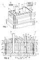
- Fig. 1 is a schematic perspective view of a gear pump constructed in accordance with a first illustrative embodiment of the invention.
- Fig. 2 is a cross sectional view of the gear pump shown in Fig. 1 .
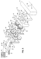
- Fig. 3 is an exploded perspective view of the gear pump shown in Fig. 1 .
- FIG. 1 A first embodiment of a metering gear pump system 10 is schematically shown in Figs. 1-3 .
- System 10 generally includes a metering gear pump 12 coupled for fluid communication with a manifold 14.
- the metering gear pump 12 includes a housing comprising, in this illustrative embodiment, a series of four stacked plates 16, 18, 19, 20, 22. Plates 16, 22 comprise end caps for the metering gear pump 12, while internal plates 18, 19, 20 receive the respective gears, as will be discussed below. Plates 16, 18, 19, 20, 22 are fastened together into a unitary assembly or housing by threaded fasteners 26.
- Plate 18 includes holes or cut-outs 18a, 18b that respectively contain a first, driven gear 30 and a second, idler gear 32.
- the gears 30, 32 have respective gear teeth 30a, 32a in meshing relationship with each other at a central, open area of the plate 18 where the holes 18a, 18b intersect. It will be appreciated that the inventive aspects described herein may be applied to many types of gear pumps, including more complex gear pumps than the examples given herein.
- a drive shaft 40 is directly or indirectly coupled with a motor 42.
- the drive shaft 40 is further coupled to the driven gear 30 by a key 46.
- the idler gear 32 rotates freely about an idler shaft 50 and will be rotated by the driven gear 30 upon activation of the motor 42 due to the meshing relationship of the gear teeth 30a, 32a.
- the respective shafts 40, 50 are received for rotation in holes 16a, 16b of the plate 16.
- Idler shaft 50 is further coupled for rotation relative to a shaft 54.
- Drive shaft 40 is further received for rotation in a journal and seal assembly 55 secured within a hole 22a in plate 22 and a hole 19a in plate 19, and shaft 54 is received for rotation in a hole 57 in plate 22.
- Suitable dynamic seals 59 (schematically illustrated) are used to seal the shafts 40, 50, 54 and prevent leakage of fluid from the pump 12.
- Shaft 54 is connected to a rotatable flow indicating element 60.
- the flow indicating element is a gear 60 having gear teeth 60a.
- the flow indicating element may take other forms of rotatable elements that function as generally described herein.
- Flow indicating gear 60 is coupled to shaft 54 by a key 62.
- Shaft 54 is operatively coupled to a control 70 for indicating rotation of the shaft 54 and the attached flow indicating gear 60 to operating personnel.
- the control 70 may comprise or include an encoder 72 that will detect the rotational speed of the shaft 54 and provide an electronic output indicating that rotational speed.
- shaft 54 is physically connected for rotation with the flow indicating gear 60, the encoder 72 will likewise be indicating the rotational speed of the flow indicating gear 60 for purposes to be described further below.
- Shaft 54 is coupled to shaft 50 by a cylindrical pin 54a contained in a cylindrical blind bore 50a in the end of shaft 50. This connection allows free and independent rotation of the two shafts 50, 54 relative to each other.
- Figs. 1-3 further illustrates a second idler gear 61 that is meshing with gear 60 and rotates with respect to drive shaft 40.
- Gear 61 is not physically keyed or otherwise connected for rotation with drive shaft 40. It will be appreciated that in certain cases, only a single flow indicating element such as gear 60 will be necessary.
- Plate 20 includes a pair of holes or cut-outs 20a, 20b for respectively receiving gears 60, 61.
- Plate 19 is situated between plate 18 and plate 20 and includes holes 19a, 19b for respectively receiving shafts 40, 54, and 19c, 19d respectively in fluid communication with ports 80, 94 of plate 16 (further described below).
- fluid under pressure is supplied from a supply port 76 of the manifold 14 through an inlet port 80 in the plate 16 and into an inlet space 82 between the two gears 30, 32.
- the motor 42 rotates the drive shaft 40 in the direction shown by arrow 84 ( Fig. 3 )
- the meshing gears 30, 32 will rotate in opposite directions as shown by arrows 86, 88. This will create a void or vacuum in the inlet space 82 between the meshing gears 30, 32.
- This inlet space 82 is in communication with the spaces 60b between the gear teeth 60a of the flow indicating gear 60.
- the spaces 60b between the teeth 60a also communicate with the spaces 32b between the teeth 32a of the idler gear 32.
- fluid will be carried by the gear tooth spaces 30b, 32b in the respective holes 18a, 18b of plate 18, as well as in the gear tooth spaces 60b, 61 b in the holes 20a, 20b of plate 20.
- the fluid is directed under pressure from an inlet space 91 to an outlet space 90 in plate 20 as well as an adjacent and communicating outlet space 92 in plate 18.
- the fluid is then forced through the outlet spaces 90, 92 and through a communicating outlet port 94 of plate 16 and a communicating port 96 of the manifold 14 where it is then delivered downstream to further system components (not shown).
- the flow indicating gear 60 and the attached shaft 54 will rotate in the direction of arrow 89 ( Fig. 3 ) at a speed that is proportional to the flow rate of the fluid through the pump 12. This is due to the fluid pressure and the fluid movement around the idler gear 32 and the flow indicating gear 60.
- the control 70 will detect the speed of rotation of shaft 54, which is equal to the speed of rotation of the flow indicating gear 60. If the detected speed is lower than a predetermined level that has been previously determined as indicative of a preset metering rate, then the operating personnel are alerted and/or the system may automatically shut down (e.g., motor 42 may be stopped) so that troubleshooting and maintenance may be performed.
- the alerts may, for example, include one or more lights or audible alarms operatively associated with the control 70.
Landscapes
- Engineering & Computer Science (AREA)
- Mechanical Engineering (AREA)
- General Engineering & Computer Science (AREA)
- Details And Applications Of Rotary Liquid Pumps (AREA)
- Rotary Pumps (AREA)
Applications Claiming Priority (1)
| Application Number | Priority Date | Filing Date | Title |
|---|---|---|---|
| US13/285,514 US8496457B2 (en) | 2011-10-31 | 2011-10-31 | Metering gear pump with integral flow indicator |
Publications (3)
| Publication Number | Publication Date |
|---|---|
| EP2587063A2 true EP2587063A2 (fr) | 2013-05-01 |
| EP2587063A3 EP2587063A3 (fr) | 2015-07-29 |
| EP2587063B1 EP2587063B1 (fr) | 2020-01-01 |
Family
ID=47172440
Family Applications (1)
| Application Number | Title | Priority Date | Filing Date |
|---|---|---|---|
| EP12190804.0A Active EP2587063B1 (fr) | 2011-10-31 | 2012-10-31 | Pompe de mesure à engrenages avec un indicateur intégral |
Country Status (5)
| Country | Link |
|---|---|
| US (1) | US8496457B2 (fr) |
| EP (1) | EP2587063B1 (fr) |
| JP (1) | JP6203487B2 (fr) |
| CN (1) | CN103089613B (fr) |
| ES (1) | ES2776998T3 (fr) |
Cited By (3)
| Publication number | Priority date | Publication date | Assignee | Title |
|---|---|---|---|---|
| WO2017176573A3 (fr) * | 2016-04-04 | 2017-11-02 | Nordson Corporation | Système et procédé de surveillance de l'écoulement d'un adhésif liquide |
| WO2018114919A1 (fr) * | 2016-12-21 | 2018-06-28 | Robert Bosch Gmbh | Pompe à engrenages extérieurs pour système de récuperation de chaleur perdue |
| US12000139B2 (en) | 2019-04-14 | 2024-06-04 | Building Envelope Materials LLC | Insulation injection device |
Families Citing this family (7)
| Publication number | Priority date | Publication date | Assignee | Title |
|---|---|---|---|---|
| US9441998B2 (en) * | 2014-07-21 | 2016-09-13 | Ecolab Usa Inc. | Oval gear meter |
| US10695779B2 (en) | 2016-09-08 | 2020-06-30 | Nordson Corporation | Applicator having active backpressure control devices |
| ES2847950T3 (es) | 2016-09-08 | 2021-08-04 | Nordson Corp | Aplicador con placa de desvío |
| WO2019148007A1 (fr) * | 2018-01-26 | 2019-08-01 | Waterblasting, Llc | Pompe pour matières thermoplastiques fondues |
| US10982670B2 (en) * | 2019-01-22 | 2021-04-20 | GM Global Technology Operations LLC | Gear pump and gear assembly |
| US11525444B2 (en) | 2020-09-30 | 2022-12-13 | GM Global Technology Operations LLC | Scavenge gear plate for improved flow |
| DE102021116160A1 (de) * | 2021-06-22 | 2022-12-22 | Fte Automotive Gmbh | Zahnradpumpe und Antriebsmaschine |
Family Cites Families (16)
| Publication number | Priority date | Publication date | Assignee | Title |
|---|---|---|---|---|
| FR2163935A5 (fr) * | 1971-12-07 | 1973-07-27 | Rhone Poulenc Sa | |
| US4193745A (en) | 1978-03-09 | 1980-03-18 | Nordson Corporation | Gear pump with means for dispersing gas into liquid |
| US5244367A (en) * | 1990-11-30 | 1993-09-14 | Aeroquip Corporation | Gear pump with a resilient means for biasing a side wear plate |
| US5228594A (en) * | 1990-11-30 | 1993-07-20 | Aeroquip Corporation | Metered liquid dispensing system |
| JP3356308B2 (ja) * | 1992-08-25 | 2002-12-16 | 三菱レイヨン株式会社 | ギヤ式定量ポンプ |
| CN1096570A (zh) * | 1993-06-14 | 1994-12-21 | 赵明 | 圆弧点啮合齿轮泵 |
| US5727933A (en) * | 1995-12-20 | 1998-03-17 | Hale Fire Pump Company | Pump and flow sensor combination |
| US5829647A (en) | 1996-07-23 | 1998-11-03 | Nordson Corporation | Metering gearhead dispensing apparatus having selectively positionable gear pumps |
| US5992230A (en) * | 1997-11-15 | 1999-11-30 | Hoffer Flow Controls, Inc. | Dual rotor flow meter |
| US6131770A (en) * | 1998-10-15 | 2000-10-17 | Nordson Corporation | Hot melt delivery system |
| WO2001086150A1 (fr) * | 2000-05-08 | 2001-11-15 | Pomtava Sa | Pompe de dosage pour produits liquides |
| US6685054B2 (en) * | 2000-08-09 | 2004-02-03 | Sanyo Electric Co., Ltd. | Apparatus and method for delivering liquids |
| JP4666836B2 (ja) * | 2000-08-09 | 2011-04-06 | 三洋電機株式会社 | 液体送出装置および液体送出方法 |
| US6759969B2 (en) * | 2001-06-01 | 2004-07-06 | Tuthill Corporation | Fiberoptic transceiver system |
| JP2006097568A (ja) * | 2004-09-29 | 2006-04-13 | Shimadzu Corp | 二連歯車ポンプ |
| US7851775B2 (en) * | 2005-09-29 | 2010-12-14 | The United States Of America As Represented By The Secretary Of The Army | Gear-type drink-o-meter to monitor fluid consumption |
-
2011
- 2011-10-31 US US13/285,514 patent/US8496457B2/en not_active Expired - Fee Related
-
2012
- 2012-10-31 JP JP2012239688A patent/JP6203487B2/ja not_active Expired - Fee Related
- 2012-10-31 EP EP12190804.0A patent/EP2587063B1/fr active Active
- 2012-10-31 ES ES12190804T patent/ES2776998T3/es active Active
- 2012-10-31 CN CN201210505952.XA patent/CN103089613B/zh not_active Expired - Fee Related
Non-Patent Citations (1)
| Title |
|---|
| None |
Cited By (5)
| Publication number | Priority date | Publication date | Assignee | Title |
|---|---|---|---|---|
| WO2017176573A3 (fr) * | 2016-04-04 | 2017-11-02 | Nordson Corporation | Système et procédé de surveillance de l'écoulement d'un adhésif liquide |
| US11041745B2 (en) | 2016-04-04 | 2021-06-22 | Nordson Corporation | System and method for monitoring liquid adhesive flow |
| US12038313B2 (en) | 2016-04-04 | 2024-07-16 | Nordson Corporation | System and method for monitoring liquid adhesive flow |
| WO2018114919A1 (fr) * | 2016-12-21 | 2018-06-28 | Robert Bosch Gmbh | Pompe à engrenages extérieurs pour système de récuperation de chaleur perdue |
| US12000139B2 (en) | 2019-04-14 | 2024-06-04 | Building Envelope Materials LLC | Insulation injection device |
Also Published As
| Publication number | Publication date |
|---|---|
| EP2587063A3 (fr) | 2015-07-29 |
| ES2776998T3 (es) | 2020-08-03 |
| EP2587063B1 (fr) | 2020-01-01 |
| JP2013096415A (ja) | 2013-05-20 |
| US8496457B2 (en) | 2013-07-30 |
| US20130108494A1 (en) | 2013-05-02 |
| JP6203487B2 (ja) | 2017-09-27 |
| CN103089613B (zh) | 2017-04-12 |
| CN103089613A (zh) | 2013-05-08 |
Similar Documents
| Publication | Publication Date | Title |
|---|---|---|
| US8496457B2 (en) | Metering gear pump with integral flow indicator | |
| EP1429029B1 (fr) | Assemblage de distributeur de colle thermofusible comprenant des ensembles indépendants de pompe à engrenage | |
| US5727933A (en) | Pump and flow sensor combination | |
| US5667368A (en) | Diaphragm metering pump including improved leak detection diaphragm | |
| EP2572076B1 (fr) | Pompe ou segment de dosage et ensemble pompe de dosage comprenant une pluralité de pompes ou de segments de dosage | |
| JPH08292078A (ja) | 一体ポンプ・流量計装置 | |
| US20130319153A1 (en) | Flow and pressure ripple reduction with advance dual gear and bearing face cut | |
| US20090068034A1 (en) | Pumping system with precise ratio output | |
| EP3746659B1 (fr) | Appareil de pompe à déplacement positif à canaux multiples | |
| CA2311098C (fr) | Systeme de pompage servant a injecter des quantites mesurees de fluide dans un flux liquide | |
| CN103967782B (zh) | 双向三齿轮泵 | |
| KR101453429B1 (ko) | 고압의 고점도 액 이송을 위한 이액형 복렬구조의 트로코이드 펌프 | |
| EP1937974B1 (fr) | Station de mesure d'adhesif thermofusible a distance | |
| EP1039121A2 (fr) | Pompe à carburant | |
| US3715177A (en) | Fluid metering apparatus | |
| CN204710660U (zh) | 中线胶供给系统 | |
| US20120018454A1 (en) | rotary metering device and system | |
| EP0593125A1 (fr) | Diviseur de courant liquide | |
| JP2021067243A (ja) | 定量ポンプ駆動装置と塗工装置 | |
| CN115324893A (zh) | 一种油田专用油气混输撬装 | |
| CN117490790A (zh) | 一种新型内齿轮流量计 | |
| HK1165546A (en) | A rotary metering device and system |
Legal Events
| Date | Code | Title | Description |
|---|---|---|---|
| PUAI | Public reference made under article 153(3) epc to a published international application that has entered the european phase |
Free format text: ORIGINAL CODE: 0009012 |
|
| AK | Designated contracting states |
Kind code of ref document: A2 Designated state(s): AL AT BE BG CH CY CZ DE DK EE ES FI FR GB GR HR HU IE IS IT LI LT LU LV MC MK MT NL NO PL PT RO RS SE SI SK SM TR |
|
| AX | Request for extension of the european patent |
Extension state: BA ME |
|
| PUAL | Search report despatched |
Free format text: ORIGINAL CODE: 0009013 |
|
| AK | Designated contracting states |
Kind code of ref document: A3 Designated state(s): AL AT BE BG CH CY CZ DE DK EE ES FI FR GB GR HR HU IE IS IT LI LT LU LV MC MK MT NL NO PL PT RO RS SE SI SK SM TR |
|
| AX | Request for extension of the european patent |
Extension state: BA ME |
|
| RIC1 | Information provided on ipc code assigned before grant |
Ipc: F04C 2/18 20060101AFI20150622BHEP Ipc: F04C 14/28 20060101ALI20150622BHEP |
|
| 17P | Request for examination filed |
Effective date: 20160129 |
|
| RBV | Designated contracting states (corrected) |
Designated state(s): AL AT BE BG CH CY CZ DE DK EE ES FI FR GB GR HR HU IE IS IT LI LT LU LV MC MK MT NL NO PL PT RO RS SE SI SK SM TR |
|
| STAA | Information on the status of an ep patent application or granted ep patent |
Free format text: STATUS: EXAMINATION IS IN PROGRESS |
|
| 17Q | First examination report despatched |
Effective date: 20161206 |
|
| GRAP | Despatch of communication of intention to grant a patent |
Free format text: ORIGINAL CODE: EPIDOSNIGR1 |
|
| STAA | Information on the status of an ep patent application or granted ep patent |
Free format text: STATUS: GRANT OF PATENT IS INTENDED |
|
| INTG | Intention to grant announced |
Effective date: 20190711 |
|
| GRAS | Grant fee paid |
Free format text: ORIGINAL CODE: EPIDOSNIGR3 |
|
| GRAA | (expected) grant |
Free format text: ORIGINAL CODE: 0009210 |
|
| STAA | Information on the status of an ep patent application or granted ep patent |
Free format text: STATUS: THE PATENT HAS BEEN GRANTED |
|
| AK | Designated contracting states |
Kind code of ref document: B1 Designated state(s): AL AT BE BG CH CY CZ DE DK EE ES FI FR GB GR HR HU IE IS IT LI LT LU LV MC MK MT NL NO PL PT RO RS SE SI SK SM TR |
|
| REG | Reference to a national code |
Ref country code: GB Ref legal event code: FG4D |
|
| REG | Reference to a national code |
Ref country code: CH Ref legal event code: EP Ref country code: AT Ref legal event code: REF Ref document number: 1220091 Country of ref document: AT Kind code of ref document: T Effective date: 20200115 |
|
| REG | Reference to a national code |
Ref country code: IE Ref legal event code: FG4D |
|
| REG | Reference to a national code |
Ref country code: DE Ref legal event code: R096 Ref document number: 602012066857 Country of ref document: DE |
|
| REG | Reference to a national code |
Ref country code: NL Ref legal event code: MP Effective date: 20200101 |
|
| REG | Reference to a national code |
Ref country code: LT Ref legal event code: MG4D |
|
| PG25 | Lapsed in a contracting state [announced via postgrant information from national office to epo] |
Ref country code: RS Free format text: LAPSE BECAUSE OF FAILURE TO SUBMIT A TRANSLATION OF THE DESCRIPTION OR TO PAY THE FEE WITHIN THE PRESCRIBED TIME-LIMIT Effective date: 20200101 Ref country code: FI Free format text: LAPSE BECAUSE OF FAILURE TO SUBMIT A TRANSLATION OF THE DESCRIPTION OR TO PAY THE FEE WITHIN THE PRESCRIBED TIME-LIMIT Effective date: 20200101 Ref country code: NO Free format text: LAPSE BECAUSE OF FAILURE TO SUBMIT A TRANSLATION OF THE DESCRIPTION OR TO PAY THE FEE WITHIN THE PRESCRIBED TIME-LIMIT Effective date: 20200401 Ref country code: LT Free format text: LAPSE BECAUSE OF FAILURE TO SUBMIT A TRANSLATION OF THE DESCRIPTION OR TO PAY THE FEE WITHIN THE PRESCRIBED TIME-LIMIT Effective date: 20200101 Ref country code: NL Free format text: LAPSE BECAUSE OF FAILURE TO SUBMIT A TRANSLATION OF THE DESCRIPTION OR TO PAY THE FEE WITHIN THE PRESCRIBED TIME-LIMIT Effective date: 20200101 Ref country code: CZ Free format text: LAPSE BECAUSE OF FAILURE TO SUBMIT A TRANSLATION OF THE DESCRIPTION OR TO PAY THE FEE WITHIN THE PRESCRIBED TIME-LIMIT Effective date: 20200101 Ref country code: PT Free format text: LAPSE BECAUSE OF FAILURE TO SUBMIT A TRANSLATION OF THE DESCRIPTION OR TO PAY THE FEE WITHIN THE PRESCRIBED TIME-LIMIT Effective date: 20200527 |
|
| REG | Reference to a national code |
Ref country code: ES Ref legal event code: FG2A Ref document number: 2776998 Country of ref document: ES Kind code of ref document: T3 Effective date: 20200803 |
|
| PG25 | Lapsed in a contracting state [announced via postgrant information from national office to epo] |
Ref country code: SE Free format text: LAPSE BECAUSE OF FAILURE TO SUBMIT A TRANSLATION OF THE DESCRIPTION OR TO PAY THE FEE WITHIN THE PRESCRIBED TIME-LIMIT Effective date: 20200101 Ref country code: LV Free format text: LAPSE BECAUSE OF FAILURE TO SUBMIT A TRANSLATION OF THE DESCRIPTION OR TO PAY THE FEE WITHIN THE PRESCRIBED TIME-LIMIT Effective date: 20200101 Ref country code: HR Free format text: LAPSE BECAUSE OF FAILURE TO SUBMIT A TRANSLATION OF THE DESCRIPTION OR TO PAY THE FEE WITHIN THE PRESCRIBED TIME-LIMIT Effective date: 20200101 Ref country code: IS Free format text: LAPSE BECAUSE OF FAILURE TO SUBMIT A TRANSLATION OF THE DESCRIPTION OR TO PAY THE FEE WITHIN THE PRESCRIBED TIME-LIMIT Effective date: 20200501 Ref country code: BG Free format text: LAPSE BECAUSE OF FAILURE TO SUBMIT A TRANSLATION OF THE DESCRIPTION OR TO PAY THE FEE WITHIN THE PRESCRIBED TIME-LIMIT Effective date: 20200401 Ref country code: GR Free format text: LAPSE BECAUSE OF FAILURE TO SUBMIT A TRANSLATION OF THE DESCRIPTION OR TO PAY THE FEE WITHIN THE PRESCRIBED TIME-LIMIT Effective date: 20200402 |
|
| REG | Reference to a national code |
Ref country code: DE Ref legal event code: R097 Ref document number: 602012066857 Country of ref document: DE |
|
| PG25 | Lapsed in a contracting state [announced via postgrant information from national office to epo] |
Ref country code: SK Free format text: LAPSE BECAUSE OF FAILURE TO SUBMIT A TRANSLATION OF THE DESCRIPTION OR TO PAY THE FEE WITHIN THE PRESCRIBED TIME-LIMIT Effective date: 20200101 Ref country code: RO Free format text: LAPSE BECAUSE OF FAILURE TO SUBMIT A TRANSLATION OF THE DESCRIPTION OR TO PAY THE FEE WITHIN THE PRESCRIBED TIME-LIMIT Effective date: 20200101 Ref country code: DK Free format text: LAPSE BECAUSE OF FAILURE TO SUBMIT A TRANSLATION OF THE DESCRIPTION OR TO PAY THE FEE WITHIN THE PRESCRIBED TIME-LIMIT Effective date: 20200101 Ref country code: EE Free format text: LAPSE BECAUSE OF FAILURE TO SUBMIT A TRANSLATION OF THE DESCRIPTION OR TO PAY THE FEE WITHIN THE PRESCRIBED TIME-LIMIT Effective date: 20200101 Ref country code: SM Free format text: LAPSE BECAUSE OF FAILURE TO SUBMIT A TRANSLATION OF THE DESCRIPTION OR TO PAY THE FEE WITHIN THE PRESCRIBED TIME-LIMIT Effective date: 20200101 |
|
| PLBE | No opposition filed within time limit |
Free format text: ORIGINAL CODE: 0009261 |
|
| STAA | Information on the status of an ep patent application or granted ep patent |
Free format text: STATUS: NO OPPOSITION FILED WITHIN TIME LIMIT |
|
| REG | Reference to a national code |
Ref country code: AT Ref legal event code: MK05 Ref document number: 1220091 Country of ref document: AT Kind code of ref document: T Effective date: 20200101 |
|
| 26N | No opposition filed |
Effective date: 20201002 |
|
| PG25 | Lapsed in a contracting state [announced via postgrant information from national office to epo] |
Ref country code: AT Free format text: LAPSE BECAUSE OF FAILURE TO SUBMIT A TRANSLATION OF THE DESCRIPTION OR TO PAY THE FEE WITHIN THE PRESCRIBED TIME-LIMIT Effective date: 20200101 |
|
| PG25 | Lapsed in a contracting state [announced via postgrant information from national office to epo] |
Ref country code: SI Free format text: LAPSE BECAUSE OF FAILURE TO SUBMIT A TRANSLATION OF THE DESCRIPTION OR TO PAY THE FEE WITHIN THE PRESCRIBED TIME-LIMIT Effective date: 20200101 Ref country code: PL Free format text: LAPSE BECAUSE OF FAILURE TO SUBMIT A TRANSLATION OF THE DESCRIPTION OR TO PAY THE FEE WITHIN THE PRESCRIBED TIME-LIMIT Effective date: 20200101 |
|
| REG | Reference to a national code |
Ref country code: DE Ref legal event code: R119 Ref document number: 602012066857 Country of ref document: DE |
|
| REG | Reference to a national code |
Ref country code: CH Ref legal event code: PL |
|
| GBPC | Gb: european patent ceased through non-payment of renewal fee |
Effective date: 20201031 |
|
| PG25 | Lapsed in a contracting state [announced via postgrant information from national office to epo] |
Ref country code: MC Free format text: LAPSE BECAUSE OF FAILURE TO SUBMIT A TRANSLATION OF THE DESCRIPTION OR TO PAY THE FEE WITHIN THE PRESCRIBED TIME-LIMIT Effective date: 20200101 Ref country code: LU Free format text: LAPSE BECAUSE OF NON-PAYMENT OF DUE FEES Effective date: 20201031 |
|
| REG | Reference to a national code |
Ref country code: BE Ref legal event code: MM Effective date: 20201031 |
|
| PG25 | Lapsed in a contracting state [announced via postgrant information from national office to epo] |
Ref country code: DE Free format text: LAPSE BECAUSE OF NON-PAYMENT OF DUE FEES Effective date: 20210501 Ref country code: FR Free format text: LAPSE BECAUSE OF NON-PAYMENT OF DUE FEES Effective date: 20201031 |
|
| PG25 | Lapsed in a contracting state [announced via postgrant information from national office to epo] |
Ref country code: BE Free format text: LAPSE BECAUSE OF NON-PAYMENT OF DUE FEES Effective date: 20201031 Ref country code: CH Free format text: LAPSE BECAUSE OF NON-PAYMENT OF DUE FEES Effective date: 20201031 Ref country code: GB Free format text: LAPSE BECAUSE OF NON-PAYMENT OF DUE FEES Effective date: 20201031 Ref country code: LI Free format text: LAPSE BECAUSE OF NON-PAYMENT OF DUE FEES Effective date: 20201031 |
|
| PG25 | Lapsed in a contracting state [announced via postgrant information from national office to epo] |
Ref country code: IE Free format text: LAPSE BECAUSE OF NON-PAYMENT OF DUE FEES Effective date: 20201031 |
|
| REG | Reference to a national code |
Ref country code: ES Ref legal event code: FD2A Effective date: 20220128 |
|
| PG25 | Lapsed in a contracting state [announced via postgrant information from national office to epo] |
Ref country code: IT Free format text: LAPSE BECAUSE OF NON-PAYMENT OF DUE FEES Effective date: 20201031 |
|
| PG25 | Lapsed in a contracting state [announced via postgrant information from national office to epo] |
Ref country code: TR Free format text: LAPSE BECAUSE OF FAILURE TO SUBMIT A TRANSLATION OF THE DESCRIPTION OR TO PAY THE FEE WITHIN THE PRESCRIBED TIME-LIMIT Effective date: 20200101 Ref country code: MT Free format text: LAPSE BECAUSE OF FAILURE TO SUBMIT A TRANSLATION OF THE DESCRIPTION OR TO PAY THE FEE WITHIN THE PRESCRIBED TIME-LIMIT Effective date: 20200101 Ref country code: ES Free format text: LAPSE BECAUSE OF NON-PAYMENT OF DUE FEES Effective date: 20201101 Ref country code: CY Free format text: LAPSE BECAUSE OF FAILURE TO SUBMIT A TRANSLATION OF THE DESCRIPTION OR TO PAY THE FEE WITHIN THE PRESCRIBED TIME-LIMIT Effective date: 20200101 |
|
| PG25 | Lapsed in a contracting state [announced via postgrant information from national office to epo] |
Ref country code: MK Free format text: LAPSE BECAUSE OF FAILURE TO SUBMIT A TRANSLATION OF THE DESCRIPTION OR TO PAY THE FEE WITHIN THE PRESCRIBED TIME-LIMIT Effective date: 20200101 Ref country code: AL Free format text: LAPSE BECAUSE OF FAILURE TO SUBMIT A TRANSLATION OF THE DESCRIPTION OR TO PAY THE FEE WITHIN THE PRESCRIBED TIME-LIMIT Effective date: 20200101 |