EP2587064A1 - Flügelzellen-Vakuumpumpe - Google Patents
Flügelzellen-Vakuumpumpe Download PDFInfo
- Publication number
- EP2587064A1 EP2587064A1 EP11186917.8A EP11186917A EP2587064A1 EP 2587064 A1 EP2587064 A1 EP 2587064A1 EP 11186917 A EP11186917 A EP 11186917A EP 2587064 A1 EP2587064 A1 EP 2587064A1
- Authority
- EP
- European Patent Office
- Prior art keywords
- sector
- pump
- vacuum pump
- vane vacuum
- outlet
- Prior art date
- Legal status (The legal status is an assumption and is not a legal conclusion. Google has not performed a legal analysis and makes no representation as to the accuracy of the status listed.)
- Granted
Links
Images
Classifications
-
- F—MECHANICAL ENGINEERING; LIGHTING; HEATING; WEAPONS; BLASTING
- F01—MACHINES OR ENGINES IN GENERAL; ENGINE PLANTS IN GENERAL; STEAM ENGINES
- F01C—ROTARY-PISTON OR OSCILLATING-PISTON MACHINES OR ENGINES
- F01C21/00—Component parts, details or accessories not provided for in groups F01C1/00 - F01C20/00
- F01C21/10—Outer members for co-operation with rotary pistons; Casings
- F01C21/104—Stators; Members defining the outer boundaries of the working chamber
- F01C21/106—Stators; Members defining the outer boundaries of the working chamber with a radial surface, e.g. cam rings
-
- F—MECHANICAL ENGINEERING; LIGHTING; HEATING; WEAPONS; BLASTING
- F04—POSITIVE - DISPLACEMENT MACHINES FOR LIQUIDS; PUMPS FOR LIQUIDS OR ELASTIC FLUIDS
- F04C—ROTARY-PISTON, OR OSCILLATING-PISTON, POSITIVE-DISPLACEMENT MACHINES FOR LIQUIDS; ROTARY-PISTON, OR OSCILLATING-PISTON, POSITIVE-DISPLACEMENT PUMPS
- F04C18/00—Rotary-piston pumps specially adapted for elastic fluids
- F04C18/30—Rotary-piston pumps specially adapted for elastic fluids having the characteristics covered by two or more of groups F04C18/02, F04C18/08, F04C18/22, F04C18/24, F04C18/48, or having the characteristics covered by one of these groups together with some other type of movement between co-operating members
- F04C18/34—Rotary-piston pumps specially adapted for elastic fluids having the characteristics covered by two or more of groups F04C18/02, F04C18/08, F04C18/22, F04C18/24, F04C18/48, or having the characteristics covered by one of these groups together with some other type of movement between co-operating members having the movement defined in group F04C18/08 or F04C18/22 and relative reciprocation between the co-operating members
- F04C18/344—Rotary-piston pumps specially adapted for elastic fluids having the characteristics covered by two or more of groups F04C18/02, F04C18/08, F04C18/22, F04C18/24, F04C18/48, or having the characteristics covered by one of these groups together with some other type of movement between co-operating members having the movement defined in group F04C18/08 or F04C18/22 and relative reciprocation between the co-operating members with vanes reciprocating with respect to the inner member
- F04C18/3441—Rotary-piston pumps specially adapted for elastic fluids having the characteristics covered by two or more of groups F04C18/02, F04C18/08, F04C18/22, F04C18/24, F04C18/48, or having the characteristics covered by one of these groups together with some other type of movement between co-operating members having the movement defined in group F04C18/08 or F04C18/22 and relative reciprocation between the co-operating members with vanes reciprocating with respect to the inner member the inner and outer member being in contact along one line or continuous surface substantially parallel to the axis of rotation
-
- F—MECHANICAL ENGINEERING; LIGHTING; HEATING; WEAPONS; BLASTING
- F04—POSITIVE - DISPLACEMENT MACHINES FOR LIQUIDS; PUMPS FOR LIQUIDS OR ELASTIC FLUIDS
- F04C—ROTARY-PISTON, OR OSCILLATING-PISTON, POSITIVE-DISPLACEMENT MACHINES FOR LIQUIDS; ROTARY-PISTON, OR OSCILLATING-PISTON, POSITIVE-DISPLACEMENT PUMPS
- F04C2220/00—Application
- F04C2220/10—Vacuum
- F04C2220/12—Dry running
-
- F—MECHANICAL ENGINEERING; LIGHTING; HEATING; WEAPONS; BLASTING
- F04—POSITIVE - DISPLACEMENT MACHINES FOR LIQUIDS; PUMPS FOR LIQUIDS OR ELASTIC FLUIDS
- F04C—ROTARY-PISTON, OR OSCILLATING-PISTON, POSITIVE-DISPLACEMENT MACHINES FOR LIQUIDS; ROTARY-PISTON, OR OSCILLATING-PISTON, POSITIVE-DISPLACEMENT PUMPS
- F04C2250/00—Geometry
- F04C2250/30—Geometry of the stator
- F04C2250/301—Geometry of the stator compression chamber profile defined by a mathematical expression or by parameters
Definitions
- the invention relates to a vane vacuum pump for generating a negative pressure of 100 mbar absolute and less in a motor vehicle.
- Such vacuum pumps are used in motor vehicles to provide the working pressure for other units available, for example, for a brake booster.
- Automotive vacuum pumps are usually so-called vane vacuum pumps in which at least three slidably mounted in a rotor body slider divides the pump chamber into a corresponding number of rotating pump cells.
- Conventional automotive vane vacuum pumps have a pump chamber having a circular cross-section with a correspondingly circular peripheral wall.
- the circularity of the pumping space has the geometric consequence that the volume of the rotating pumping cells always changes.
- a tangential force is caused on the slider, by which the slider is tilted in the circumferential direction, so that corresponding clamping forces between the slider and the Schleberschlitz are generated in the rotor body.
- These clamping forces in turn consume a portion of the drive energy and are also responsible for increased wear of the slide.
- the object of the invention is to provide a motor vehicle vane vacuum pump with reduced slide wear and reduced friction losses.
- the pump space is divided into a plurality of rotating pump cells with a same cell sector angle ⁇ .
- the peripheral wall of the pump housing, which defines the pump space radially, is not circular, but has an isovolumector sector b with a constant radius to the rotor axial, wherein the pump rotor is arranged eccentrically to the center of gravity of the pump chamber surface.
- the isovolumometric vector b is at least 10 ° greater than the cell sector angle ⁇ .
- the Isovolumetriesektor b is at least 20 ° larger, and most preferably at least 30 ° greater than the cell sector angle a.
- the pumping cell traveling through the isovoluminescent sector thus does not change its volume over an angle of at least 10 ° or 20 or 30 °, ie it moves isovolumetrically in this sector.
- the pumping cell In the region of the isovolumometric vector, the pumping cell is fluidically closed, i. the pump cell is not connected to either the inlet port or the outlet port.
- the isovoluminescent sector is arranged in the direction of rotation between the inlet sector with the inlet opening and the outlet sector with the outlet opening.
- the sliders are furthest out of the corresponding slide slots of the rotor body, so that even relatively small pressure differences between the two sides of the slide generate considerable tilting forces which generate corresponding clamping forces.
- the isovoluximetry sector can also be arranged in the direction of rotation between the outlet sector and the inlet sector.
- an electric motor for driving the pump rotor is provided.
- the drive of the vacuum pump by an electric motor is particularly advantageous because the speed of the vacuum pump is then not directly dependent on the speed of the motor vehicle drive motor. Rather, in a simple embodiment, the electric motor can rotate the vacuum pump at an approximately constant speed, or, in a more elaborate embodiment, adapt the speed of the vacuum pump to the boundary conditions.
- the vacuum pump is designed to run dry, so that no liquid pump lubrication is provided.
- This design is constructively simple and inexpensive.
- only a suitably suitable, low-friction material pairing has to be selected for the slide head on the one hand and the peripheral wall on the other hand.
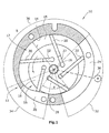
- each is a vane vacuum pump 10; 10 ', which is intended for use in a motor vehicle and can produce an absolute pressure of 100 mbar and less.
- the vacuum pump 10 of FIG. 1 has a pump housing 12, which encloses a pump chamber 17 substantially.
- the pump housing 12 consists essentially of a non-circular peripheral wall 14 and two lids 15, wherein in both figures, the overhead lid is not visible because of the representation in cross section.
- a pump rotor 16 is arranged eccentrically to the center of gravity of the pump chamber 17 rotatably.
- the pump rotor 16 has a rotor body 18 and five slides 20 which are slidably mounted in corresponding slide slots 22 of the rotor body 18 with a radial component.
- the rotor body 18 is arranged such that at one point the peripheral wall 14 between the outlet opening 26 and The inlet opening 24, a sealing gap 28 is formed with a gap height of about 0.1 mm, which largely prevents a gas back flow from the outlet opening 26 to the inlet opening 24.
- the five slides 20 divide the pumping space 17 into five rotating pumping cells, each having the same line sector angle ⁇ , which in the present case is approximately 72 °.
- the pump rotor 16 rotates about a rotor axis 19 and is driven by an electric motor 30.
- the pumping space 17 can be divided into a plurality of sectors, namely an inlet sector 32 with an inlet opening 24, an outlet sector 34 with an outlet opening 26 and an isovolumimetric sector 36 arranged in the direction of rotation of the motor 16 between the inlet sector 32 and the outlet sector 34.
- the isovolumectomy 36 of the FIG. 1 extends over an angle b of about 160 °, that is about 90 ° greater than the cell sector angle a of 72 °.
- the radius r of the peripheral wall 14 to the rotor axis 19 is constant over the entire Isovolumetriesektor- angle b, so that the cell volume of the pump cell in the region of Isovolumetriesektors 36 is constant and does not change.
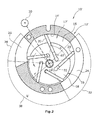
- the isovolumector sector 38 is arranged in the direction of rotation between the outlet sector 34 and the inlet sector 32.
- the radius r 'of the peripheral wall 14' in the region of Isovolumetriesektors 38 is also constant here and approximately corresponds to the outer radius of the circular cross-section rotor body 18.
Landscapes
- Engineering & Computer Science (AREA)
- Mechanical Engineering (AREA)
- General Engineering & Computer Science (AREA)
- Applications Or Details Of Rotary Compressors (AREA)
- Rotary Pumps (AREA)
Abstract
Description
- Die Erfindung bezieht sich auf eine Flügelzellen-Vakuumpumpe zur Erzeugung eines Unterdruckes von absolut 100 mbar und weniger in einem Kraftfahrzeug.
- Derartige Vakuumpumpen dienen in Kraftfahrzeugen dazu, den Arbeitsdruck für andere Aggregate zur Verfügung zu stellen, beispielsweise für einen Bremskraftverstärker.
- Kfz-Vakuumpumpen sind in aller Regel so genannte Flügelzellen-Vakuumpumpen, bei denen mindestens drei in einem Rotorkörper verschiebbar gelagerte Schieber den Pumpraum in entsprechend viele rotierende Pumpzellen teilt. Herkömmliche Kfz-Flügelzellen-Vakuumpumpen weisen einen im Querschnitt kreisförmigen Pumpraum mit einer entsprechend kreisförmig geformten Umfangswand auf. Die Kreisförmigkeit des Pumpraums hat geometrisch zur Folge, dass sich das Volumen der rotierenden Pumpzellen stets ändert. Hierdurch liegt zwischen zwei benachbarten Pumpzellen, die durch den betreffenden Schieber voneinander getrennt sind, stets ein mehr oder weniger großes Druckgefälle vor. Durch dieses Druckgefälle wird eine tangentiale Kraft auf den Schieber verursacht, durch die der Schieber in Umfangsrichtung verkippt wird, so dass entsprechende Klemmkräfte zwischen dem Schieber und dem Schleberschlitz in dem Rotorkörper generiert werden. Diese Klemmkräfte wiederum verzehren einen Teil der Antriebsenergie und sind auch für einen erhöhten Verschleiß der Schieber verantwortlich.
- Aufgabe der Erfindung ist es vor diesem Hintergrund, eine Kfz-Flügelzellen-Vakuumpumpe mit verringertem Schieber-Verschleiß und verringerten Reibungsverlusten zu schaffen.
- Diese Aufgabe wird erfindungsgemäß gelöst mit einer Vakuumpumpe mit den Merkmalen des Patentanspruchs 1.
- Durch die Schieber wird der Pumpraum in mehrere rotierende Pumpzellen mit einem gleichen Zellensektorwinkel a geteilt. Die Umfangswand des Pumpengehäuses, die den Pumpraum radial begrenzt, ist nicht kreisförmig ausgebildet, sondern weist einen Isovolumetriesektor b mit einem konstanten Radius zur Rotoraxialen auf, wobei der Pumpenrotor exzentrisch zum Schwerpunkt der Pumpraum-Fläche angeordnet ist. Der Isovolumetriesektor b ist mindestens 10° größer als der Zellensektorwinkel a. Besonders bevorzugt ist der Isovolumetriesektor b mindestens 20° größer, und ganz besonders bevorzugt mindestens 30° größer als der Zellensektorwinkel a.
- Die durch den Isovolumetriesektor wandernde Pumpzelle ändert ihr Volumen auf diese Weise über einen Winkel von mindestens 10° bzw. 20 oder 30° nicht, bewegt sich also in diesem Sektor isovolumetrisch. Im Bereich des Isovolumetriesektors ist die Pumpzelle fluidisch geschlossen, d.h. die Pumpzelle ist weder mit der Einlassöffnung noch mit der Auslassöffnung verbunden.
- Im Bereich des Isovolumetriesektors herrschen zwischen zwei benachbarten Pumpzellen gleiche Drücke, so dass keine tangentialen Kräfte generiert werden. Da keine durch entsprechende Druckdifferenzen erzeugten Kippkräfte auf den Schieber wirken, wird der Schieber nicht verkippt. Untersuchungen ergeben haben, dass hierdurch Antriebsenergie eingespart und der Verschleiß der Schieber reduziert wird.
- Vorzugsweise ist der Isovolumetriesektor in Drehrichtung zwischen dem Einlasssektor mit der Einlassöffnung und dem Auslasssektor mit der Auslassöffnung angeordnet. In diesen Bereich zwischen dem Einlasssektor und dem Auslasssektor sind die Schieber am weitesten herausgefahren aus den entsprechenden Schieberschlitzen des Rotorkörpers, so dass bereits relativ geringe Druckunterschiede zwischen den beiden Seiten des Schiebers erhebliche Kippkräfte generieren, die entsprechende Klemmkräfte erzeugen. Durch die Anordnung des Isovolumetriesektors in Drehrichtung zwischen dem Einlasssektor und dem Auslasssektor wird die Generierung besonders hoher unerwünschter Kippkräfte bzw. Kippmomente vermieden.
- Alternativ oder ergänzend zu der Anordnung des Isovolumetriesektors zwischen dem Einlasssektor und dem Auslasssektor kann der Isovolumetriesektor auch in Drehrichtung zwischen dem Auslasssektor und dem Einlasssektor angeordnet werden.
- Gemäß einer bevorzugten Ausgestaltung ist ein Elektromotor zum Antrieb des Pumpenrotors vorgesehen. Der Antrieb der Vakuumpumpe durch einen Elektromotor ist insbesondere deshalb vorteilhaft, weil die Drehzahl der Vakuumpumpe dann nicht unmittelbar von der Drehzahl des Kfz-Antriebsmotors abhängig ist. Vielmehr kann der Elektromotor in einer einfachen Ausführung die Vakuumpumpe mit einer annähernd konstanten Drehzahl drehen, oder aber, in einer aufwändigeren Ausführung, die Drehzahl der Vakuumpumpe den Randbedingungen anpassen.
- Vorzugsweise ist die Vakuumpumpe trockenlaufend ausgebildet, so dass keine liquide Pumpenschmierung vorgesehen ist. Diese Ausführung ist konstruktiv einfach und preiswert. Es muss für die Schieberköpfe einerseits und die Umfangswand andererseits lediglich eine entsprechend geeignete reibungsarme Werkstoffpaarung gewählt werden.
- Im Folgenden werden zwei Ausführungsbeispiele der Erfindung anhand der Zeichnungen näher erläutert. Es zeigen:
-
Figur 1 ein erstes Ausführungsbeispiel eines Querschnitts einer Kfz-Flügelzellen-Vakuumpumpe mit einem Isovolumetriesektor zwischen dem Einlasssektor und dem Auslasssektor, und -
Figur 2 ein zweites Ausführungsbeispiel eines Querschnitts einer Kfz-Flügelzellen-Vakuumpumpe mit einem Isovolumetriesektor zwischen dem Auslasssektor und dem Einlasssektor. - In den
Figuren 1 und2 ist jeweils eine Flügelzellen-Vakuumpumpe 10; 10' dargestellt, die für den Einsatz in einem Kraftfahrzeug bestimmt ist und einen Absolutdruck von 100 mbar und weniger erzeugen kann. Die Vakuumpumpe 10 derFigur 1 weist ein Pumpengehäuse 12 auf, das im Wesentlichen einen Pumpraum 17 umschließt. Das Pumpengehäuse 12 besteht im Wesentlichen aus einer nicht-kreisförmigen Umfangswand 14 und zwei Deckeln 15, wobei in beiden Figuren der obenliegende Deckel wegen der Darstellung im Querschnitt nicht sichtbar ist. - In dem Pumpraum 17 ist exzentrisch zum Schwerpunkt des Pumpraums 17 ein Pumpenrotor 16 drehbar angeordnet. Der Pumpenrotor 16 weist einen Rotorkörper 18 und fünf Schieber 20 auf, die in entsprechenden Schieberschlitzen 22 des Rotorkörpers 18 mit einer radialen Komponente verschiebbar gelagert sind. Der Rotorkörper 18 ist derart angeordnet, dass an einer Stelle der Umfangswand 14 zwischen der Auslassöffnung 26 und der Einlassöffnung 24 ein Dichtspalt 28 mit einer Spalthöhe von ca. 0,1 mm gebildet ist, der eine Gasrückströmung von der Auslassöffnung 26 zu der Einlassöffnung 24 weitgehend verhindert.
- Die fünf Schieber 20 teilen den Pumpraum 17 in fünf rotierende Pumpzellen auf, die jeweils den gleichen Zeilensektorwinkel a aufweisen, der vorliegend ungefähr 72° beträgt. Der Pumpenrotor 16 dreht sich um eine Rotorachse 19 und wird von einem Elektromotor 30 angetrieben.
- Der Pumpraum 17 lässt sich in mehrere Sektoren einteilen, nämlich einen Einlasssektor 32 mit einer Einlassöffnung 24, einen Auslasssektor 34 mit einer Auslassöffnung 26 und einen Isovolumetriesektor 36, der in Drehrichtung des Motors 16 zwischen dem Einlasssektor 32 und dem Auslasssektor 34 angeordnet ist. Der Isovolumetriesektor 36 der
Figur 1 erstreckt sich über einen Winkel b von ungefähr 160°, ist also ungefähr 90° größer als der Zellensektorwinkel a von 72°. Der Radius r der Umfangswand 14 zu der Rotorachse 19 ist über den gesamten Isovolumetriesektor- Winkel b konstant, so dass das Zellenvolumen der Pumpzelle im Bereich des Isovolumetriesektors 36 konstant ist und sich nicht ändert. - Bei dem in der
Figur 2 dargestellten zweiten Ausführungsbeispiel ist der Isovolumetriesektor 38 in Drehrichtung zwischen dem Auslasssektor 34 und dem Einlasssektor 32 angeordnet. Der Radius r' der Umfangswand 14' im Bereich des Isovolumetriesektors 38 ist hier ebenfalls konstant und entspricht annähernd dem Außenradius des im Querschnitt kreisförmigen Rotorkörpers 18. Auf einen extrem kleinen Dichtspalt mit einer Spalthöhe in der Größenordnung von 0, 1 mm kann bei diesem Ausführungsbeispiel unter Umständen verzichtet werden, da der Isovolumetriesektor-Winkel b' mit vorliegend ungefähr 140° größer als der Zellensektorwinkel a von 72° ist, so dass der Ringsspalt zwischen dem Rotorkörper 18 und der Umfangswand 14' im Bereich des Isovolumetriesektors 38 stets durch einen oder zwei Schieber 20 unterbrochen, also versperrt ist. Die Spalthöhe kann dann erheblich größer als 0,1 mm ausfallen, beispielsweise in einem Bereich von 0,2 bis 1,0 mm liegen.
Claims (7)
- Kfz-Flügelzellen-Vakuumpumpe (10;10') mit einem einen Pumpraum (17;17') umschließenden Pumpengehäuse (12;12') und einem Pumpenrotor (16), der einen Rotorkörper (18) mit mindestens drei verschiebbar darin gelagerten Schiebern (20) aufweist, die den Pumpraum (17;17') in mehrere rotierende Pumpzellen gleicher Zellensektorwinkel (a) teilen, wobei das Pumpengehäuse (12;12') eine Einlassöffnung (24), eine Auslassöffnung (26) und eine umlaufende Umfangswand (14;14') aufweist,
wobei die Umfangswand (14;14') einen Isovolumetriesektor (36;38) mit einem konstanten Radius (r;r') zur Rotoraxialen (19) aufweist, und der Isovolumetriesektor- Winkel (b;b') mindestens 10° größer als der Zellensektorwinkel (a) ist. - Kfz-Flügelzellen-Vakuumpumpe (10) nach Anspruch 1, wobei der Isovolumetriesektor (36) in Drehrichtung zwischen einem Einlasssektor (32) mit der Einlassöffnung (24) und dem Auslasssektor (34) mit der Auslassöffnung (26) angeordnet ist.
- Kfz-Flügelzellen-Vakuumpumpe nach Anspruch 1, wobei der Isovolumetriesektor (38) in Drehrichtung zwischen dem Auslasssektor (34) mit der Auslassöffnung (26) und dem Einlasssektor (32) mit der Einlassöffnung (24) angeordnet ist.
- Kfz-Flügelzellen-Vakuumpumpe (10;10') nach einem der vorangegangenen Ansprüche, wobei ein Elektromotor (30) zum Antrieb des Pumpenrotors (16) vorgesehen ist.
- Kfz-Flügelzellen-Vakuumpumpe (10;10') nach einem der vorangegangenen Ansprüche, wobei die Vakuumpumpe (10;10') trockenlaufend ausgebildet ist und keine liquide Pumpenschmierung aufweist.
- Kfz-Flügelzellen-Vakuumpumpe (10;10') nach einem der vorangegangenen Ansprüche, wobei der Isovolumetriesektor- Winkel (b) mindestens 20° größer als der Zellensektorwinkel (a) ist.
- Kfz-Flügelzellen-Vakuumpumpe (10; 10') nach einem der vorangegangenen Ansprüche, wobei der Isovolumetriesektor- Winkel (b) mindestens 30° größer als der Zellensektorwinkel (a) ist.
Priority Applications (1)
| Application Number | Priority Date | Filing Date | Title |
|---|---|---|---|
| EP20110186917 EP2587064B1 (de) | 2011-10-27 | 2011-10-27 | Flügelzellen-Vakuumpumpe |
Applications Claiming Priority (1)
| Application Number | Priority Date | Filing Date | Title |
|---|---|---|---|
| EP20110186917 EP2587064B1 (de) | 2011-10-27 | 2011-10-27 | Flügelzellen-Vakuumpumpe |
Publications (2)
| Publication Number | Publication Date |
|---|---|
| EP2587064A1 true EP2587064A1 (de) | 2013-05-01 |
| EP2587064B1 EP2587064B1 (de) | 2014-07-16 |
Family
ID=45442808
Family Applications (1)
| Application Number | Title | Priority Date | Filing Date |
|---|---|---|---|
| EP20110186917 Active EP2587064B1 (de) | 2011-10-27 | 2011-10-27 | Flügelzellen-Vakuumpumpe |
Country Status (1)
| Country | Link |
|---|---|
| EP (1) | EP2587064B1 (de) |
Cited By (1)
| Publication number | Priority date | Publication date | Assignee | Title |
|---|---|---|---|---|
| EP3617512B1 (de) * | 2018-08-28 | 2022-11-30 | Pfeiffer Vacuum Gmbh | Drehschieber-vakuumpumpe |
Families Citing this family (1)
| Publication number | Priority date | Publication date | Assignee | Title |
|---|---|---|---|---|
| CN107330134B (zh) * | 2017-05-04 | 2020-07-28 | 华南理工大学 | 液体泵实际工作循环模型的建立方法 |
Citations (4)
| Publication number | Priority date | Publication date | Assignee | Title |
|---|---|---|---|---|
| BE626003A (de) * | ||||
| US4484873A (en) * | 1980-12-09 | 1984-11-27 | Nippon Soken, Inc. | Through vane type rotary compressor with specific chamber configuration |
| US5169298A (en) * | 1991-09-06 | 1992-12-08 | Autocam Corporation | Constrained vane compressor with oil skive |
| EP0933532A2 (de) * | 1998-02-02 | 1999-08-04 | Asuka Japan Co., Ltd. | Drehkolbenflügelzellenmaschine |
-
2011
- 2011-10-27 EP EP20110186917 patent/EP2587064B1/de active Active
Patent Citations (4)
| Publication number | Priority date | Publication date | Assignee | Title |
|---|---|---|---|---|
| BE626003A (de) * | ||||
| US4484873A (en) * | 1980-12-09 | 1984-11-27 | Nippon Soken, Inc. | Through vane type rotary compressor with specific chamber configuration |
| US5169298A (en) * | 1991-09-06 | 1992-12-08 | Autocam Corporation | Constrained vane compressor with oil skive |
| EP0933532A2 (de) * | 1998-02-02 | 1999-08-04 | Asuka Japan Co., Ltd. | Drehkolbenflügelzellenmaschine |
Cited By (1)
| Publication number | Priority date | Publication date | Assignee | Title |
|---|---|---|---|---|
| EP3617512B1 (de) * | 2018-08-28 | 2022-11-30 | Pfeiffer Vacuum Gmbh | Drehschieber-vakuumpumpe |
Also Published As
| Publication number | Publication date |
|---|---|
| EP2587064B1 (de) | 2014-07-16 |
Similar Documents
| Publication | Publication Date | Title |
|---|---|---|
| EP2137378B1 (de) | Pumpe oder motor | |
| DE102008036273B4 (de) | Rotationskolbenpumpe mit Taschen für Schmiermittel | |
| DE102012013199A1 (de) | Elektromotor / Generator in scheibenförmiger Bauart | |
| DE1946794A1 (de) | Verbesserte umlaufende Fluid-Fluegelfoerdermaschine | |
| EP2587064B1 (de) | Flügelzellen-Vakuumpumpe | |
| DE1286470B (de) | Rotor fuer Drehkolbenmaschine | |
| WO1995008712A1 (de) | Flügelzellenpumpe | |
| DE102006016791A1 (de) | Vakuumpumpe | |
| EP1749145A1 (de) | Spaltverluststromsteuerung einer drehkolben- zahnradmaschine | |
| DE102015006937B4 (de) | Drehschieberpumpe | |
| DE2850371C2 (de) | ||
| DE102011118245A1 (de) | Regelbarer Flügelzellenkompressor | |
| DE102009004965B3 (de) | Fluidenergiemaschine, Pumpe, Turbine, Verdichter, Unterdruckpumpe, Kraftübertragung (Antriebe), Jetantrieb | |
| EP2992214B1 (de) | Pumpenwelle | |
| EP2625427B1 (de) | Strömungsgetriebe | |
| DE60013150T2 (de) | Paar von zusammenwirkenden zahnrändern einer drehkolbenmaschine | |
| EP1009914A1 (de) | Drehkolbenmaschine | |
| EP4217610A1 (de) | Motor-pumpe-einheit | |
| DE4234055C2 (de) | Spiralkompressor | |
| DE1236941B (de) | Drehkolbenpumpe oder -motor | |
| WO2007115544A1 (de) | Zellenpumpe | |
| DE2850370C2 (de) | ||
| DE102009009025A1 (de) | Rotierende Verdrängermaschine | |
| DE102014205711A1 (de) | Vakuumpumpe und Verfahren zum Betrieb der Vakuumpumpe | |
| WO2010054864A1 (de) | Rotationsmaschine |
Legal Events
| Date | Code | Title | Description |
|---|---|---|---|
| PUAI | Public reference made under article 153(3) epc to a published international application that has entered the european phase |
Free format text: ORIGINAL CODE: 0009012 |
|
| AK | Designated contracting states |
Kind code of ref document: A1 Designated state(s): AL AT BE BG CH CY CZ DE DK EE ES FI FR GB GR HR HU IE IS IT LI LT LU LV MC MK MT NL NO PL PT RO RS SE SI SK SM TR |
|
| AX | Request for extension of the european patent |
Extension state: BA ME |
|
| 17P | Request for examination filed |
Effective date: 20131031 |
|
| RBV | Designated contracting states (corrected) |
Designated state(s): AL AT BE BG CH CY CZ DE DK EE ES FI FR GB GR HR HU IE IS IT LI LT LU LV MC MK MT NL NO PL PT RO RS SE SI SK SM TR |
|
| 17Q | First examination report despatched |
Effective date: 20131206 |
|
| GRAP | Despatch of communication of intention to grant a patent |
Free format text: ORIGINAL CODE: EPIDOSNIGR1 |
|
| INTG | Intention to grant announced |
Effective date: 20140212 |
|
| GRAS | Grant fee paid |
Free format text: ORIGINAL CODE: EPIDOSNIGR3 |
|
| GRAA | (expected) grant |
Free format text: ORIGINAL CODE: 0009210 |
|
| AK | Designated contracting states |
Kind code of ref document: B1 Designated state(s): AL AT BE BG CH CY CZ DE DK EE ES FI FR GB GR HR HU IE IS IT LI LT LU LV MC MK MT NL NO PL PT RO RS SE SI SK SM TR |
|
| REG | Reference to a national code |
Ref country code: GB Ref legal event code: FG4D Free format text: NOT ENGLISH |
|
| REG | Reference to a national code |
Ref country code: CH Ref legal event code: EP |
|
| REG | Reference to a national code |
Ref country code: IE Ref legal event code: FG4D Free format text: LANGUAGE OF EP DOCUMENT: GERMAN |
|
| REG | Reference to a national code |
Ref country code: AT Ref legal event code: REF Ref document number: 677833 Country of ref document: AT Kind code of ref document: T Effective date: 20140815 |
|
| REG | Reference to a national code |
Ref country code: DE Ref legal event code: R096 Ref document number: 502011003732 Country of ref document: DE Effective date: 20140828 |
|
| REG | Reference to a national code |
Ref country code: NL Ref legal event code: VDEP Effective date: 20140716 |
|
| REG | Reference to a national code |
Ref country code: LT Ref legal event code: MG4D |
|
| PG25 | Lapsed in a contracting state [announced via postgrant information from national office to epo] |
Ref country code: ES Free format text: LAPSE BECAUSE OF FAILURE TO SUBMIT A TRANSLATION OF THE DESCRIPTION OR TO PAY THE FEE WITHIN THE PRESCRIBED TIME-LIMIT Effective date: 20140716 Ref country code: GR Free format text: LAPSE BECAUSE OF FAILURE TO SUBMIT A TRANSLATION OF THE DESCRIPTION OR TO PAY THE FEE WITHIN THE PRESCRIBED TIME-LIMIT Effective date: 20141017 Ref country code: FI Free format text: LAPSE BECAUSE OF FAILURE TO SUBMIT A TRANSLATION OF THE DESCRIPTION OR TO PAY THE FEE WITHIN THE PRESCRIBED TIME-LIMIT Effective date: 20140716 Ref country code: BG Free format text: LAPSE BECAUSE OF FAILURE TO SUBMIT A TRANSLATION OF THE DESCRIPTION OR TO PAY THE FEE WITHIN THE PRESCRIBED TIME-LIMIT Effective date: 20141016 Ref country code: SE Free format text: LAPSE BECAUSE OF FAILURE TO SUBMIT A TRANSLATION OF THE DESCRIPTION OR TO PAY THE FEE WITHIN THE PRESCRIBED TIME-LIMIT Effective date: 20140716 Ref country code: LT Free format text: LAPSE BECAUSE OF FAILURE TO SUBMIT A TRANSLATION OF THE DESCRIPTION OR TO PAY THE FEE WITHIN THE PRESCRIBED TIME-LIMIT Effective date: 20140716 Ref country code: NO Free format text: LAPSE BECAUSE OF FAILURE TO SUBMIT A TRANSLATION OF THE DESCRIPTION OR TO PAY THE FEE WITHIN THE PRESCRIBED TIME-LIMIT Effective date: 20141016 Ref country code: PT Free format text: LAPSE BECAUSE OF FAILURE TO SUBMIT A TRANSLATION OF THE DESCRIPTION OR TO PAY THE FEE WITHIN THE PRESCRIBED TIME-LIMIT Effective date: 20141117 |
|
| PG25 | Lapsed in a contracting state [announced via postgrant information from national office to epo] |
Ref country code: NL Free format text: LAPSE BECAUSE OF FAILURE TO SUBMIT A TRANSLATION OF THE DESCRIPTION OR TO PAY THE FEE WITHIN THE PRESCRIBED TIME-LIMIT Effective date: 20140716 Ref country code: IS Free format text: LAPSE BECAUSE OF FAILURE TO SUBMIT A TRANSLATION OF THE DESCRIPTION OR TO PAY THE FEE WITHIN THE PRESCRIBED TIME-LIMIT Effective date: 20141116 Ref country code: RS Free format text: LAPSE BECAUSE OF FAILURE TO SUBMIT A TRANSLATION OF THE DESCRIPTION OR TO PAY THE FEE WITHIN THE PRESCRIBED TIME-LIMIT Effective date: 20140716 Ref country code: LV Free format text: LAPSE BECAUSE OF FAILURE TO SUBMIT A TRANSLATION OF THE DESCRIPTION OR TO PAY THE FEE WITHIN THE PRESCRIBED TIME-LIMIT Effective date: 20140716 Ref country code: PL Free format text: LAPSE BECAUSE OF FAILURE TO SUBMIT A TRANSLATION OF THE DESCRIPTION OR TO PAY THE FEE WITHIN THE PRESCRIBED TIME-LIMIT Effective date: 20140716 Ref country code: CY Free format text: LAPSE BECAUSE OF FAILURE TO SUBMIT A TRANSLATION OF THE DESCRIPTION OR TO PAY THE FEE WITHIN THE PRESCRIBED TIME-LIMIT Effective date: 20140716 |
|
| REG | Reference to a national code |
Ref country code: DE Ref legal event code: R097 Ref document number: 502011003732 Country of ref document: DE |
|
| PG25 | Lapsed in a contracting state [announced via postgrant information from national office to epo] |
Ref country code: RO Free format text: LAPSE BECAUSE OF FAILURE TO SUBMIT A TRANSLATION OF THE DESCRIPTION OR TO PAY THE FEE WITHIN THE PRESCRIBED TIME-LIMIT Effective date: 20140716 Ref country code: SK Free format text: LAPSE BECAUSE OF FAILURE TO SUBMIT A TRANSLATION OF THE DESCRIPTION OR TO PAY THE FEE WITHIN THE PRESCRIBED TIME-LIMIT Effective date: 20140716 Ref country code: CZ Free format text: LAPSE BECAUSE OF FAILURE TO SUBMIT A TRANSLATION OF THE DESCRIPTION OR TO PAY THE FEE WITHIN THE PRESCRIBED TIME-LIMIT Effective date: 20140716 Ref country code: DK Free format text: LAPSE BECAUSE OF FAILURE TO SUBMIT A TRANSLATION OF THE DESCRIPTION OR TO PAY THE FEE WITHIN THE PRESCRIBED TIME-LIMIT Effective date: 20140716 Ref country code: EE Free format text: LAPSE BECAUSE OF FAILURE TO SUBMIT A TRANSLATION OF THE DESCRIPTION OR TO PAY THE FEE WITHIN THE PRESCRIBED TIME-LIMIT Effective date: 20140716 |
|
| PLBE | No opposition filed within time limit |
Free format text: ORIGINAL CODE: 0009261 |
|
| STAA | Information on the status of an ep patent application or granted ep patent |
Free format text: STATUS: NO OPPOSITION FILED WITHIN TIME LIMIT |
|
| PG25 | Lapsed in a contracting state [announced via postgrant information from national office to epo] |
Ref country code: MC Free format text: LAPSE BECAUSE OF FAILURE TO SUBMIT A TRANSLATION OF THE DESCRIPTION OR TO PAY THE FEE WITHIN THE PRESCRIBED TIME-LIMIT Effective date: 20140716 Ref country code: LU Free format text: LAPSE BECAUSE OF FAILURE TO SUBMIT A TRANSLATION OF THE DESCRIPTION OR TO PAY THE FEE WITHIN THE PRESCRIBED TIME-LIMIT Effective date: 20141027 |
|
| REG | Reference to a national code |
Ref country code: CH Ref legal event code: PL |
|
| 26N | No opposition filed |
Effective date: 20150417 |
|
| PG25 | Lapsed in a contracting state [announced via postgrant information from national office to epo] |
Ref country code: BE Free format text: LAPSE BECAUSE OF NON-PAYMENT OF DUE FEES Effective date: 20141031 |
|
| REG | Reference to a national code |
Ref country code: IE Ref legal event code: MM4A |
|
| PG25 | Lapsed in a contracting state [announced via postgrant information from national office to epo] |
Ref country code: LI Free format text: LAPSE BECAUSE OF NON-PAYMENT OF DUE FEES Effective date: 20141031 Ref country code: CH Free format text: LAPSE BECAUSE OF NON-PAYMENT OF DUE FEES Effective date: 20141031 |
|
| REG | Reference to a national code |
Ref country code: FR Ref legal event code: PLFP Year of fee payment: 5 |
|
| PG25 | Lapsed in a contracting state [announced via postgrant information from national office to epo] |
Ref country code: IE Free format text: LAPSE BECAUSE OF NON-PAYMENT OF DUE FEES Effective date: 20141027 |
|
| PG25 | Lapsed in a contracting state [announced via postgrant information from national office to epo] |
Ref country code: SI Free format text: LAPSE BECAUSE OF FAILURE TO SUBMIT A TRANSLATION OF THE DESCRIPTION OR TO PAY THE FEE WITHIN THE PRESCRIBED TIME-LIMIT Effective date: 20140716 |
|
| PG25 | Lapsed in a contracting state [announced via postgrant information from national office to epo] |
Ref country code: SM Free format text: LAPSE BECAUSE OF FAILURE TO SUBMIT A TRANSLATION OF THE DESCRIPTION OR TO PAY THE FEE WITHIN THE PRESCRIBED TIME-LIMIT Effective date: 20140716 |
|
| GBPC | Gb: european patent ceased through non-payment of renewal fee |
Effective date: 20151027 |
|
| PG25 | Lapsed in a contracting state [announced via postgrant information from national office to epo] |
Ref country code: GB Free format text: LAPSE BECAUSE OF NON-PAYMENT OF DUE FEES Effective date: 20151027 Ref country code: MT Free format text: LAPSE BECAUSE OF FAILURE TO SUBMIT A TRANSLATION OF THE DESCRIPTION OR TO PAY THE FEE WITHIN THE PRESCRIBED TIME-LIMIT Effective date: 20140716 Ref country code: TR Free format text: LAPSE BECAUSE OF FAILURE TO SUBMIT A TRANSLATION OF THE DESCRIPTION OR TO PAY THE FEE WITHIN THE PRESCRIBED TIME-LIMIT Effective date: 20140716 Ref country code: HU Free format text: LAPSE BECAUSE OF FAILURE TO SUBMIT A TRANSLATION OF THE DESCRIPTION OR TO PAY THE FEE WITHIN THE PRESCRIBED TIME-LIMIT; INVALID AB INITIO Effective date: 20111027 Ref country code: HR Free format text: LAPSE BECAUSE OF FAILURE TO SUBMIT A TRANSLATION OF THE DESCRIPTION OR TO PAY THE FEE WITHIN THE PRESCRIBED TIME-LIMIT Effective date: 20140716 |
|
| REG | Reference to a national code |
Ref country code: FR Ref legal event code: PLFP Year of fee payment: 6 |
|
| REG | Reference to a national code |
Ref country code: FR Ref legal event code: PLFP Year of fee payment: 7 |
|
| REG | Reference to a national code |
Ref country code: AT Ref legal event code: MM01 Ref document number: 677833 Country of ref document: AT Kind code of ref document: T Effective date: 20161027 |
|
| PG25 | Lapsed in a contracting state [announced via postgrant information from national office to epo] |
Ref country code: AT Free format text: LAPSE BECAUSE OF NON-PAYMENT OF DUE FEES Effective date: 20161027 |
|
| PG25 | Lapsed in a contracting state [announced via postgrant information from national office to epo] |
Ref country code: MK Free format text: LAPSE BECAUSE OF FAILURE TO SUBMIT A TRANSLATION OF THE DESCRIPTION OR TO PAY THE FEE WITHIN THE PRESCRIBED TIME-LIMIT Effective date: 20140716 |
|
| REG | Reference to a national code |
Ref country code: FR Ref legal event code: PLFP Year of fee payment: 8 |
|
| PG25 | Lapsed in a contracting state [announced via postgrant information from national office to epo] |
Ref country code: AL Free format text: LAPSE BECAUSE OF FAILURE TO SUBMIT A TRANSLATION OF THE DESCRIPTION OR TO PAY THE FEE WITHIN THE PRESCRIBED TIME-LIMIT Effective date: 20140716 |
|
| REG | Reference to a national code |
Ref country code: DE Ref legal event code: R082 Ref document number: 502011003732 Country of ref document: DE Representative=s name: TERPATENT PARTGMBB, DE Ref country code: DE Ref legal event code: R082 Ref document number: 502011003732 Country of ref document: DE Representative=s name: TERPATENT PATENTANWAELTE TER SMITTEN EBERLEIN-, DE |
|
| PGFP | Annual fee paid to national office [announced via postgrant information from national office to epo] |
Ref country code: FR Payment date: 20241025 Year of fee payment: 14 |
|
| PGFP | Annual fee paid to national office [announced via postgrant information from national office to epo] |
Ref country code: IT Payment date: 20241031 Year of fee payment: 14 |
|
| PGFP | Annual fee paid to national office [announced via postgrant information from national office to epo] |
Ref country code: DE Payment date: 20251021 Year of fee payment: 15 |
|
| REG | Reference to a national code |
Ref country code: DE Ref legal event code: R082 Ref document number: 502011003732 Country of ref document: DE |