EP2587091A2 - Kette für ein durchgehendes variables Getriebe - Google Patents
Kette für ein durchgehendes variables Getriebe Download PDFInfo
- Publication number
- EP2587091A2 EP2587091A2 EP12190514.5A EP12190514A EP2587091A2 EP 2587091 A2 EP2587091 A2 EP 2587091A2 EP 12190514 A EP12190514 A EP 12190514A EP 2587091 A2 EP2587091 A2 EP 2587091A2
- Authority
- EP
- European Patent Office
- Prior art keywords
- chain
- row
- links
- link
- unit
- Prior art date
- Legal status (The legal status is an assumption and is not a legal conclusion. Google has not performed a legal analysis and makes no representation as to the accuracy of the status listed.)
- Granted
Links
Images


Classifications
-
- F—MECHANICAL ENGINEERING; LIGHTING; HEATING; WEAPONS; BLASTING
- F16—ENGINEERING ELEMENTS AND UNITS; GENERAL MEASURES FOR PRODUCING AND MAINTAINING EFFECTIVE FUNCTIONING OF MACHINES OR INSTALLATIONS; THERMAL INSULATION IN GENERAL
- F16G—BELTS, CABLES, OR ROPES, PREDOMINANTLY USED FOR DRIVING PURPOSES; CHAINS; FITTINGS PREDOMINANTLY USED THEREFOR
- F16G13/00—Chains
- F16G13/02—Driving-chains
- F16G13/06—Driving-chains with links connected by parallel driving-pins with or without rollers so-called open links
-
- F—MECHANICAL ENGINEERING; LIGHTING; HEATING; WEAPONS; BLASTING
- F16—ENGINEERING ELEMENTS AND UNITS; GENERAL MEASURES FOR PRODUCING AND MAINTAINING EFFECTIVE FUNCTIONING OF MACHINES OR INSTALLATIONS; THERMAL INSULATION IN GENERAL
- F16G—BELTS, CABLES, OR ROPES, PREDOMINANTLY USED FOR DRIVING PURPOSES; CHAINS; FITTINGS PREDOMINANTLY USED THEREFOR
- F16G5/00—V-belts, i.e. belts of tapered cross-section
- F16G5/16—V-belts, i.e. belts of tapered cross-section consisting of several parts
- F16G5/18—V-belts, i.e. belts of tapered cross-section consisting of several parts in the form of links
-
- F—MECHANICAL ENGINEERING; LIGHTING; HEATING; WEAPONS; BLASTING
- F16—ENGINEERING ELEMENTS AND UNITS; GENERAL MEASURES FOR PRODUCING AND MAINTAINING EFFECTIVE FUNCTIONING OF MACHINES OR INSTALLATIONS; THERMAL INSULATION IN GENERAL
- F16H—GEARING
- F16H9/00—Gearings for conveying rotary motion with variable gear ratio, or for reversing rotary motion, by endless flexible members
- F16H9/02—Gearings for conveying rotary motion with variable gear ratio, or for reversing rotary motion, by endless flexible members without members having orbital motion
- F16H9/04—Gearings for conveying rotary motion with variable gear ratio, or for reversing rotary motion, by endless flexible members without members having orbital motion using belts, V-belts, or ropes
- F16H9/12—Gearings for conveying rotary motion with variable gear ratio, or for reversing rotary motion, by endless flexible members without members having orbital motion using belts, V-belts, or ropes engaging a pulley built-up out of relatively axially-adjustable parts in which the belt engages the opposite flanges of the pulley directly without interposed belt-supporting members
- F16H9/16—Gearings for conveying rotary motion with variable gear ratio, or for reversing rotary motion, by endless flexible members without members having orbital motion using belts, V-belts, or ropes engaging a pulley built-up out of relatively axially-adjustable parts in which the belt engages the opposite flanges of the pulley directly without interposed belt-supporting members using two pulleys, both built-up out of adjustable conical parts
-
- F—MECHANICAL ENGINEERING; LIGHTING; HEATING; WEAPONS; BLASTING
- F16—ENGINEERING ELEMENTS AND UNITS; GENERAL MEASURES FOR PRODUCING AND MAINTAINING EFFECTIVE FUNCTIONING OF MACHINES OR INSTALLATIONS; THERMAL INSULATION IN GENERAL
- F16H—GEARING
- F16H57/00—General details of gearing
- F16H57/0006—Vibration-damping or noise reducing means specially adapted for gearings
-
- F—MECHANICAL ENGINEERING; LIGHTING; HEATING; WEAPONS; BLASTING
- F16—ENGINEERING ELEMENTS AND UNITS; GENERAL MEASURES FOR PRODUCING AND MAINTAINING EFFECTIVE FUNCTIONING OF MACHINES OR INSTALLATIONS; THERMAL INSULATION IN GENERAL
- F16H—GEARING
- F16H9/00—Gearings for conveying rotary motion with variable gear ratio, or for reversing rotary motion, by endless flexible members
- F16H9/02—Gearings for conveying rotary motion with variable gear ratio, or for reversing rotary motion, by endless flexible members without members having orbital motion
- F16H9/04—Gearings for conveying rotary motion with variable gear ratio, or for reversing rotary motion, by endless flexible members without members having orbital motion using belts, V-belts, or ropes
- F16H9/12—Gearings for conveying rotary motion with variable gear ratio, or for reversing rotary motion, by endless flexible members without members having orbital motion using belts, V-belts, or ropes engaging a pulley built-up out of relatively axially-adjustable parts in which the belt engages the opposite flanges of the pulley directly without interposed belt-supporting members
- F16H9/16—Gearings for conveying rotary motion with variable gear ratio, or for reversing rotary motion, by endless flexible members without members having orbital motion using belts, V-belts, or ropes engaging a pulley built-up out of relatively axially-adjustable parts in which the belt engages the opposite flanges of the pulley directly without interposed belt-supporting members using two pulleys, both built-up out of adjustable conical parts
- F16H9/18—Gearings for conveying rotary motion with variable gear ratio, or for reversing rotary motion, by endless flexible members without members having orbital motion using belts, V-belts, or ropes engaging a pulley built-up out of relatively axially-adjustable parts in which the belt engages the opposite flanges of the pulley directly without interposed belt-supporting members using two pulleys, both built-up out of adjustable conical parts only one flange of each pulley being adjustable
Definitions
- the present invention relates to a chain for a chain-type continuously variable transmission (CVT), and more particularly to a structure of the chain.
- CVT continuously variable transmission
- Continuously variable transmissions including two pulleys each having opposing conical surfaces, the distance therebetween being variable, and a flexible endless member which is wrapped around the two pulleys, are known.
- the rotation of one pulley is transmitted to the other pulley through the flexible endless member.
- varying the distance between the conical surfaces varies the wrapping radius of the flexible endless member with respect to the pulley, thereby allowing the transmission ratio to vary.
- Japanese Patent No. 4,372,551 (hereinafter referred to as Patent Document 1) discloses, in the specification, a chain for use as a flexible endless member of a continuously variable transmission.
- the chain disclosed in Patent Document 1 is formed by coupling a plurality of chain elements.
- Each chain element includes a link unit and two pins.
- the link unit is formed by arranging a plurality of plate-shape links in the width direction of the chain, each link having an opening and placed to extend in the circumferential direction of the chain.
- the pins extend through the opening of the respective links at both ends of the link and come into contact with the conical surfaces at the respective ends of the pin.
- the interconnection between the chain elements is achieved by allowing the pin of one of adjoining chain elements to pass through the opening of the link of the other chain element.
- Patent Document 1 suggests arrangement patterns of the links that can make as uniform as possible a force generated at the coupling section of the chain.
- Durability of the chain for chain-type CVTs is dependent on the amplitude of a stress generated in the links. It is therefore desired to make the stress amplitude of the links small at a position where such an amplitude is maximum.
- the arrangement patterns of the links described in Patent Document 1 do not necessarily make the maximum stress amplitude small.
- the present invention is aimed at providing an arrangement pattern of links that can reduce the amplitude of a stress generated in the links of a chain of a chain-type CVT.
- the chain for a continuously variable transmission (CVT) is wrapped around two pulleys having opposing conical surfaces, the distance therebetween being variable, and is formed by coupling chain elements arranged serially in the circumferential direction.
- the chain element includes a link unit in which a plurality of plate-shape links, each having an opening and placed to extend in the circumferential direction of the chain, are arranged in the width direction of the chain, and two pins extending through the opening of the respective links at both ends of the link. Both ends of at least one of the two pins come into contact with the conical surfaces of the pulley.
- the interconnection of the chain elements that are adjacent to each other in the circumferential direction of the chain is achieved by allowing the pin of one chain element to pass through the opening of the link of the other chain element.
- every three consecutive chain elements form one element module.
- the arrangement pattern of the links is the same for each element module. In other words, the same arrangement pattern of the links appears once every three link units in the circumferential direction.
- the numbers of links of the three link units forming each element module are 9, 8, and 8, respectively, or all the three link units include eight links. Further, in the element module, every three links from the right end and the left end of the chain form a width-direction unit. Here, the three links in one width-direction unit are included in respectively different link units. Further, the arrangement pattern is symmetrical in the left-right direction in the width direction of the chain, and only the arrangement pattern on the one-half side will be described below. Also, the position (row) of the link in the width direction will be referred to as the n-th row from one end (n is a natural number).
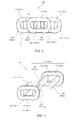
- FIG. 1 illustrates a principal portion of a chain-type continuously variable transmission (CVT) 10.
- the chain-type CVT 10 includes two pulleys 12 and 14, and a chain 16 which is wrapped around these pulleys.
- One of the two pulleys will be referred to as an input pulley 12 and the other will be referred to as an output pulley 14.
- the input pulley 12 includes a fixed sheave 20 which is fixed to an input shaft 18, and a movable sheave 22 which is movable on the input shaft 18 by sliding along the input shaft 18.
- a surface of the fixed sheave 20 and a surface of the movable sheave 22 that are opposite each other have a shape of a substantially lateral surface of a cone. As illustrated, these substantially cone lateral surfaces are surfaces formed so as to expand with respect to the lateral surface of a cone. These surfaces will be referred to as substantially conical surfaces 24 and 26. These substantially conical surfaces 24 and 26 together form a V-shaped groove, in which the chain 16 is disposed such that side surfaces of the chain 16 are clamped between the substantially conical surfaces 24 and 26.
- the output pulley 14 includes a fixed sheave 30 which is fixed to an output shaft 28, and a movable sheave 32 which is movable on the output shaft 28 by sliding along the output shaft 28.
- a surface of the fixed sheave 30 and a surface of the movable sheave 32 that are opposite each other have a shape of a substantially lateral surface of a cone. As illustrated, these substantially cone lateral surfaces are surfaces formed so as to expand with respect to the lateral surface of a cone. These surfaces will be referred to as substantially conical surfaces 34 and 36. These substantially conical surfaces 34 and 36 together form a V-shaped groove, in which the chain 16 is disposed such that side surfaces of the chain 16 are clamped between the substantially conical surfaces 34 and 36.
- the arrangement of the fixed sheave and the movable sheave is reversed between the input pulley 12 and the output pulley 14.
- the movable sheave 22 is located on the right side in the input pulley 12
- the movable sheave 32 is located on the left side in the output pulley 14.
- the groove width increases, so that the chain 16 moves to a deeper position in the groove to thereby decrease the wrapping radius.
- the groove width decreases, so that the chain 16 moves to a shallow depth position in the groove to thereby increase the wrapping radius.
- the chain 16 is prevented from being loosened.
- FIGs. 2 to 4 illustrate details of the chain 16.
- the direction along the extending direction of the chain 16 will be referred to as a circumferential direction
- the direction which is orthogonal to the circumferential direction and is parallel to the input shaft 18 and the output shaft 28 will be referred to a width direction
- the direction which is orthogonal to the circumferential direction and the width direction will be referred to as a thickness direction.
- FIG. 2 is a view illustrating a portion of the chain 16 seen from the width direction
- FIG. 3 is a view illustrating a part of the chain 16 which is extracted and decomposed
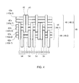
- FIG. 4 is a view illustrating a portion of the chain 16 seen from the outer peripheral side in the thickness direction.
- the chain 16 is formed of a combination of plate-shape links 40 each having an opening 38 and rod-shape pins 42a and 42b.
- the individual links 40 have the same shape, including the same thickness, and the rod-shape pins 42a have the same shape and the rod-shape pins 42b have the same shape.
- the links 40 are arranged in a predetermined pattern (see FIG. 4 ) in the width direction, and two pins 42a and 42b extend through the opening of each link at respective ends of the link.
- FIG. 3 illustrates two chain elements 44-1 and 44-2.
- the suffix "-1", “-2”, “-3” ... is used to discriminate a chain element, and links and pins included in the chain element, from those of other chain elements.
- the chain element 44-1 is composed of a plurality of links 40-1 and the two pins 42a-1 and 42b-1 extending through the links 40-1.
- the two pins 42a-1 and 42b-1 are press fitted into or fixed and bonded to the opening 38-1 at the respective ends of the link 40-1.
- the chain element 44-2 is composed of a plurality of links 40-2 and the two pins 42a-2 and 42b-2 extending therethrough.
- the whole links 40 included in one chain element will be referred to as a link unit 46.
- the suffix "-1", “-2", “-3” ... described above is also used for the link unit 46 when it is necessary to discriminate the chain elements included in the link unit 46.
- the chain elements 44-1 and 44-2 which are adjacent to each other can be interconnected by allowing the pin 42 of one chain element to pass through the opening 38 in the other chain element and vice versa.
- the pin 42b-1 of the chain element 44-1 on the left side of the drawing is placed within the opening 38-2 so as to be positioned on the right side of the pin 42a-2 of the chain element 44-2 on the right side.
- the pin 42a-2 of the chain element 44-2 on the right side is placed within the opening 38-1 so as to be positioned on the left side of the pin 42b-1 of the chain element 44-1 on the left side.
- the arrangement pattern of the links 40 within the link unit 46 is the same every three link units in the circumferential direction.
- a set of three chain elements 44 having different link arrangement patterns will be referred to as an element module 48.
- the chain 16 can be regarded as an arrangement of the element modules 48 having the same link arrangement pattern in the circumferential direction.
- one element module 48 includes twenty-five links 40, and the numbers of links of the three link units 46 included in the one element module 48 are 9, 8, and 8, respectively.
- FIG. 4 is a view illustrating one example arrangement pattern of the links 40, and illustrates half the width of the chain 16, with the other half having a symmetrical pattern.
- Each link 40 belongs to one row, which will be referred to as the first row, the second row, and so on, from the left side of the drawing. (In FIG. 4 , the row number is indicated as an encircled number.) As the thickness of the link 40 is uniform, the rows are arranged at an equal pitch.
- the link 40 in the first row is included in a first link unit 46-1
- the link 40 in the second row is included in a second link unit 46-2
- the link 40 in the third row is included in a third link unit 46-3.
- the bending amount of the pins 42a and 42b differs from pin to pin, which makes the stress generated in each link also differ.
- the pins 42a and 42b are pinched between the pulleys 12 and 14 a friction force in the circumferential direction is generated between the end surface of the pin and the conical surface 24, 26, 34, 36, causing the pins 42a and 42b to bend.
- the stress generated in the link 40 is increased or decreased with a period of one rotation of the chain 16.
- the quantity of this increases and decreases; that is, an amplitude, of the stress affects the durability of the chain 16.
- this feature can be utilized to reduce the amplitude of stress generated in the link.
- FIG. 5 illustrates a stress distribution calculation model.
- Two adjacent pins e.g. 42a-2, 42b-1 are approximated by a single beam 50, and the link 40 is approximated by a spring 52.
- the location of the spring indicated by a solid line in FIG. 5 corresponds to a location where the link 40 is actually disposed.
- the beams 50 are arranged at a pitch Lp, the value of which increases and decreases by ⁇ due to a tension or the like. Further, a force acting between the beam 50 and the spring 52 is indicated as f, and bending of the beam 50 caused by this force f is indicated as ⁇ .
- the links in the two outermost rows of the chain are included in the same link unit, the links in the following two rows are included in the same link unit which differs from the link unit in which the outermost links are included, and, on the further inner side, the links in three or more rows are disposed in the same link unit other than the above-described two link units.
- one element module 48 includes twenty-five links 40, and the three link units include nine links 40, eight links 40, and eight links 40, respectively.
- a width-direction unit 54 is defined for every three rows from the right and left ends. More specifically, the links 40 in the first to third rows define one width-direction unit, the links 40 in the fourth to sixth rows define another width-direction unit, and so on. The link in the thirteenth row at the center is not included in any width-direction unit.
- the three links that belong to one width-direction unit 54 are included in different link units 46. For example, referring to FIG.
- the link 40 in the first row is included in the first link unit 46-1
- the link 40 in the second row is included in the second link unit 46-2
- the link 40 in the third row is included in the third link unit 46-3. This is because it is intended that the links as a whole are arranged substantially evenly in the width direction within the link unit.
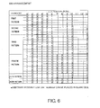
- FIG. 6 shows specific link arrangement patterns, and indicates the row (link position) of the link and the corresponding link unit 46.
- “1" indicates the first link unit 46-1
- "2" indicates the second link unit 46-2
- "3" indicates the third link unit 46-3.
- a blank cell indicates that the link 40 in that row can be included in an arbitrary link unit so long as the condition that three links in one width-direction unit 54 are included in respectively different link units is satisfied.
- the position at which the stress amplitude of the link 40 is maximum is near the end portion of a range where the pin is in contact with the link (the location where the stress is converged), as indicated by "A" in FIG. 2 .
- Each arrangement pattern of the links will be evaluated with reference to the stress in this portion.
- the links in the first row and the sixth row are included in the same link unit
- the links in the second row and the fifth row are included in the same link unit
- the links in the ninth row and the tenth row are included in a link unit other than the link unit in which the links in the second and the fifth rows are included.
- the links in the second row and the fifth row are supposed to be included in the second or third link unit that are units other than the first link unit.
- the cases in which the links in the second row and the fifth row are included in the second link unit are indicated in the upper two levels and the cases in which the links in the second row and the fifth row are included in the third link unit are indicated in the lower two levels in the first pattern.
- the link unit corresponding to the third row is automatically determined by determining the link units corresponding to the first and second rows, and corresponds to the third link unit in the upper two levels of pattern 1 and the second link unit in the lower two levels of the same.
- the links 40 in the ninth row and the tenth row are included in the same link unit which is different from the link unit corresponding to the second and fifth rows. Therefore, in the case of the upper two levels, the links in the ninth row and the tenth row are included in the first link unit (see the first level in FIG. 6 ) or the third link unit (see the second level in FIG. 6 ) other than the second link unit in which the links in the second and fifth rows are included. If the links in the second and fifth rows are included in the third link unit (the lower two levels of pattern 1 in FIG. 6 ), the links in the ninth row and the tenth row are included in the first link unit (see the third level in FIG. 6 ) or the second link unit (see the fourth level in FIG. 6 ).
- FIG. 7 corresponds to the first pattern at the first level in FIG. 6 ;
- FIG. 8 corresponds to the first pattern at the second level in FIG. 6 ;
- FIG. 9 corresponds to the third level; and
- FIG. 10 corresponds to the fourth level.
- the link indicated by alternate long and short dashed lines can be placed at a desired position so long as the condition that the three links in one width-direction unit are included in different link units is satisfied.
- the links in the first row and the sixth row are included in the same link unit; the links in the second row, the fifth row, the ninth row, and the tenth row are included in the same link unit; and the link in the thirteenth row is included in a link unit other than the link unit in which the links in the second row, the fifth row, the ninth row, and the tenth row are included.
- the procedure of arrangement of the links and drawings specifically illustrating the link arrangement patterns will be omitted. These can be easily understood with reference to the description and the drawings related to the first pattern.
- the links in the first row and the sixth row are included in the same link unit; the links in the second row and the fifth row are included in the same link unit; the link in the ninth row is included in a link unit other than the link unit in which the links in the second and the fifth rows are included; and the links in the tenth row and the thirteenth row are included in the same link unit other than the link unit in which the link in the ninth row is included.
- the links in the first row and the sixth row are included in the same link unit; the links in the second row and the fifth row are included in the same link unit; the link in the ninth row is included in a link unit other than the link unit in which the links in the second and the fifth rows are included; the links in the ninth row, the tenth row, and the thirteenth row are included in different link units; and the links in the seventh row and the thirteenth row are included in the same link unit.
- the link unit corresponding to the eighth row is automatically determined by determining the link units corresponding to the seventh and ninth rows.
- the links in the first row and the sixth row are included in the same link unit; the links in the second row, the fourth row, and the thirteenth row are included in the same link unit; and the links in the third row, the fifth row, the seventh row, and the tenth row are included in the same link unit.
- the links in the first row, the fifth row, and the ninth row are included in the same link unit; the links in the second row, the sixth row, the seventh row, and the tenth row are included in the same link unit; and the links in the third row, the fourth row, and the thirteenth row are included in the same link unit.
- the link unit corresponding to the eighth row is automatically determined by determining the link units corresponding to the seventh and ninth rows.
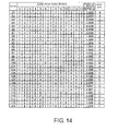
- FIG. 11 illustrates a relationship between the link arrangement pattern and the maximum stress amplitude of the link.
- the arrangement patterns indicated along the horizontal axis include all the arrangement patterns that satisfy the condition that three links in one width-direction unit 54 are included in different link units 46. Along the horizontal axis, these arrangement patterns are arranged in ascending order of maximum stress amplitude.
- the maximum stress amplitude of the link is represented by a ratio with respect to the smallest value concerning the arrangement patterns of Patent Document 1.
- the arrangement pattern for which the maximum stress value is the greatest ranks number 195 in ascending order of the stress amplitude As the total number of the arrangement patterns is 1296, it can be understood that the above-described arrangement pattern is rated as being in the top 15%.
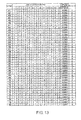
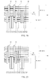
- FIGs. 12 to 15 indicate all the patterns corresponding to the sixth arrangement patterns described above in ascending order of the maximum stress amplitude of the link.
- the maximum stress amplitude of the link in the third row is recorded in the first and second arrangement patterns
- the maximum stress amplitude of the link in the first row is recorded in the third to sixth arrangement patterns.
- one element module 48 includes twenty-four links 40, and the numbers of links in three link units are 8, 8, and 8, respectively. Further, in one element module 48, a width-direction unit 54 is defined for every three rows from the right end and the left end. Specifically, the links 40 in the first to third rows define one width-direction unit 54, the links 40 in the fourth to sixth rows define another width-direction unit 54, and so on. The three links within one width-direction unit 54 are included in different link units 46.
- FIG. 16 indicates specific link arrangement patterns, and shows the row (link position) of the link and the corresponding link unit 46 in which the link is included.
- “1" indicates the first link unit 46-1
- "2" indicates the second link unit 46-2
- "3" indicates the third link unit 46-3.
- a blank cell indicates that the link 40 in that row can be included in an arbitrary link unit so long as the condition that three links in one width-direction unit 54 are included in different link units is satisfied.
- the position at which the stress amplitude of the link 40 is maximum is near the inner end portion of the chain in a range where the pin is in contact with the link (the location where the stress is converged), as indicated by "A” in FIG. 2 .
- Each arrangement pattern of the links will be evaluated with reference to the stress in this portion.
- the links in the first row and the sixth row are included in the same link unit
- the links in the second row and the fifth row are included in the same link unit
- the links in the ninth row and the tenth row are included in the same link unit other than the link unit in which the links in the second and the fifth rows are included.
- the links in the first row and the sixth row are included in the first link unit
- the links in the second row and the fifth row are supposed to be included in the second or third link unit that are link units other than the first link unit.
- the cases in which the links in the second row and the fifth row are included in the second link unit are indicated in the upper two levels and the cases in which the links in the second row and the fifth row are included in the third link unit are indicated in the lower two levels in the seventh pattern.
- the link unit corresponding to the third row is automatically determined by determining the link units corresponding to the first and second rows, and corresponds to the third link unit in the upper two levels and the second link unit in the lower two levels.
- the links 40 in the ninth row and the tenth row are included in the same link unit which is different from the link unit corresponding to the second and fifth rows. Therefore, in the case of the upper two levels, the links in the ninth row and the tenth row are included in the first link unit (see the first level in FIG. 16 ) or the third link unit (see the second level in FIG. 16 ) other than the second link unit in which the links in the second and fifth rows are included. If the links in the second and fifth rows are included in the third link unit (the lower two levels of the seventh pattern in FIG. 16 ), the links in the ninth row and the tenth row are included in the first link unit (see the third level of the seventh pattern in FIG. 16 ) or the second link unit (see the fourth level of the seventh pattern in FIG. 16 ).
- FIG. 17 corresponds to the seventh pattern at the first level in FIG. 16 ;
- FIG. 18 corresponds to the seventh pattern at the second level in FIG. 16 ;
- FIG. 19 corresponds to the third level; and
- FIG. 20 corresponds to the fourth level.
- the link indicated by alternate long and short dashed lines can be placed at a desired position so long as the condition that the three links in one width-direction unit are included in different link units is satisfied.
- the links in the first row and the sixth row are included in the same link unit; the links in the second row and the fifth row are included in the same link unit; the links in the third row, the fourth row, and the ninth row are included in the same link unit; and the links in the ninth row, the tenth row, and the twelfth row are included in different link units.
- the procedure of arrangement of the links and specific arrangement patterns which can be easily understood with reference to the description and the drawings related to the seventh pattern, will be omitted.
- FIG. 21 illustrates a relationship between the link arrangement pattern and the maximum stress amplitude of the link.
- the arrangement patterns indicated along the horizontal axis include all the arrangement patterns that satisfy the condition that three links in one width-direction unit 54 are included in respectively different link units 46. Along the horizontal axis, these arrangement patterns are arranged in ascending order of maximum stress amplitude.
- the maximum stress amplitude of the link is represented by a ratio with respect to the smallest value concerning the arrangement patterns of Patent Document 1.
- the arrangement pattern for which the maximum stress value is the greatest ranks number 24 in the ascending order of stress amplitude As the total number of the arrangement patterns is 432, it can be understood that the above-described arrangement pattern is rated as being in the top 5.6%.
- FIG. 22 indicates all the patterns corresponding to the two arrangement patterns described above in ascending order of maximum stress amplitude of the link.
- the maximum stress amplitude of the link in the third row is recorded in the first to fourth arrangement patterns
- the maximum stress amplitude of the link in the first row is recorded in the fifth and sixth arrangement patterns.
Landscapes
- Engineering & Computer Science (AREA)
- General Engineering & Computer Science (AREA)
- Mechanical Engineering (AREA)
- Transmissions By Endless Flexible Members (AREA)
Applications Claiming Priority (1)
| Application Number | Priority Date | Filing Date | Title |
|---|---|---|---|
| JP2011239441A JP5851799B2 (ja) | 2011-10-31 | 2011-10-31 | 無段変速機のチェーン |
Publications (3)
| Publication Number | Publication Date |
|---|---|
| EP2587091A2 true EP2587091A2 (de) | 2013-05-01 |
| EP2587091A3 EP2587091A3 (de) | 2013-09-18 |
| EP2587091B1 EP2587091B1 (de) | 2016-12-07 |
Family
ID=47143609
Family Applications (1)
| Application Number | Title | Priority Date | Filing Date |
|---|---|---|---|
| EP12190514.5A Not-in-force EP2587091B1 (de) | 2011-10-31 | 2012-10-30 | Kette für ein durchgehendes variables Getriebe |
Country Status (4)
| Country | Link |
|---|---|
| US (2) | US9303724B2 (de) |
| EP (1) | EP2587091B1 (de) |
| JP (1) | JP5851799B2 (de) |
| CN (1) | CN103089946B (de) |
Cited By (1)
| Publication number | Priority date | Publication date | Assignee | Title |
|---|---|---|---|---|
| CN116324217A (zh) * | 2020-11-12 | 2023-06-23 | 舍弗勒技术股份两合公司 | 平环链和锥形盘带传动装置 |
Families Citing this family (8)
| Publication number | Priority date | Publication date | Assignee | Title |
|---|---|---|---|---|
| JP5851799B2 (ja) | 2011-10-31 | 2016-02-03 | 株式会社豊田中央研究所 | 無段変速機のチェーン |
| JP6298736B2 (ja) * | 2014-08-08 | 2018-03-20 | 株式会社豊田中央研究所 | 無段変速機及び無段変速機を設計する方法 |
| US10619705B2 (en) * | 2015-05-11 | 2020-04-14 | Schaeffler Technologies AG & Co. KG | Belt means and system for constructing a belt means |
| CN105134877A (zh) * | 2015-07-22 | 2015-12-09 | 杭州东华链条集团有限公司 | 一种cvt静音链及变速箱 |
| DE102020129928B4 (de) | 2020-11-12 | 2022-10-13 | Schaeffler Technologies AG & Co. KG | Laschenkette und Kegelscheibenumschlingungsgetriebe |
| DE102020129934B4 (de) | 2020-11-12 | 2022-12-22 | Schaeffler Technologies AG & Co. KG | Laschenkette und Kegelscheibenumschlingungsgetriebe |
| DE102020129936B4 (de) | 2020-11-12 | 2022-10-13 | Schaeffler Technologies AG & Co. KG | Laschenkette und Kegelscheibenumschlingungsgetriebe |
| DE102020130154B4 (de) | 2020-11-16 | 2022-10-06 | Schaeffler Technologies AG & Co. KG | Laschenkette und Kegelscheibenumschlingungsgetriebe |
Citations (1)
| Publication number | Priority date | Publication date | Assignee | Title |
|---|---|---|---|---|
| JP4372551B2 (ja) | 2001-12-14 | 2009-11-25 | ルーク ラメレン ウント クツプルングスバウ ベタイリグングス コマンディートゲゼルシャフト | 特に伝動装置の2つの円錐形プーリ対の間の力伝達のための巻き掛け手段を備えた伝動装置 |
Family Cites Families (42)
| Publication number | Priority date | Publication date | Assignee | Title |
|---|---|---|---|---|
| DE3027834C2 (de) * | 1980-07-23 | 1982-11-04 | P.I.V. Antrieb Werner Reimers GmbH & Co KG, 6380 Bad Homburg | Laschenkette für stufenlos verstellbare Kegelscheibengetriebe |
| DE3826809C1 (de) * | 1988-08-06 | 1989-08-24 | P.I.V. Antrieb Werner Reimers Gmbh & Co Kg, 6380 Bad Homburg, De | |
| NL1000294C2 (nl) * | 1995-05-03 | 1996-11-05 | Gear Chain Ind Bv | Transmissieketting voor een kegeldrijfwerk. |
| DE19855582A1 (de) * | 1997-12-05 | 1999-06-10 | Luk Getriebe Systeme Gmbh | Laschenkette |
| US6135908A (en) * | 1998-05-20 | 2000-10-24 | Luk Getriebe-Systeme Gmbh | Enwrapping device |
| DE19934935B4 (de) * | 1998-07-30 | 2015-08-06 | Schaeffler Technologies AG & Co. KG | Umschlingungsmittel |
| DE19960914A1 (de) * | 1998-12-28 | 2000-06-29 | Luk Getriebe Systeme Gmbh | Umschlingungsmittel |
| DE10036258B4 (de) * | 1999-09-09 | 2013-02-28 | Schaeffler Technologies AG & Co. KG | Laschenkette |
| DE10047979B4 (de) | 1999-10-13 | 2013-05-16 | Schaeffler Technologies AG & Co. KG | Kette |
| DE10052473A1 (de) * | 1999-11-19 | 2001-05-23 | Luk Lamellen & Kupplungsbau | Laschenkette |
| DE10139123A1 (de) * | 2000-09-06 | 2002-03-14 | Luk Lamellen & Kupplungsbau | Laschenkette |
| JP2002174303A (ja) | 2000-11-30 | 2002-06-21 | Luk Lamellen & Kupplungsbau Beteiligungs Kg | リンクプレートチェーン |
| DE102004012400B4 (de) * | 2003-03-21 | 2016-01-07 | Schaeffler Technologies AG & Co. KG | Laschenkette für ein Kegelscheibenumschlingungsgetriebe sowie Wiegedruckstück |
| JPWO2005038295A1 (ja) | 2003-10-17 | 2007-01-11 | 株式会社ジェイテクト | 動力伝達チェーン及びそれを用いた動力伝達装置 |
| CN100425867C (zh) * | 2003-10-17 | 2008-10-15 | 株式会社捷太格特 | 动力传输链及采用了该链的动力传输装置 |
| JPWO2005050055A1 (ja) * | 2003-11-10 | 2007-06-07 | 株式会社ジェイテクト | 動力伝達チェーンおよび動力伝達装置ならびにその製造方法 |
| US20070191166A1 (en) | 2004-03-05 | 2007-08-16 | Jtekt Corporation | Power transmission chain and power transmission device |
| JP4941698B2 (ja) * | 2005-02-04 | 2012-05-30 | 株式会社ジェイテクト | 動力伝達チェーンおよびこれを備える動力伝達装置 |
| JP2007051711A (ja) * | 2005-08-18 | 2007-03-01 | Jtekt Corp | 動力伝達チェーンおよびこれを備える動力伝達装置 |
| US7686722B2 (en) * | 2005-10-01 | 2010-03-30 | Luk Lamellen Und Kupplungsbau Beteiligungs Kg | Plate-link chain for a continuously variable transmission |
| DE112006002461A5 (de) | 2005-10-06 | 2008-06-19 | Luk Lamellen Und Kupplungsbau Beteiligungs Kg | Kettenlasche, diese beinhaltende Kette, sowie damit gebildeter Kettentrieb und damit ausgerüstetes Fahrzeug |
| JP4853017B2 (ja) * | 2005-12-26 | 2012-01-11 | 株式会社ジェイテクト | 動力伝達チェーンおよびその製造方法ならびに動力伝達装置 |
| DE602007007681D1 (de) * | 2006-03-24 | 2010-08-26 | Jtekt Corp | Kraftübertragungskette und Kraftübertragungssystem |
| JP4923799B2 (ja) * | 2006-07-13 | 2012-04-25 | 株式会社ジェイテクト | 動力伝達チェーンおよび動力伝達装置 |
| JP5218804B2 (ja) * | 2006-09-15 | 2013-06-26 | 株式会社ジェイテクト | 動力伝達チェーンおよびこれを備える動力伝達装置 |
| EP2085643B1 (de) * | 2006-10-31 | 2018-06-27 | JTEKT Corporation | Verfahren und vorrichtung zum strecken einer kraftübertragungskette |
| WO2008069319A1 (ja) * | 2006-12-08 | 2008-06-12 | Jtekt Corporation | 動力伝達チェーンおよび動力伝達装置 |
| US20100035713A1 (en) * | 2006-12-08 | 2010-02-11 | Yoshihisa Miura | Power transmission chain and power transmission device |
| WO2008071145A1 (de) * | 2006-12-15 | 2008-06-19 | Luk Lamellen Und Kupplungsbau Beteiligungs Kg | Laschenkette |
| JP2008267578A (ja) * | 2007-04-25 | 2008-11-06 | Jtekt Corp | 動力伝達チェーンおよび動力伝達装置 |
| JP5211606B2 (ja) | 2007-09-25 | 2013-06-12 | 株式会社ジェイテクト | 動力伝達チェーンおよび動力伝達装置 |
| CN101809316B (zh) * | 2007-09-27 | 2013-03-27 | 株式会社捷太格特 | 动力传递链条及动力传递装置 |
| JP4893561B2 (ja) * | 2007-09-27 | 2012-03-07 | 株式会社ジェイテクト | 動力伝達チェーンおよび動力伝達装置 |
| JP4997537B2 (ja) * | 2007-10-22 | 2012-08-08 | 株式会社ジェイテクト | 動力伝達チェーンおよび動力伝達装置 |
| JP5152575B2 (ja) * | 2008-04-16 | 2013-02-27 | 株式会社ジェイテクト | 動力伝達チェーンおよびこれを備える動力伝達装置 |
| JP2011524501A (ja) * | 2008-06-19 | 2011-09-01 | シェフラー テクノロジーズ ゲゼルシャフト ミット ベシュレンクテル ハフツング ウント コンパニー コマンディートゲゼルシャフト | リンクプレートチェーン |
| JP5526968B2 (ja) * | 2009-08-07 | 2014-06-18 | 株式会社ジェイテクト | 動力伝達装置 |
| JP5639135B2 (ja) * | 2011-10-31 | 2014-12-10 | 株式会社豊田中央研究所 | チェーン式無段変速機 |
| JP5851799B2 (ja) * | 2011-10-31 | 2016-02-03 | 株式会社豊田中央研究所 | 無段変速機のチェーン |
| JP5951427B2 (ja) * | 2012-08-10 | 2016-07-13 | 株式会社豊田中央研究所 | 無段変速機のチェーン |
| JP5951418B2 (ja) * | 2012-09-06 | 2016-07-13 | 株式会社豊田中央研究所 | 無段変速機のチェーン |
| JP6190743B2 (ja) * | 2014-03-24 | 2017-08-30 | 本田技研工業株式会社 | 無段変速機のリンクプレートチェーン |
-
2011
- 2011-10-31 JP JP2011239441A patent/JP5851799B2/ja not_active Expired - Fee Related
-
2012
- 2012-10-29 CN CN201210421068.8A patent/CN103089946B/zh not_active Expired - Fee Related
- 2012-10-30 EP EP12190514.5A patent/EP2587091B1/de not_active Not-in-force
- 2012-10-30 US US13/664,167 patent/US9303724B2/en not_active Expired - Fee Related
-
2016
- 2016-02-25 US US15/053,598 patent/US9464688B2/en not_active Expired - Fee Related
Patent Citations (1)
| Publication number | Priority date | Publication date | Assignee | Title |
|---|---|---|---|---|
| JP4372551B2 (ja) | 2001-12-14 | 2009-11-25 | ルーク ラメレン ウント クツプルングスバウ ベタイリグングス コマンディートゲゼルシャフト | 特に伝動装置の2つの円錐形プーリ対の間の力伝達のための巻き掛け手段を備えた伝動装置 |
Cited By (1)
| Publication number | Priority date | Publication date | Assignee | Title |
|---|---|---|---|---|
| CN116324217A (zh) * | 2020-11-12 | 2023-06-23 | 舍弗勒技术股份两合公司 | 平环链和锥形盘带传动装置 |
Also Published As
| Publication number | Publication date |
|---|---|
| JP2013096493A (ja) | 2013-05-20 |
| CN103089946B (zh) | 2016-08-03 |
| US20130109521A1 (en) | 2013-05-02 |
| US20160178032A1 (en) | 2016-06-23 |
| US9303724B2 (en) | 2016-04-05 |
| EP2587091A3 (de) | 2013-09-18 |
| CN103089946A (zh) | 2013-05-08 |
| JP5851799B2 (ja) | 2016-02-03 |
| EP2587091B1 (de) | 2016-12-07 |
| US9464688B2 (en) | 2016-10-11 |
Similar Documents
| Publication | Publication Date | Title |
|---|---|---|
| EP2587091B1 (de) | Kette für ein durchgehendes variables Getriebe | |
| US7204775B2 (en) | Plate-link chain for a continuously variable transmission | |
| KR20090081319A (ko) | 사일런트 체인 | |
| US7617668B2 (en) | Method of producing power transmission chain and press-fitting apparatus used in said method | |
| US9316287B2 (en) | Chain for continuously variable transmission | |
| US9377081B2 (en) | Chain for continuously variable transmission | |
| EP2587090A2 (de) | Kettenartiges durchgehendes variables Getriebe | |
| US9199302B2 (en) | Assembly jig for pins for power transmission chain | |
| US7470204B2 (en) | Transmission with belt elements, especially for the transmission of force between two pairs of conical disks of the transmission | |
| JP2015503716A (ja) | 互いに異なる幅を有する2つのタイプの横方向部材を備えた、無段変速機に用いられる駆動ベルト | |
| JP5614223B2 (ja) | 無段変速伝動機構 | |
| US20080004146A1 (en) | Power transmission chain, and power transmission device having the same | |
| JP4893561B2 (ja) | 動力伝達チェーンおよび動力伝達装置 | |
| WO2014023336A1 (en) | Transmission chain with rollers or bushings with inner link with convex back and with smaller outer link with a peanut shape | |
| JP2009257487A (ja) | 動力伝達チェーンおよび動力伝達装置 | |
| JP6812890B2 (ja) | 無段変速機のチェーン | |
| JP2016183689A (ja) | 無段変速機のチェーン | |
| JP5659613B2 (ja) | 動力伝達チェーンの製造方法 | |
| JP6221045B2 (ja) | 無段変速機用金属ベルト | |
| JP2009047297A (ja) | 動力伝達チェーンおよび動力伝達装置 | |
| JP2018136004A (ja) | 動力伝達用チェーン | |
| JP2010038311A (ja) | 動力伝達チェーンおよび動力伝達装置 | |
| JP2010025130A (ja) | 動力伝達チェーンおよび動力伝達装置 |
Legal Events
| Date | Code | Title | Description |
|---|---|---|---|
| PUAI | Public reference made under article 153(3) epc to a published international application that has entered the european phase |
Free format text: ORIGINAL CODE: 0009012 |
|
| AK | Designated contracting states |
Kind code of ref document: A2 Designated state(s): AL AT BE BG CH CY CZ DE DK EE ES FI FR GB GR HR HU IE IS IT LI LT LU LV MC MK MT NL NO PL PT RO RS SE SI SK SM TR |
|
| AX | Request for extension of the european patent |
Extension state: BA ME |
|
| PUAL | Search report despatched |
Free format text: ORIGINAL CODE: 0009013 |
|
| AK | Designated contracting states |
Kind code of ref document: A3 Designated state(s): AL AT BE BG CH CY CZ DE DK EE ES FI FR GB GR HR HU IE IS IT LI LT LU LV MC MK MT NL NO PL PT RO RS SE SI SK SM TR |
|
| AX | Request for extension of the european patent |
Extension state: BA ME |
|
| RIC1 | Information provided on ipc code assigned before grant |
Ipc: F16G 5/18 20060101AFI20130812BHEP |
|
| 17P | Request for examination filed |
Effective date: 20140318 |
|
| RBV | Designated contracting states (corrected) |
Designated state(s): AL AT BE BG CH CY CZ DE DK EE ES FI FR GB GR HR HU IE IS IT LI LT LU LV MC MK MT NL NO PL PT RO RS SE SI SK SM TR |
|
| GRAP | Despatch of communication of intention to grant a patent |
Free format text: ORIGINAL CODE: EPIDOSNIGR1 |
|
| INTG | Intention to grant announced |
Effective date: 20160518 |
|
| GRAS | Grant fee paid |
Free format text: ORIGINAL CODE: EPIDOSNIGR3 |
|
| GRAA | (expected) grant |
Free format text: ORIGINAL CODE: 0009210 |
|
| RIN1 | Information on inventor provided before grant (corrected) |
Inventor name: MORI, KEISUKE Inventor name: NAKAZAWA, TERUHIKO Inventor name: YAMANE, SHINJI Inventor name: NAGASAWA, YUJI Inventor name: TARUTANI, ICHIRO |
|
| AK | Designated contracting states |
Kind code of ref document: B1 Designated state(s): AL AT BE BG CH CY CZ DE DK EE ES FI FR GB GR HR HU IE IS IT LI LT LU LV MC MK MT NL NO PL PT RO RS SE SI SK SM TR |
|
| REG | Reference to a national code |
Ref country code: GB Ref legal event code: FG4D |
|
| REG | Reference to a national code |
Ref country code: CH Ref legal event code: EP Ref country code: AT Ref legal event code: REF Ref document number: 852035 Country of ref document: AT Kind code of ref document: T Effective date: 20161215 |
|
| REG | Reference to a national code |
Ref country code: IE Ref legal event code: FG4D |
|
| REG | Reference to a national code |
Ref country code: DE Ref legal event code: R096 Ref document number: 602012026255 Country of ref document: DE |
|
| PG25 | Lapsed in a contracting state [announced via postgrant information from national office to epo] |
Ref country code: LV Free format text: LAPSE BECAUSE OF FAILURE TO SUBMIT A TRANSLATION OF THE DESCRIPTION OR TO PAY THE FEE WITHIN THE PRESCRIBED TIME-LIMIT Effective date: 20161207 |
|
| REG | Reference to a national code |
Ref country code: LT Ref legal event code: MG4D |
|
| REG | Reference to a national code |
Ref country code: NL Ref legal event code: MP Effective date: 20161207 |
|
| PG25 | Lapsed in a contracting state [announced via postgrant information from national office to epo] |
Ref country code: GR Free format text: LAPSE BECAUSE OF FAILURE TO SUBMIT A TRANSLATION OF THE DESCRIPTION OR TO PAY THE FEE WITHIN THE PRESCRIBED TIME-LIMIT Effective date: 20170308 Ref country code: LT Free format text: LAPSE BECAUSE OF FAILURE TO SUBMIT A TRANSLATION OF THE DESCRIPTION OR TO PAY THE FEE WITHIN THE PRESCRIBED TIME-LIMIT Effective date: 20161207 Ref country code: NO Free format text: LAPSE BECAUSE OF FAILURE TO SUBMIT A TRANSLATION OF THE DESCRIPTION OR TO PAY THE FEE WITHIN THE PRESCRIBED TIME-LIMIT Effective date: 20170307 Ref country code: SE Free format text: LAPSE BECAUSE OF FAILURE TO SUBMIT A TRANSLATION OF THE DESCRIPTION OR TO PAY THE FEE WITHIN THE PRESCRIBED TIME-LIMIT Effective date: 20161207 |
|
| REG | Reference to a national code |
Ref country code: AT Ref legal event code: MK05 Ref document number: 852035 Country of ref document: AT Kind code of ref document: T Effective date: 20161207 |
|
| PG25 | Lapsed in a contracting state [announced via postgrant information from national office to epo] |
Ref country code: FI Free format text: LAPSE BECAUSE OF FAILURE TO SUBMIT A TRANSLATION OF THE DESCRIPTION OR TO PAY THE FEE WITHIN THE PRESCRIBED TIME-LIMIT Effective date: 20161207 Ref country code: ES Free format text: LAPSE BECAUSE OF FAILURE TO SUBMIT A TRANSLATION OF THE DESCRIPTION OR TO PAY THE FEE WITHIN THE PRESCRIBED TIME-LIMIT Effective date: 20161207 Ref country code: RS Free format text: LAPSE BECAUSE OF FAILURE TO SUBMIT A TRANSLATION OF THE DESCRIPTION OR TO PAY THE FEE WITHIN THE PRESCRIBED TIME-LIMIT Effective date: 20161207 Ref country code: HR Free format text: LAPSE BECAUSE OF FAILURE TO SUBMIT A TRANSLATION OF THE DESCRIPTION OR TO PAY THE FEE WITHIN THE PRESCRIBED TIME-LIMIT Effective date: 20161207 |
|
| PG25 | Lapsed in a contracting state [announced via postgrant information from national office to epo] |
Ref country code: NL Free format text: LAPSE BECAUSE OF FAILURE TO SUBMIT A TRANSLATION OF THE DESCRIPTION OR TO PAY THE FEE WITHIN THE PRESCRIBED TIME-LIMIT Effective date: 20161207 |
|
| PG25 | Lapsed in a contracting state [announced via postgrant information from national office to epo] |
Ref country code: RO Free format text: LAPSE BECAUSE OF FAILURE TO SUBMIT A TRANSLATION OF THE DESCRIPTION OR TO PAY THE FEE WITHIN THE PRESCRIBED TIME-LIMIT Effective date: 20161207 Ref country code: SK Free format text: LAPSE BECAUSE OF FAILURE TO SUBMIT A TRANSLATION OF THE DESCRIPTION OR TO PAY THE FEE WITHIN THE PRESCRIBED TIME-LIMIT Effective date: 20161207 Ref country code: IS Free format text: LAPSE BECAUSE OF FAILURE TO SUBMIT A TRANSLATION OF THE DESCRIPTION OR TO PAY THE FEE WITHIN THE PRESCRIBED TIME-LIMIT Effective date: 20170407 Ref country code: CZ Free format text: LAPSE BECAUSE OF FAILURE TO SUBMIT A TRANSLATION OF THE DESCRIPTION OR TO PAY THE FEE WITHIN THE PRESCRIBED TIME-LIMIT Effective date: 20161207 Ref country code: EE Free format text: LAPSE BECAUSE OF FAILURE TO SUBMIT A TRANSLATION OF THE DESCRIPTION OR TO PAY THE FEE WITHIN THE PRESCRIBED TIME-LIMIT Effective date: 20161207 |
|
| PG25 | Lapsed in a contracting state [announced via postgrant information from national office to epo] |
Ref country code: SM Free format text: LAPSE BECAUSE OF FAILURE TO SUBMIT A TRANSLATION OF THE DESCRIPTION OR TO PAY THE FEE WITHIN THE PRESCRIBED TIME-LIMIT Effective date: 20161207 Ref country code: AT Free format text: LAPSE BECAUSE OF FAILURE TO SUBMIT A TRANSLATION OF THE DESCRIPTION OR TO PAY THE FEE WITHIN THE PRESCRIBED TIME-LIMIT Effective date: 20161207 Ref country code: IT Free format text: LAPSE BECAUSE OF FAILURE TO SUBMIT A TRANSLATION OF THE DESCRIPTION OR TO PAY THE FEE WITHIN THE PRESCRIBED TIME-LIMIT Effective date: 20161207 Ref country code: BG Free format text: LAPSE BECAUSE OF FAILURE TO SUBMIT A TRANSLATION OF THE DESCRIPTION OR TO PAY THE FEE WITHIN THE PRESCRIBED TIME-LIMIT Effective date: 20170307 Ref country code: BE Free format text: LAPSE BECAUSE OF FAILURE TO SUBMIT A TRANSLATION OF THE DESCRIPTION OR TO PAY THE FEE WITHIN THE PRESCRIBED TIME-LIMIT Effective date: 20161207 Ref country code: PT Free format text: LAPSE BECAUSE OF FAILURE TO SUBMIT A TRANSLATION OF THE DESCRIPTION OR TO PAY THE FEE WITHIN THE PRESCRIBED TIME-LIMIT Effective date: 20170407 Ref country code: PL Free format text: LAPSE BECAUSE OF FAILURE TO SUBMIT A TRANSLATION OF THE DESCRIPTION OR TO PAY THE FEE WITHIN THE PRESCRIBED TIME-LIMIT Effective date: 20161207 |
|
| REG | Reference to a national code |
Ref country code: DE Ref legal event code: R097 Ref document number: 602012026255 Country of ref document: DE |
|
| PLBE | No opposition filed within time limit |
Free format text: ORIGINAL CODE: 0009261 |
|
| STAA | Information on the status of an ep patent application or granted ep patent |
Free format text: STATUS: NO OPPOSITION FILED WITHIN TIME LIMIT |
|
| 26N | No opposition filed |
Effective date: 20170908 |
|
| PG25 | Lapsed in a contracting state [announced via postgrant information from national office to epo] |
Ref country code: DK Free format text: LAPSE BECAUSE OF FAILURE TO SUBMIT A TRANSLATION OF THE DESCRIPTION OR TO PAY THE FEE WITHIN THE PRESCRIBED TIME-LIMIT Effective date: 20161207 Ref country code: SI Free format text: LAPSE BECAUSE OF FAILURE TO SUBMIT A TRANSLATION OF THE DESCRIPTION OR TO PAY THE FEE WITHIN THE PRESCRIBED TIME-LIMIT Effective date: 20161207 |
|
| PG25 | Lapsed in a contracting state [announced via postgrant information from national office to epo] |
Ref country code: MC Free format text: LAPSE BECAUSE OF FAILURE TO SUBMIT A TRANSLATION OF THE DESCRIPTION OR TO PAY THE FEE WITHIN THE PRESCRIBED TIME-LIMIT Effective date: 20161207 |
|
| REG | Reference to a national code |
Ref country code: CH Ref legal event code: PL |
|
| GBPC | Gb: european patent ceased through non-payment of renewal fee |
Effective date: 20171030 |
|
| REG | Reference to a national code |
Ref country code: IE Ref legal event code: MM4A |
|
| REG | Reference to a national code |
Ref country code: FR Ref legal event code: ST Effective date: 20180629 |
|
| PG25 | Lapsed in a contracting state [announced via postgrant information from national office to epo] |
Ref country code: LU Free format text: LAPSE BECAUSE OF NON-PAYMENT OF DUE FEES Effective date: 20171030 Ref country code: LI Free format text: LAPSE BECAUSE OF NON-PAYMENT OF DUE FEES Effective date: 20171031 Ref country code: CH Free format text: LAPSE BECAUSE OF NON-PAYMENT OF DUE FEES Effective date: 20171031 Ref country code: GB Free format text: LAPSE BECAUSE OF NON-PAYMENT OF DUE FEES Effective date: 20171030 |
|
| PG25 | Lapsed in a contracting state [announced via postgrant information from national office to epo] |
Ref country code: FR Free format text: LAPSE BECAUSE OF NON-PAYMENT OF DUE FEES Effective date: 20171031 |
|
| PG25 | Lapsed in a contracting state [announced via postgrant information from national office to epo] |
Ref country code: MT Free format text: LAPSE BECAUSE OF NON-PAYMENT OF DUE FEES Effective date: 20171030 |
|
| PG25 | Lapsed in a contracting state [announced via postgrant information from national office to epo] |
Ref country code: IE Free format text: LAPSE BECAUSE OF NON-PAYMENT OF DUE FEES Effective date: 20171030 |
|
| PG25 | Lapsed in a contracting state [announced via postgrant information from national office to epo] |
Ref country code: HU Free format text: LAPSE BECAUSE OF FAILURE TO SUBMIT A TRANSLATION OF THE DESCRIPTION OR TO PAY THE FEE WITHIN THE PRESCRIBED TIME-LIMIT; INVALID AB INITIO Effective date: 20121030 |
|
| PG25 | Lapsed in a contracting state [announced via postgrant information from national office to epo] |
Ref country code: CY Free format text: LAPSE BECAUSE OF NON-PAYMENT OF DUE FEES Effective date: 20161207 |
|
| PG25 | Lapsed in a contracting state [announced via postgrant information from national office to epo] |
Ref country code: MK Free format text: LAPSE BECAUSE OF FAILURE TO SUBMIT A TRANSLATION OF THE DESCRIPTION OR TO PAY THE FEE WITHIN THE PRESCRIBED TIME-LIMIT Effective date: 20161207 |
|
| PG25 | Lapsed in a contracting state [announced via postgrant information from national office to epo] |
Ref country code: TR Free format text: LAPSE BECAUSE OF FAILURE TO SUBMIT A TRANSLATION OF THE DESCRIPTION OR TO PAY THE FEE WITHIN THE PRESCRIBED TIME-LIMIT Effective date: 20161207 |
|
| PG25 | Lapsed in a contracting state [announced via postgrant information from national office to epo] |
Ref country code: AL Free format text: LAPSE BECAUSE OF FAILURE TO SUBMIT A TRANSLATION OF THE DESCRIPTION OR TO PAY THE FEE WITHIN THE PRESCRIBED TIME-LIMIT Effective date: 20161207 |
|
| PGFP | Annual fee paid to national office [announced via postgrant information from national office to epo] |
Ref country code: DE Payment date: 20201020 Year of fee payment: 9 |
|
| REG | Reference to a national code |
Ref country code: DE Ref legal event code: R119 Ref document number: 602012026255 Country of ref document: DE |
|
| PG25 | Lapsed in a contracting state [announced via postgrant information from national office to epo] |
Ref country code: DE Free format text: LAPSE BECAUSE OF NON-PAYMENT OF DUE FEES Effective date: 20220503 |