EP2587352A1 - Système de détection tactile et procédé de fonctionnement d'un système de détection tactile - Google Patents
Système de détection tactile et procédé de fonctionnement d'un système de détection tactile Download PDFInfo
- Publication number
- EP2587352A1 EP2587352A1 EP11186563.0A EP11186563A EP2587352A1 EP 2587352 A1 EP2587352 A1 EP 2587352A1 EP 11186563 A EP11186563 A EP 11186563A EP 2587352 A1 EP2587352 A1 EP 2587352A1
- Authority
- EP
- European Patent Office
- Prior art keywords
- capacitance value
- node
- receiver
- transmitter
- electrode
- Prior art date
- Legal status (The legal status is an assumption and is not a legal conclusion. Google has not performed a legal analysis and makes no representation as to the accuracy of the status listed.)
- Withdrawn
Links
Images



Classifications
-
- G—PHYSICS
- G06—COMPUTING OR CALCULATING; COUNTING
- G06F—ELECTRIC DIGITAL DATA PROCESSING
- G06F3/00—Input arrangements for transferring data to be processed into a form capable of being handled by the computer; Output arrangements for transferring data from processing unit to output unit, e.g. interface arrangements
- G06F3/01—Input arrangements or combined input and output arrangements for interaction between user and computer
- G06F3/03—Arrangements for converting the position or the displacement of a member into a coded form
- G06F3/041—Digitisers, e.g. for touch screens or touch pads, characterised by the transducing means
- G06F3/0416—Control or interface arrangements specially adapted for digitisers
- G06F3/0418—Control or interface arrangements specially adapted for digitisers for error correction or compensation, e.g. based on parallax, calibration or alignment
-
- G—PHYSICS
- G06—COMPUTING OR CALCULATING; COUNTING
- G06F—ELECTRIC DIGITAL DATA PROCESSING
- G06F3/00—Input arrangements for transferring data to be processed into a form capable of being handled by the computer; Output arrangements for transferring data from processing unit to output unit, e.g. interface arrangements
- G06F3/01—Input arrangements or combined input and output arrangements for interaction between user and computer
- G06F3/03—Arrangements for converting the position or the displacement of a member into a coded form
- G06F3/041—Digitisers, e.g. for touch screens or touch pads, characterised by the transducing means
- G06F3/044—Digitisers, e.g. for touch screens or touch pads, characterised by the transducing means by capacitive means
-
- H—ELECTRICITY
- H03—ELECTRONIC CIRCUITRY
- H03K—PULSE TECHNIQUE
- H03K17/00—Electronic switching or gating, i.e. not by contact-making and –breaking
- H03K17/94—Electronic switching or gating, i.e. not by contact-making and –breaking characterised by the way in which the control signals are generated
- H03K17/96—Touch switches
- H03K17/962—Capacitive touch switches
-
- H—ELECTRICITY
- H03—ELECTRONIC CIRCUITRY
- H03K—PULSE TECHNIQUE
- H03K2217/00—Indexing scheme related to electronic switching or gating, i.e. not by contact-making or -breaking covered by H03K17/00
- H03K2217/94—Indexing scheme related to electronic switching or gating, i.e. not by contact-making or -breaking covered by H03K17/00 characterised by the way in which the control signal is generated
- H03K2217/96—Touch switches
- H03K2217/9607—Capacitive touch switches
- H03K2217/960755—Constructional details of capacitive touch and proximity switches
- H03K2217/960775—Emitter-receiver or "fringe" type detection, i.e. one or more field emitting electrodes and corresponding one or more receiving electrodes
Definitions
- the invention relates to a touch sensing system, to a method for operating a touch sensing system and to a mobile device with a touch sensing system.
- An example solution uses two electrodes that constitute a specific capacitance, which changes, when an object like a human finger is in proximity of the two electrodes.
- a signal is provided to a first one of the electrodes and a resulting signal is measured at the second one of the two electrodes.
- a change in capacitance for example an amplitude of the received signal changes, indicating a possible proximity of the object.
- the capacitance value between the two electrodes usually is not static, even if no object is in proximity of the electrodes, but changes with various environmental factors like e.g. humidity.
- such a calibration can only be performed, if no object is present or in proximity at the two electrodes. It is an object of the present invention to provide an improved concept for calibrating a touch sensing system with two electrodes.
- a touch sensing system such or operated such that a calibration can be performed both with no sense object present and a sense object being present.
- the term present is used for a sense object being in proximity to the two electrodes, in particular in proximity to both electrodes at a time.
- the touch sensing system is able to perform a measurement of capacitance at the electrodes or nodes connected to the electrodes respectively such that the influence of a sense object being present can be calculated out, if necessary. For example, a calculation of measured values can be made dependent on whether a sense object is detected to be present at the electrodes or not.
- capacitance measurements can be used to detect, whether a sense object is present, or to verify such detection.
- an embodiment of a touch sensing system comprises a signal generator, which is configured to provide an AC signal, and a signal receiver, which is configured to perform a signal detection.
- the touch sensing system comprises a first transmitter node, which is connected to the signal generator in a switchable fashion, a second transmitter node, which is connected to the first transmitter node in a switchable fashion and to a reference potential terminal in a switchable fashion.
- the touch sensing system comprises a first receiver node, which is connected to the signal receiver in a switchable fashion and to the first transmitter node in a switchable fashion, and a second receiver node, which is connected to the first receiver node in a switchable fashion and to the reference potential terminal in a switchable fashion.
- a first electrode is connected to the second transmitter node in a switchable fashion, and a second electrode is connected to the second receiver node in a switchable fashion.
- the touch sensing system comprises a capacitance measurement circuit, which is coupled to the first transmitter node and/or to the second transmitter node, is coupled to the first receiver node and/or to the second receiver node, and is configured to measure respective capacitance values at the first transmitter node or the second transmitter node and at the first receiver node or the second receiver node.
- a transmission of the AC signal from the first electrode to the second electrode can be evaluated in order to detect a change in capacitance and therefore the presence of a sense object at the first and the second electrode.
- the respective switchable connections between the transmitter and the first electrode and between the receiver and the second electrode, respectively are closed.
- capacitance values at both the receiver side and the transmitter side can be measured by closing respective switchable connections and leaving open such connections, which are not needed for measurement.
- the first and the second electrode can be shortened or at least be brought to basically the same potential.
- a capacitance measurement is performed in this configuration, an influence of a sense object in proximity to the first and the second electrode is eliminated.
- a capacitance value measured in this configuration can be used to perform a calibration regardless whether the sense object is present or not.
- the touch sensing system is configured to detect, whether a sense object is present at the first electrode and the second electrode, based on the signal detection of the signal receiver in response to an AC signal provided by the signal generator.
- the information about the presence of the sense object may be used for calibration purposes.
- detection can be called a transmitter/receiver detection.
- the touch sensing system is configured to measure, in a first measuring period, a first capacitance value at at least one of the first transmitter node, the second transmitter node, the first receiver node and the second receiver node, with the respective node being electrically connected to both the first electrode and the second electrode. Furthermore, the touch sensing system is configured to measure, in a second measuring period, a second capacitance value at at least one of the first receiver node and the second receiver node, with the respective node being electrically connected to the second electrode and with the first electrode being electrically connected to the reference potential terminal.
- the touch sensing system is further configured to measure, in a third measuring period, a third capacitance value at at least one of the first transmitter node and the second transmitter node, with the respective node being electrically connected to the first electrode, and with the second electrode being electrically connected to the reference potential terminal.
- the first capacitance value is a common or total capacitance value, which includes the capacitance between the commonly connected electrodes and the reference potential terminal, e.g. ground.
- the second capacitance value corresponds to capacitance of the second electrodes with the reference potential terminal.
- the third capacitance value corresponds to the capacitance of the first electrode to the reference potential terminal.
- a total capacitance value is determined on the basis of the first capacitance value, and a stored total reference value is updated with the total capacitance value.
- a receiver capacitance value is determined on the basis of the first capacitance value, the second capacitance value and the third capacitance value, and a stored receiver reference value is updated with the receiver capacitance value.
- a transmitter capacitance value is determined on the basis of the first capacitance value, the second capacitance value and the third capacitance value, and the stored transmitter reference value is updated with the determined transmitter capacitance value.
- the influence of the sense object being present is calculated out during determination of the receiver capacitance value or the receiver reference value, respectively and for the determination of the transmitter capacitance value or the transmitter reference value, respectively. Due to the common connection of the first and the second electrode during measurement of the first capacitance value, an influence of the presence of the sense object is eliminated, such that the total capacitance value may be directly used for updating the total reference value.
- the touch sensing system is configured, if a sense object was detected to be present, to take the first capacitance value as the total capacitance value, to calculate the receiver capacitance value according to Crm - Ctm + Ctot / 2 , to calculate the transmitter capacitance value according to Ctm - Crm + Ctot / 2 , wherein Ctot is the first capacitance value, Crm is the second capacitance value and Ctm is the third capacitance value.
- the reference values can be used for calibration in a following detection cycle employing a transmitter/receiver detection. It is desirable that the measuring of the capacitance values, during the first, the second and the third measuring period immediately or basically immediately follow the transmitter/receiver detection.
- the described touch sensing system makes it possible to perform a calibration even if a sense object is present at the electrodes of the touch sensing system.
- a sense object was not detected to be present by the transmitter/receiver detection, this can have two causes. First, a sense object is indeed not present at the first and the second electrode, and, second, a sense object is present at the first and the second electrode but connected to the same reference potential terminal as the touch sensing system itself. This second constellation cannot be detected by the transmitter/receiver detection. However, the capacitance values measured during the first, the second and the third measuring period can be used to determine, whether a sense object is present, for example.
- the touch sensing system may be configured, if a sense object was not detected to be present, to perform a comparison of at least one of the following: the first capacitance value with the stored total reference value, a second capacitance value with the stored receiver reference value and the third capacitance value with the stored transmitter reference value.
- the comparison of the respective capacitance values comprises to determine, whether the difference between the respective capacitance values exceeds a respective threshold. On the basis of the comparison, it can be determined whether a sense object is present.
- the touch sensing system is configured to update the total reference value with the first capacitance value, to update the receiver reference value with the second capacitance value and to update the transmitter reference value with the third capacitance value.
- the capacitance measurement is not only used for calibrating the touch sensing system but also for a detection of a sense object being present at the first and the second electrodes.
- each of the first, second and third capacitance value may be sufficient to measure each of the first, second and third capacitance value at only one of the respective nodes. However, it may be desirable to increase the significance of the measurements by performing capacitance measurements at more than one respective node, if these nodes are connected by a switch, for example. To have a single capacitance value for further processing, an averaging can be performed over the number of capacitance measurements. In particular, if a respective capacitance value is measured at more than one respective node, the touch sensing system may be configured to perform averaging over the respective measured capacitance values. This may in particular be desirable for measurement of the first capacitance value corresponding to the total capacitance of both the first and the second electrode.
- the capacitance measurement circuit is configured to measure a respective capacitance value by providing a reference current to the respective node, at which the capacitance value is to be measured, measuring a voltage at the respective node, determining a time period, during which the measured voltage changes from a first predefined value to a second predefined value, and determining the respective capacitance value on the basis of the determined time period.
- the capacitance value may be expressed by a counter value resulting from the determination of the time period. Alternatively, such a counter value or the determined time period, respectively, can be used to map the capacitance value to a different domain.
- a touch sensing system can be implemented in a mobile device like a mobile phone or a touchpad or the like.
- the mobile device has a housing and the first electrode and the second electrode are arranged in or on the housing.
- the first and the second electrode are arranged spaced apart on one side of the housing, such that presence of a sense object can be constituted by a human hand gripping the housing or the first and the second electrode, respectively, with two fingers.
- the first and the second electrode may be located on different sides of the housing, such that the presence of a sense object may be constituted by gripping the housing of the mobile device at both sides of the housing, e.g. between thumb and another finger of a human hand.
- the touch sensing system comprises a first transmitter node, a second transmitter node, a first receiver node, a second receiver node, a first electrode and a second electrode.
- a first capacitance value is measured at at least one of the first transmitter node, the second transmitter node, the first receiver node and the second receiver node, with the respective node being electrically connected to both the first electrode and the second electrode.
- a second capacitance value is measured at at least one of the first receiver node and the second receiver node, with the respective node being electrically connected to the second electrode and with the first electrode being electrically connected to a reference potential terminal.
- a third capacitance value is measured at at least one of the first transmitter node and the second transmitter node, with the respective node being electrically connected to the first electrode and with the second electrode being electrically connected to the reference potential terminal.
- the three measurements of the capacitance values make it possible to perform a calibration even if a sense object is present at the first and the second electrode.
- an AC signal is provided to the first electrode, and a signal is measured at the second electrode in response to the AC signal provided to the first electrode. Based on the measured signal, it is detected, whether a sense object is present at the first electrode and the second electrode. This information about the presence of the sense object can be used for respective evaluation of the measured capacitance values in order to perform a calibration of the touch sensing system, as described above for the various embodiments of the touch sensing system.
- FIG. 1 shows a block diagram of an embodiment of a touch sensing system and possible capacitances during operation of the touch sensing system.
- the touch sensing system comprises a signal generator Tx which is supplied by a power source like a voltage source.
- the signal generator Tx is configured to provide an AC signal at its output.
- the touch sensing system further includes a signal receiver Rx, which is configured to perform a signal detection of a signal at its input.
- the touch sensing system includes a first transmitter node T1, a second transmitter node T2, a first receiver node R1 and a second receiver node R2.
- the first transmitter node T1 is connected to the output of the signal generator Tx by a switch S1, and to the second transmitter node T2 by a switch S2.
- the first receiver node R1 is connected to the input of the signal receiver Rx by a third switch S3 and to the second receiver node R2 by a fourth switch S4.
- the first transmitter node T1 and the first receiver node R1 are connected by a fifth switch S5.
- Each of the second transmitter node T2 and the second receiver node R2 are connected to a reference potential terminal GND by respective switches S6 and S7.
- the touch sensing system includes a first electrode or transmitter electrode E1 and a second electrode or receiver electrode E2, wherein the first electrode E1 is directly connected to the second transmitter node T2 and the second electrode E2 is directly connected to the second receiver node R2.
- the touch sensing system further includes a capacitance measurement circuit CMC, which is coupled to the first and the second transmitter node T1, T2 and the first and the second receiver node R1, R2.
- the capacitance measurement circuit is configured to measure respective capacitance values at the respective nodes T1, T2, R1, R2, to which it is connected.
- some of the connections of the capacitance measurement circuit CMC to the respective nodes can be omitted, such that for example the capacitance measurement circuit CMC is only connected to the first transmitter node T1 and to the first receiver node R1.
- the capacitance measurement circuit is at least connected to one of the transmitter nodes T1, T2 and to one of the receiver nodes R1, R2.
- FIG. 1 furthermore pad capacitances CPt and CPr are shown, which stand for a total parasitic capacitance including electrode capacitances to the reference potential terminal GND or ground, electrostatic discharge, ESD, capacitances and any further parasitic capacitances from the second transmitter node T2 to ground for CPt and from the second receiver node R2 to ground for CPr.
- the capacitances CPt, CPr are not realized by any distinct capacitor device but purely result from the arrangement of the touch sensing system with the electrodes E1, E2.
- Figure 1 further shows a sense object OBJ and a plane PL, e.g. a table, in particular a metal table, a laptop, a shelf or another object which is in the vicinity of the touch sensing system but has no direct connection to a common ground, namely the reference potential terminal GND of the touch sensing system.
- the sense object OBJ and the plane PL further capacitances result, becoming effective at the different elements, which will be explained in the following.
- the capacitance Ctr denotes an inter-electrode capacitance between the first and the second electrode E1, E2, which would be very small in case the electrodes E1, E2 are physically spaced apart.
- respective capacitances Csr, Cst result between the electrodes E1, E2 and the sense object OBJ, wherein the values of the capacitances Csr, Cst increase with the sense object OBJ getting closer to the electrodes E1, E2.
- the change of capacitance value of the capacitances Csr, Cst can be used to detect, whether the sense object OBJ is present at the first and the second electrode E1, E2, that means is in close proximity to the electrodes E1, E2.
- capacitances Cplaner, Cplanet between the first and the second electrode E1, E2 and the plane PL, and as Cplaneg between the plane and the reference potential terminal GND.
- the capacitances Cplaner, Cplanet result from the electrodes E1, E2 making a capacitance to the plane PL which extends from the transmitter electrode E1 to the receiver electrode E2. It may be desirable keep the capacitances Cplaner, Cplanet very small compared to a minimum capacitance to be sensed, in particular the capacitances Csr, Cst.
- the capacitances Cplaneg and Cobjg usually are not controllable and may have a value between 0 and a few hundred picofarads.
- the presence of the sense object OBJ at the electrodes E1, E2 can be detected due to a change of the capacitances Csr, Cst, which results in a change of capacitance at the transmitter node T1, T2 and the receiver node R1, R2.
- the capacitance values of the other capacitances like CPt, CPr, Ctr, Cplaner, Cplaner, Cplanet, Cobjg, Cplaneg should be known with a certain accuracy to increase the probability that a sensed change in capacitance really results from a change in Csr, Cst.
- a calibration of the touch sensing system is desirable, which will be explained later in more detail.
- One first method to detect a change of the capacitances Csr, Cst is a frequency measurement, during which an AC signal is transmitted from the signal generator Tx to the signal receiver Rx via the electrodes E1, E2. As a signal is transmitted from the first electrode E1 to the second electrode E2, such a method can also be called a transmission method.
- a received value at the signal receiver Rx is at a first level, which is known, if the touch sensing system is calibrated and the respective capacitances are known. For example, a signal received at the signal receiver Rx is digitized by an analogue to digital converter to have a digitized reception value at the first level.
- the capacitances Csr, Cst increase such that the resulting received value at the signal receiver Rx also increases due to the better coupling between the electrodes E1, E2.
- the presence of the sense object can be detected or determined if the received value is at or above a second level or, in particular, if a difference to the known first level exceeds a predefined threshold.
- switches S1, S2, S3 and S4 are closed, whereas switches S5, S6, S7 are open, in order to connect the first electrode E1 to the output of the signal generator Tx and the second electrode E2 to the signal receiver Rx.
- a receiver level at the second electrode E2 or the first and the second receiver node R1, R2, respectively may be calibrated or balanced to a normalized signal transmission.
- a switching configuration according to Figure 2 can be set for the touch sensing system, wherein switches S1, S3, S4 are closed and the remaining switches S2, S5, S6, S7 are open.
- the signal generator Tx is turned on such that an AC signal is provided by the signal generator at the first transmitter node T1.
- the signal receiver Rx may then be controlled such that a possible leakage over the open switch S5 is balanced to generate a zero output or a predetermined low output at the output of the signal receiver Rx. This increases the accuracy of the frequency measurement.
- Another method of detecting a change in capacitance of the capacitances Csr, Cst in order to detect the presence of a sense object is to directly measure capacitance values at the transmitter node T1, T2 and/or the receiver nodes R1, R2.
- the capacitance measurement can be performed in various ways, one of which is shown as an example in Figure 3 .
- Two switches SC1, SC2 are connected in series between a supply potential terminal and the reference potential terminal GND, wherein a connecting point of the switches SC1, SC2 is connected to the respective node whose capacitance is to be measured.
- the switches SC1, SC2 for example can operate in three states namely close, open and current source.
- the switch SC2 can be used to discharge the respective capacitance to the reference potential at the respective measurement node.
- the switch SC1 can be used to connect the measurement node to a current source providing a reference current in order to charge the capacitance from a first threshold value to a second threshold value.
- a counter may be used, which starts, when the voltage at the measurement node reaches or exceeds the first predetermined threshold value and is stopped, when the voltage at the measurement node reaches or exceeds the second predetermined threshold value.
- the resulting counter value can be used as a measured value of capacitance of the respective measurement node.
- the counter value can be used to map the capacitance value to a different domain, e.g. by recalculating the capacitance value in a different unit from the measured counter value.
- the switches SC1, SC2 can be used to transmit a periodic AC signal for the transmission method described before.
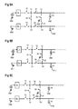
- FIG. 4 shows an exemplary block diagram of such a combined method, which starts with a block 401 denoting a transmission cycle. During such transmission cycle, the AC signal is transmitted from the transmitter electrode E1 to the receiver electrode E2 and the detection, whether a sense object is present at the electrodes E1, E2 is based on the received signal, as described before.
- the following block 402 denotes a capacitance measurement cycle.
- different capacitance values at the nodes T1, T2, R1, R2 are measured and used for either calibration of the touch sensing system or detection of a sense object or both.
- a sleep cycle may be performed, during which no measurement or detection is performed in order to save power.
- the sleep cycle can also be omitted, if desired, such that a next transmission cycle immediately follows.
- the capacitance values to be measured depend on the presence of a sense object at the first and the second electrode E1, E2.
- a differentiation can be made between three basic cases.
- case A no sense object is present at the electrodes E1, E2.
- case B a sense object is present at the electrodes E1, E2 but is not connected to the reference potential terminal GND.
- the sense object has no common ground with the touch sensing system.
- case C a sense object is also present at the first and the second electrode E1, E2 but is grounded, i.e. has a connection to the reference potential terminal of the touch sensing system.
- This situation of case C may for example be present if the touch sensing system is included in a device which is connected to an AC power plug, for example by a charger, and the sense object, for example a human body, is in contact with the ground terminal of this AC supply.
- Figure 5 shows switching configurations of the touch sensing system for case A
- Figure 6 shows switching configurations for case B
- Figure 7 shows switching configurations for case C.
- switches S2, S4 and S5 are closed while switches S1, S3, S6, S7 are open.
- the transmitter nodes T1, T2 and the receiver nodes R1, R2 are commonly connected to both the first and the second electrode E1, E2, which are not shown here for a better overview.
- the nodes T1, T2, R1, R2 are separated from the signal generator Tx and the signal receiver Rx, respectively.
- the touch sensing system is electrically open at the electrode side, denoted by the dashed line.
- the switching configuration of Figure 5A is set in a first measuring period in order to measure a first capacitance value at at least one of the nodes T1, T2, R1, R2.
- a capacitance between the respective measuring node and the reference potential terminal GND can be measured in order to determine a first capacitance value Ctot.
- an average can be build from the different measurements. For example, a first measurement is performed at the first transmitter node T1 and a second measurement is performed at the first receiver node R1.
- Figure 5B shows a switching configuration for a second measuring period, during which a second capacitance value Crm at at least one of the first receiver node R1 and the second receiver node R2 is measured.
- the first and the second receiver node R1, R2 are connected together and to the receiver electrode E2 by means of the closed switch S4.
- the transmitter electrode E1 is grounded by switch S6, which connects the second transmitter node T2 to the reference potential terminal GND.
- the remaining switches S1, S2, S3, S5 are held open if the capacitance measurement of the second capacitance value Crm is performed at both the first and the second receiver node R1, R2, averaging can be performed as described before.
- Figure 5C shows a third switching configuration for a third measuring period, which is similar to the switching configuration of Figure 5B but intended for use of capacitance measurement at the transmitter side.
- the first and the second transmitter node T1, T2 are connected to the transmitter electrode E1 by closed switch S2.
- Receiver electrode E2 is connected to the ground potential terminal by closed switch S7.
- Switches S1, S3, S4, S5 are open.
- This switching configuration is used in a third measuring period, during which a third capacitance value Ctm is measured at at least one of the first transmitter node T1 and the second transmitter node T2. In particular, a capacitance to the reference potential terminal GND is measured.
- the measured capacitance values Ctot, Crm and Ctm can be used as reference values for calibration of the touch sensing system.
- Figure 6 shows various switching configurations for case B, if a sense object is present but not grounded.
- serially connected capacitances Cst, Csr result between the first and the second electrode E1, E2 or between the second transmitter node T2 and the second receiver node R2, respectively.
- a switching configuration of the touch sensing system in Figure 6A is the same as in Figure 5A . Furthermore, the same measurement is performed as in Figure 5A in a first measuring period, resulting in a first capacitance value Ctot. However, as the receiver side and the transmitter side are connected together by switch S5, the series connection of the capacitances Cst, Csr of the sense object are bridged or shorted, such that the influence of the sense object on the measurement during the first measuring period is eliminated. The measured first capacitance value Ctot can be used for further processing.
- a switching configuration of Figure 6c is the same as in Figure 5c for measuring a third capacitance value Ctm in a third measuring period.
- this measurement is influenced by the presence of the sense object, namely the existence of capacitances Cst, Csr due to the three measurements, the actual reference values without the influence of the sense object can be calculated from the measured capacitance values.
- CTOT Ctot
- CR Crm - Ctm + Ctot / 2
- CT Ctm - Crm + Ctot / 2
- FIG 7 shows various switching configurations for case C, in which a sense object is present and connected to the reference potential terminal GND.
- corresponding switching configurations are used in Figure 7A, Figure 7B and Figure 7C , respectively.
- a respective capacitance value can be measured in each of the three measuring periods or switching configurations, respectively.
- the influence of the resulting capacitances Cst, Csr is not eliminated in any of the switching configurations.
- the capacitances Cst, Csr will add to the capacitances being there without the sense object being present.
- a measurement of the receiver capacitance at receiver nodes R1 and/or R2 will be influenced by the capacitance Csr while the capacitance Cst is grounded.
- a capacitance measurement at the transmitter nodes T1 and/or T2 is influenced by the capacitance Cst, whereas the capacitance Csr is grounded.
- case C a change of capacitance may be detected during the capacitance measurement, which indicates the presence of a sense object.
- Csr the influence of the resulting capacitances
- Cst cannot be calculated out, an updating of stored reference values CTOT, CR, CT is not possible.
- case C usually is a rare case, in particular if the touch sensing system is used in a mobile device which has no connection to a common ground with the user of the mobile device.
- the knowledge of the three cases can be used to detect a sense object and to perform a calibration of reference values, in particular in combination with the transmission measurement described before.
- FIG 8 shows a more detailed block diagram of a method for operating a touch sensing system, based on the block diagram of Figure 4 .
- a transmitter/receiver measurement is performed in order to determine a receiver level in response to an AC signal provided by the signal generator Tx.
- a threshold comparison is performed based on the signal level at the signal receiver Rx.
- the received signal level is compared to a reference level which depends on the calibration of the touch sensing system, as described before. If the difference between the received signal and the reference level is greater than the threshold, the presence of a sense object can be detected. In this case, it is continued with block 811 which denotes the previously described case B of a sense object being present but having no common ground connection to the touch sensing system. If the presence of an object cannot be determined in block 805, it is continued with block 813 denoting that either case A or case C may be present. Blocks 801, 803 and 805 correspond to the transmission cycle 401.
- a capacitance measurement is performed in block 815.
- the capacitance measurement includes the first measuring period, the second measuring period and the third measuring period, as described before in conjunction with Figure 5 , Figure 6 and Figure 7 .
- the reference values can be updated in block 817 according to the calculations described in conjunction with Figure 6 .
- both the detection of the object being present and the calibration of the touch sensing system can be performed.
- the cycle can be ended or a sleep cycle can be performed in block 403. After that, the method can be repeated by starting again at the transmission cycle 401.
- both case A or case C are possible cases.
- the measured capacitance values Ctot, Crm, Ctm can be compared to the stored reference values in order to detect whether a sense object is present or not in blocks 819, 821. For example, a difference between measured capacitance values Ctot, Crm, Ctm and the reference values CTOT, CR, CT is calculated in block 819. One or more of the respective differences is respectively compared to respective threshold which is indicative for a sense object being present.
- the measured capacitance value can be used to update the reference values, as described before in conjunction with Figure 5 .
- the threshold comparison in block 821 determines that a sense object is present, it is continued with block 827, denoting case C. Hence, only the presence of the sense object can be detected, while calibrating of the touch sensing system is omitted in this case.
- the capacitance measurement makes it possible to detect the presence of the sense object, which could not be detected with the transmission method in block 401.
- the comparison of the measured capacitance values Ctot, Crm, Ctm with the reference values CTOT, CR, CT is able to detect whether the values of the measured capacitances exceeds the stored reference values. Furthermore, this comparison makes it possible to retrieve information on how much the value of each capacitance exceeds the stored values. If a proper threshold is chosen to keep a measurement tolerance, an accurate detection can be achieved to detect a sense object.
- capacitance measurement cycle 402 is able to perform both calibration and detection.
- the touch sensing system can be calibrated even if a sense object is present. This provides a more continuous calibration.
Landscapes
- Engineering & Computer Science (AREA)
- General Engineering & Computer Science (AREA)
- Theoretical Computer Science (AREA)
- Human Computer Interaction (AREA)
- Physics & Mathematics (AREA)
- General Physics & Mathematics (AREA)
- Electronic Switches (AREA)
- Position Input By Displaying (AREA)
Priority Applications (3)
| Application Number | Priority Date | Filing Date | Title |
|---|---|---|---|
| EP11186563.0A EP2587352A1 (fr) | 2011-10-25 | 2011-10-25 | Système de détection tactile et procédé de fonctionnement d'un système de détection tactile |
| US14/354,119 US9304644B2 (en) | 2011-10-25 | 2012-10-05 | Touch sensing system and method for operating a touch sensing system |
| PCT/EP2012/069786 WO2013060565A1 (fr) | 2011-10-25 | 2012-10-05 | Système tactile et procédé de fonctionnement d'un système tactile |
Applications Claiming Priority (1)
| Application Number | Priority Date | Filing Date | Title |
|---|---|---|---|
| EP11186563.0A EP2587352A1 (fr) | 2011-10-25 | 2011-10-25 | Système de détection tactile et procédé de fonctionnement d'un système de détection tactile |
Publications (1)
| Publication Number | Publication Date |
|---|---|
| EP2587352A1 true EP2587352A1 (fr) | 2013-05-01 |
Family
ID=46970347
Family Applications (1)
| Application Number | Title | Priority Date | Filing Date |
|---|---|---|---|
| EP11186563.0A Withdrawn EP2587352A1 (fr) | 2011-10-25 | 2011-10-25 | Système de détection tactile et procédé de fonctionnement d'un système de détection tactile |
Country Status (3)
| Country | Link |
|---|---|
| US (1) | US9304644B2 (fr) |
| EP (1) | EP2587352A1 (fr) |
| WO (1) | WO2013060565A1 (fr) |
Families Citing this family (20)
| Publication number | Priority date | Publication date | Assignee | Title |
|---|---|---|---|---|
| US11327599B2 (en) | 2011-04-26 | 2022-05-10 | Sentons Inc. | Identifying a contact type |
| US9189109B2 (en) | 2012-07-18 | 2015-11-17 | Sentons Inc. | Detection of type of object used to provide a touch contact input |
| US10198097B2 (en) | 2011-04-26 | 2019-02-05 | Sentons Inc. | Detecting touch input force |
| US9477350B2 (en) | 2011-04-26 | 2016-10-25 | Sentons Inc. | Method and apparatus for active ultrasonic touch devices |
| US9639213B2 (en) | 2011-04-26 | 2017-05-02 | Sentons Inc. | Using multiple signals to detect touch input |
| US9099971B2 (en) | 2011-11-18 | 2015-08-04 | Sentons Inc. | Virtual keyboard interaction using touch input force |
| EP2780782B1 (fr) | 2011-11-18 | 2020-05-13 | Sentons Inc. | Retour d'information haptique localisé |
| US10235004B1 (en) | 2011-11-18 | 2019-03-19 | Sentons Inc. | Touch input detector with an integrated antenna |
| US9348468B2 (en) | 2013-06-07 | 2016-05-24 | Sentons Inc. | Detecting multi-touch inputs |
| US9459715B1 (en) | 2013-09-20 | 2016-10-04 | Sentons Inc. | Using spectral control in detecting touch input |
| US9417729B2 (en) * | 2014-06-09 | 2016-08-16 | Atmel Corporation | Charge compensation during touch sensing |
| US10048811B2 (en) | 2015-09-18 | 2018-08-14 | Sentons Inc. | Detecting touch input provided by signal transmitting stylus |
| JP2018022445A (ja) * | 2016-08-05 | 2018-02-08 | 株式会社ジャパンディスプレイ | 検出装置、及びタッチ検出機能付き表示装置 |
| US10908741B2 (en) | 2016-11-10 | 2021-02-02 | Sentons Inc. | Touch input detection along device sidewall |
| US10296144B2 (en) | 2016-12-12 | 2019-05-21 | Sentons Inc. | Touch input detection with shared receivers |
| US10126877B1 (en) | 2017-02-01 | 2018-11-13 | Sentons Inc. | Update of reference data for touch input detection |
| US10585522B2 (en) * | 2017-02-27 | 2020-03-10 | Sentons Inc. | Detection of non-touch inputs using a signature |
| US11580829B2 (en) | 2017-08-14 | 2023-02-14 | Sentons Inc. | Dynamic feedback for haptics |
| US11009411B2 (en) | 2017-08-14 | 2021-05-18 | Sentons Inc. | Increasing sensitivity of a sensor using an encoded signal |
| TWI835570B (zh) * | 2023-02-23 | 2024-03-11 | 群光電子股份有限公司 | 人機介面裝置 |
Citations (2)
| Publication number | Priority date | Publication date | Assignee | Title |
|---|---|---|---|---|
| US20080265914A1 (en) * | 2007-04-24 | 2008-10-30 | Kenichi Matsushima | Proximity detector and proximity detecting method |
| US20100060608A1 (en) * | 2008-09-10 | 2010-03-11 | Apple Inc. | Correction of parasitic capacitance effect in touch sensor panels |
Family Cites Families (5)
| Publication number | Priority date | Publication date | Assignee | Title |
|---|---|---|---|---|
| US7145552B2 (en) * | 2003-10-22 | 2006-12-05 | Solectron Corporation | Electric field proximity keyboards and detection systems |
| US20110043478A1 (en) * | 2008-02-27 | 2011-02-24 | Kenichi Matsushima | Proximity detection device and proximity detection method |
| US8030914B2 (en) * | 2008-12-29 | 2011-10-04 | Motorola Mobility, Inc. | Portable electronic device having self-calibrating proximity sensors |
| JP5191452B2 (ja) * | 2009-06-29 | 2013-05-08 | 株式会社ジャパンディスプレイウェスト | タッチパネルの駆動方法、静電容量型タッチパネルおよびタッチ検出機能付き表示装置 |
| US9086768B2 (en) * | 2012-04-30 | 2015-07-21 | Apple Inc. | Mitigation of parasitic capacitance |
-
2011
- 2011-10-25 EP EP11186563.0A patent/EP2587352A1/fr not_active Withdrawn
-
2012
- 2012-10-05 WO PCT/EP2012/069786 patent/WO2013060565A1/fr not_active Ceased
- 2012-10-05 US US14/354,119 patent/US9304644B2/en not_active Expired - Fee Related
Patent Citations (2)
| Publication number | Priority date | Publication date | Assignee | Title |
|---|---|---|---|---|
| US20080265914A1 (en) * | 2007-04-24 | 2008-10-30 | Kenichi Matsushima | Proximity detector and proximity detecting method |
| US20100060608A1 (en) * | 2008-09-10 | 2010-03-11 | Apple Inc. | Correction of parasitic capacitance effect in touch sensor panels |
Also Published As
| Publication number | Publication date |
|---|---|
| US9304644B2 (en) | 2016-04-05 |
| WO2013060565A1 (fr) | 2013-05-02 |
| US20140368464A1 (en) | 2014-12-18 |
Similar Documents
| Publication | Publication Date | Title |
|---|---|---|
| US9304644B2 (en) | Touch sensing system and method for operating a touch sensing system | |
| US10003334B2 (en) | Capacitative sensor system | |
| US8552994B2 (en) | Method and apparatus to measure self-capacitance using a single pin | |
| EP3640779B1 (fr) | Circuit de détection de capacité, puce tactile et dispositif électronique | |
| US10790822B2 (en) | Switching arrangement and method for a capacitive sensor | |
| US11650696B2 (en) | Noise detection circuit, self-capacitance detection method, touch chip, and electronic device | |
| JP6121397B2 (ja) | 携帯デバイスへの接近の検出のための測定デバイスおよび方法 | |
| US7880479B2 (en) | Capacitive sensor with alternating current power immunity | |
| WO2019144303A1 (fr) | Circuit de détection de capacité, appareil tactile et équipement terminal | |
| CN110596465B (zh) | 电容检测电路、触控装置和终端设备 | |
| US12000876B2 (en) | Capacitive sensing | |
| US9261546B2 (en) | Touch sensing circuit and method | |
| JP5890406B2 (ja) | 携帯デバイスの把持の検出のためのセンサデバイスおよび方法ならびに携帯デバイス | |
| US20230275583A1 (en) | Touch or proximity sensing system and method | |
| KR20150110717A (ko) | 전압 측정 장치 | |
| JP2018060502A (ja) | 入力装置 | |
| CN101738542A (zh) | 抗干扰的电容检测装置及方法 | |
| JP2012084453A (ja) | 静電容量スイッチ | |
| JP2008198063A (ja) | 座標位置検出装置 | |
| US20190155441A1 (en) | Touch sensor circuit and touch sensor method | |
| US20200057524A1 (en) | Touch sensing device and touch sensing method | |
| EP2722985A1 (fr) | Procédé de mesure différentielle des niveaux de voltage de change de capacité | |
| JP4920728B2 (ja) | 容量判別装置及び静電容量式タッチパネル | |
| TW201306480A (zh) | 用於偵測握持手持裝置之感測裝置及方法 | |
| EP2552022A1 (fr) | Circuit de détection et son procédé de fonctionnement |
Legal Events
| Date | Code | Title | Description |
|---|---|---|---|
| PUAI | Public reference made under article 153(3) epc to a published international application that has entered the european phase |
Free format text: ORIGINAL CODE: 0009012 |
|
| AK | Designated contracting states |
Kind code of ref document: A1 Designated state(s): AL AT BE BG CH CY CZ DE DK EE ES FI FR GB GR HR HU IE IS IT LI LT LU LV MC MK MT NL NO PL PT RO RS SE SI SK SM TR |
|
| AX | Request for extension of the european patent |
Extension state: BA ME |
|
| 17P | Request for examination filed |
Effective date: 20131029 |
|
| RBV | Designated contracting states (corrected) |
Designated state(s): AL AT BE BG CH CY CZ DE DK EE ES FI FR GB GR HR HU IE IS IT LI LT LU LV MC MK MT NL NO PL PT RO RS SE SI SK SM TR |
|
| STAA | Information on the status of an ep patent application or granted ep patent |
Free format text: STATUS: THE APPLICATION IS DEEMED TO BE WITHDRAWN |
|
| 18D | Application deemed to be withdrawn |
Effective date: 20170503 |