EP2587414B1 - Verpacktes RFID-Etikett für kleine Vorrichtungen - Google Patents
Verpacktes RFID-Etikett für kleine Vorrichtungen Download PDFInfo
- Publication number
- EP2587414B1 EP2587414B1 EP12189629.4A EP12189629A EP2587414B1 EP 2587414 B1 EP2587414 B1 EP 2587414B1 EP 12189629 A EP12189629 A EP 12189629A EP 2587414 B1 EP2587414 B1 EP 2587414B1
- Authority
- EP
- European Patent Office
- Prior art keywords
- transponder
- pair
- clip
- encapsulation module
- base receptacle
- Prior art date
- Legal status (The legal status is an assumption and is not a legal conclusion. Google has not performed a legal analysis and makes no representation as to the accuracy of the status listed.)
- Active
Links
Images


Classifications
-
- G—PHYSICS
- G06—COMPUTING OR CALCULATING; COUNTING
- G06K—GRAPHICAL DATA READING; PRESENTATION OF DATA; RECORD CARRIERS; HANDLING RECORD CARRIERS
- G06K19/00—Record carriers for use with machines and with at least a part designed to carry digital markings
- G06K19/06—Record carriers for use with machines and with at least a part designed to carry digital markings characterised by the kind of the digital marking, e.g. shape, nature, code
- G06K19/067—Record carriers with conductive marks, printed circuits or semiconductor circuit elements, e.g. credit or identity cards also with resonating or responding marks without active components
- G06K19/07—Record carriers with conductive marks, printed circuits or semiconductor circuit elements, e.g. credit or identity cards also with resonating or responding marks without active components with integrated circuit chips
- G06K19/077—Constructional details, e.g. mounting of circuits in the carrier
- G06K19/07749—Constructional details, e.g. mounting of circuits in the carrier the record carrier being capable of non-contact communication, e.g. constructional details of the antenna of a non-contact smart card
- G06K19/07798—Constructional details, e.g. mounting of circuits in the carrier the record carrier being capable of non-contact communication, e.g. constructional details of the antenna of a non-contact smart card part of the antenna or the integrated circuit being adapted for rupturing or breaking, e.g. record carriers functioning as sealing devices for detecting not-authenticated opening of containers
-
- A—HUMAN NECESSITIES
- A61—MEDICAL OR VETERINARY SCIENCE; HYGIENE
- A61B—DIAGNOSIS; SURGERY; IDENTIFICATION
- A61B90/00—Instruments, implements or accessories specially adapted for surgery or diagnosis and not covered by any of the groups A61B1/00 - A61B50/00, e.g. for luxation treatment or for protecting wound edges
- A61B90/90—Identification means for patients or instruments, e.g. tags
- A61B90/98—Identification means for patients or instruments, e.g. tags using electromagnetic means, e.g. transponders
-
- G—PHYSICS
- G06—COMPUTING OR CALCULATING; COUNTING
- G06K—GRAPHICAL DATA READING; PRESENTATION OF DATA; RECORD CARRIERS; HANDLING RECORD CARRIERS
- G06K19/00—Record carriers for use with machines and with at least a part designed to carry digital markings
- G06K19/06—Record carriers for use with machines and with at least a part designed to carry digital markings characterised by the kind of the digital marking, e.g. shape, nature, code
- G06K19/067—Record carriers with conductive marks, printed circuits or semiconductor circuit elements, e.g. credit or identity cards also with resonating or responding marks without active components
- G06K19/07—Record carriers with conductive marks, printed circuits or semiconductor circuit elements, e.g. credit or identity cards also with resonating or responding marks without active components with integrated circuit chips
- G06K19/077—Constructional details, e.g. mounting of circuits in the carrier
- G06K19/07749—Constructional details, e.g. mounting of circuits in the carrier the record carrier being capable of non-contact communication, e.g. constructional details of the antenna of a non-contact smart card
- G06K19/0775—Constructional details, e.g. mounting of circuits in the carrier the record carrier being capable of non-contact communication, e.g. constructional details of the antenna of a non-contact smart card arrangements for connecting the integrated circuit to the antenna
- G06K19/07752—Constructional details, e.g. mounting of circuits in the carrier the record carrier being capable of non-contact communication, e.g. constructional details of the antenna of a non-contact smart card arrangements for connecting the integrated circuit to the antenna using an interposer
-
- Y—GENERAL TAGGING OF NEW TECHNOLOGICAL DEVELOPMENTS; GENERAL TAGGING OF CROSS-SECTIONAL TECHNOLOGIES SPANNING OVER SEVERAL SECTIONS OF THE IPC; TECHNICAL SUBJECTS COVERED BY FORMER USPC CROSS-REFERENCE ART COLLECTIONS [XRACs] AND DIGESTS
- Y10—TECHNICAL SUBJECTS COVERED BY FORMER USPC
- Y10T—TECHNICAL SUBJECTS COVERED BY FORMER US CLASSIFICATION
- Y10T29/00—Metal working
- Y10T29/49—Method of mechanical manufacture
- Y10T29/49002—Electrical device making
- Y10T29/49117—Conductor or circuit manufacturing
- Y10T29/49124—On flat or curved insulated base, e.g., printed circuit, etc.
- Y10T29/4913—Assembling to base an electrical component, e.g., capacitor, etc.
Definitions
- the present invention relates to a transponder clip, an encapsulation module for holding the transponder clip and a method for activation and deactivation of the transponder clip for identifying and tracking a small sized device. More particularly the invention relates to a transponder clip including a miniature passive RFID tag, an encapsulation module for holding the transponder clip and also adapted to be attached to a small sized device or instrument and a related method for attaching the encapsulation module holding the transponder clip to the small sized device.
- Radio Frequency Identification also referred to as RFID is a well known Technology for auto-identification and tracking inventory, assets, people etc.
- An RFID tag consisting of a unique id is attached to a device or asset thereby providing a unique identification to the device or asset.
- An RFID reader is provided that interrogates the device by wirelessly reading the attached RFID tag using RF field.
- the RFID tag attached to the device receives the RF field from the RFID reader and returns back the unique id.
- This technology is implemented in a plurality of industries such as logistics and transportation, Retail, healthcare industry, and the like for improving the tracking process through traceability of each device or asset particularly small size and high volume devices such as implantable screws in a cost effective manner.
- the medical device OEMs (Original Equipment Manufacturers) deliver an assortment of implantable/non-implantable devices in a single kit form to individual hospitals. Such devices may be small in size and may be used in many surgical operations like spine, shoulder joint, and the like. The OEMs then bill the hospital based on actual number of such devices used.
- RFID tags are typically attached to each kit containing a plurality of small sized devices and such kits are tracked during outward & inwards movement in the warehouse.
- the small sized devices contained in the kit are not being tracked in such a manner as such devices are beholden to a large sized carrier kit on which a larger dimension RFID tag is placed.
- tracking small size devices using a low cost RFID tag from a distance greater than at least 6-8 inches and a large number of devices simultaneously is a major issue.
- EP1755073A2 describes RFID inlays and methods of their manufacture.
- US2006/0214791A1 describes an RFID tag that is integrated into a button-type, substantially cylindrically-shaped housing with a portion for attaching the tag to an object to be identified through radio frequency identification techniques.
- US2007/0222232A1 describes a security sealing device including a sealing element, an integrated circuit and an antenna connected to the integrated circuit, the integrated circuit and the antenna forming an RFID circuit.
- WO2006/102678A1 describes a sensor which may be used to detect a previous or current change of state and report the change by an RFID tag.
- Yet another objective of the present disclosure is to provide a convenient method for automatic deactivation or "killing" the transponder clip on detachment before the small sized device such as a medical implant is used.
- an encapsulation module according to claim 1.
- a method of encapsulating a transponder clip according to claim 13.
- the present disclosure is related to a unique transponder clip comprising a UHF passive RFID tag, an encapsulation module and method of attaching the encapsulation module enclosing the transponder clip to small sized devices.
- the small sized device may be a small sized medical device such as bone screw, spine screw implants.
- the transponder clip described herein is enclosed in an encapsulation module that is then attached to a small sized device thereby facilitating auto-identification and tracking of the small sized device.
- a transponder clip may be provided that consists of an RFID transponder IC bonded on a small printed circuit board (PCB).
- the RFID transponder IC may be a low cost UHF passive RFID tag.
- Two antenna traces are embedded on two edges of the printed circuit board (PCB).
- the antenna traces may be made up of a conductive metal such as copper.
- the printed circuit board may be made up of a paper like thin substrate.
- the encapsulation module adapted to enclose transponder clip may consist of a top caddy and a base receptacle.
- the top caddy is adapted to be adjustably fixed over the base receptacle by employing a fitting mechanism such as snap fit mechanism.
- the base receptacle may include a cavity for accepting the transponder clip. Further, the base receptacle may include a single notch for unique positioning of the transponder clip.
- the encapsulation module may enable the transponder clip including the RFID tag to be sterilized or autoclaved along with the small sized device.
- the base receptacle also includes a pair of special leg fixtures and at least one extended leg fixture.
- the pair of special leg fixtures and the extended leg fixture includes a cavity at their respective lateral surfaces.
- the special leg fixtures may be hollow and may have a cavity across their length.
- the pair of special leg fixtures and the extended leg fixture may be diametrically opposite to each other and provided at the bottom of the base receptacle.
- the encapsulation module may be made up of medical plastic such as Radel-R, PCTFE, and the like.
- a pair of embedded metallic strips is provided that may be embedded directly into the base receptacle. One end of the metallic strips may be exposed at the cavity in the transponder receiving part of the base receptacle and thereon extend through the hollow space provided in the special leg fixtures.
- the embedded metallic strips extending through the hollow space provided in the pair of special leg fixtures may run within the encapsulation module in a given pattern and may get exposed minimally at the end of the special leg fixtures.
- the embedded metallic strips may get minimally exposed at the lateral surface towards the end of the special leg fixtures such that the exposed parts face each other.
- the embedded metallic strip may be made up of an electricity conducting metal such as titanium or copper.
- the embedded metallic strips may facilitate as antenna trace thereby enabling the RFID tag operation and improve RFID tag performance due to its extended length.
- the embedded metallic strips enable the transponder clip enclosed in the encapsulation module to be functional even in the proximity of metal taking into consideration the distortion of RF field in the proximity of metal.
- the embedded metallic strips reduce the dependence on the angle and orientation of reading the transponder clip enclosed in the encapsulation module to be read by the RFI reader.
- the encapsulation module may include a wire harness. Such a wire harness may pass through the cavities provided in the lateral surfaces of the pair of special leg fixtures and the extended leg fixture. The wire harness may tightly hold a small sized device between the pair of special leg fixtures and the extended leg fixture. Further, the wire harness pulls the individual special leg fixtures towards each other thereby getting the metallic strip extended across the hollow space provided in the pair of special leg fixtures in contact with each other.
- the wire harness may enable deactivating or auto-killing of the RFID tag when the encapsulation module is removed from the small sized device thereby breaking the wire harness and deactivating the RFID tag.
- the unique miniature transponder clip may be manually fitted on the exposed portions of the metallic strips at the base receptacle.
- the transponder clip may not be physically bonded with the exposed portions of the metallic strips using a technique such as soldering.
- the transponder clip may get electrical connection to the metallic strips by parasitic capacitive coupling.
- the length, width & orientation of the pair of metallic strips may facilitate a greater distance of reading the RFID tag of the transponder clip.
- the RFID tag of the transponder clip may be read by an RFID reader even at a distance of greater than 8 inches.
- the transponder clip may be activated when the wire harness passing through the cavities of the pair of special leg fixtures and the extended leg fixture pulls the pair of special leg fixtures towards each other thereby electrically coupling the exposed end of the metallic strips facing each other and thus completing the circuit.
- the transponder clip may be deactivated by cutting or breaking the wire harness thereby releasing the pair of special leg fixtures in their original parallel position that uncouples the exposed end of the metallic strips and breaks the circuit.
- the present invention also gives a feature to improve the performance of the transponder clip by providing a pair of elongated metallic strips from the base of the encapsulation module.
- the encapsulation module enables the transponder clip to be autoclaved as the clip is enclosed in the encapsulation module.
- An automatic "killing" or deactivation mechanism is also provided when the encapsulation module is removed from device.
- a transponder clip is embedded inside a special purpose encapsulation module, which is attached to a small sized device. While designing of encapsulation module the physical and operational orientation factors such as space, auto-cleavability of attachment, effect of RF field due to proximity of metal, and the like are taken into consideration. Moreover, the encapsulation module described in the present application enables longer range of auto-identification and reduces the dependence on the angle & orientation of transponder clip reading. The encapsulation module also significantly enhances the throughput particularly when attached to a physically small & metallic device such as bone screw, spine screw, and the like, it results in major benefit in circumventing inadvertent loss of these devices.
- FIG. 1 illustrates a miniature transponder clip (100) according to an embodiment of the present invention.
- the transponder clip (100) includes an RFID transponder IC (101), a small antenna (102) and a printed circuit board (103).
- RFID transponder IC (101) is bonded on the printed circuit board (103) preferably without any antenna pattern.
- the small antenna (102) may be designed as a pair of copper traces on two edges of the printed circuit board (103).
- the RFID transponder IC (101) may be a UHF passive RFID tag.
- the printed circuit board (103) may be made of substrate including but not limited to paper type substrate, a plastic type substrate, and the like.
- the RFID transponder IC (101) may be a miniature RFID tag with dimensions less than 10mm X10mm.
- the transponder clip (100) may be provided with a single notch for orientation fixation.
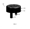
- FIG. 2 illustrates an encapsulation module (200).
- the encapsulation module (200) broadly includes a top caddy (201), a base receptacle (202), a pair of special leg fixtures (203), and at least one support leg fixture (204).
- the encapsulation module (200) may be made up of medical plastic such as Radel-R, PCTFE, and the like.
- the encapsulation module (200) may be made up of radio-transparent material.
- the top caddy (201) is adapted to be adjustably fixed over the base receptacle (202) by employing a fitting mechanism such as snap fit mechanism.
- the base receptacle (202) may include a cavity for accepting the transponder clip (100).
- the transponder clip (100) may be fitted in the base receptacle (202) of the encapsulation module (200) and the top caddy (201) is then fitted on top of the base receptacle (202).
- the encapsulation module (200) may utilize a snaps-fit mechanism for fitting the top caddy (201) into the base receptacle (202).
- the fitting mechanism utilized by the encapsulation module (200) may facilitate a vacuum environment to the RFID tag enclosed between the top caddy (201) and base receptacle (202) hence providing an autoclavability condition along with environmental protection to the enclosed RFID tag.
- a rubber casket may additionally be provided at the bottom of the top caddy (201) that may enable the transponder clip to be fixed between the top caddy and the base receptacle.
- the pair of special leg fixtures (203) and support leg fixture (204) enables attaching the encapsulation module (200) over a small sized device.
- the pair of special leg fixtures (203) and support leg fixture (204) may include a hole each on the leg fixtures preferably on the lateral surface for incorporating a wire harness through said holes.
- the small sized device may be a small sized medical device such as an implant.
- the small sized medical device may be a bone implant screw, spine implant screw, and the like.
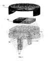
- FIG 3 illustrates an exploded view of the encapsulation module enclosing the transponder clip in accordance with an embodiment.
- the top caddy (301) is adapted to be attached to the base receptacle (303) by using a snap fit mechanism such as annular snap fit, cantilever snap fit, or torsional snap fit.
- a pair of protruding cantilever snaps is provided in the top caddy (301) and a pair of respective cavities in the base receptacle (303).
- the transponder clip (302) is provided a single notch and the base receptacle (303) may include a single cavity that may be adapted to accept the notch provided in the transponder clip (100) thereby enabling the transponder clip to be uniquely fitted in the encapsulation module.
- a pair of special leg fixtures (304) and a support leg fixture (305) is provided for attaching the encapsulation module over a small sized device.
- the pair of special leg fixtures (304) and the support leg fixture (305) include a cavity at their respective lateral surfaces. Further, the special leg fixtures are hollow and have a cavity across their length.
- the pair of special leg fixtures (304) and the support leg fixture (305) are diametrically opposite to each other and provided at the bottom of the base receptacle (303).
- a pair of embedded metallic strips (306) is provided that may be embedded directly into the base receptacle (303). One end of the metallic strips (306) is exposed at the cavity in the transponder receiving part of the base receptacle.
- the pair of metallic strips (306) extends through the hollow space provided in the special leg fixtures.
- the embedded metallic strips (306) extending through the hollow space provided in the pair of special leg fixtures may run within the encapsulation module in a given pattern and gets exposed minimally at the end of the special leg fixtures.
- the embedded metallic strips may get minimally exposed at the lateral surface towards the end of the special leg fixtures such that the exposed parts face each other.
- the embedded metallic strip may be made up of an electricity conducting metal such as titanium or copper.
- the embedded metallic strips may facilitate as antenna trace thereby enabling the RFID tag operation and improve RFID tag performance due to its extended length.
- the embedded metallic strips enable the transponder clip enclosed in the encapsulation module to be functional even in the proximity of metal taking into consideration the distortion of RF field in the proximity of metal.
- the embedded metallic strips reduce the dependence on the angle and orientation of reading the transponder clip enclosed in the encapsulation module to be read by the RFI reader.
- the transponder may be made operational only by a wire harness.
- the wire harness tightly holds a small sized device between the pair of special leg fixtures (304) and a support leg fixture (305). Further, the wire harness pulls the individual special leg fixtures (304) towards each other thereby getting the metallic strip extended across the hollow space provided in the pair of special leg fixtures in contact with each other.
- the wire harness may enable deactivating or auto-killing of the transponder clip when the encapsulation module is removed from the small sized device thereby breaking the wire harness and deactivating the transponder clip.
- FIG 4 illustrates an embodiment of the present invention wherein the embedded metallic strips (402) is embedded in the bottom corners of the base receptacle (401).
- One individual embedded metallic strip may be exposed on each of the proximity leg fixtures.
- the embedded metallic strip may run through the hollow space provided in the pair of special leg fixtures.
- each leg may run separate embedded metallic strip from two corners of the base receptacle (401).
- the embedded metallic strip may facilitate improved RFID tag performance due to its extended length especially in the proximity of a metal body thereby overcoming any distortion to the RF field in the proximity of the metal body.
Landscapes
- Engineering & Computer Science (AREA)
- Health & Medical Sciences (AREA)
- Microelectronics & Electronic Packaging (AREA)
- Life Sciences & Earth Sciences (AREA)
- Surgery (AREA)
- Physics & Mathematics (AREA)
- Computer Hardware Design (AREA)
- Theoretical Computer Science (AREA)
- General Physics & Mathematics (AREA)
- Molecular Biology (AREA)
- Pathology (AREA)
- Animal Behavior & Ethology (AREA)
- General Health & Medical Sciences (AREA)
- Public Health (AREA)
- Veterinary Medicine (AREA)
- Oral & Maxillofacial Surgery (AREA)
- Nuclear Medicine, Radiotherapy & Molecular Imaging (AREA)
- Medical Informatics (AREA)
- Heart & Thoracic Surgery (AREA)
- Biomedical Technology (AREA)
- Electromagnetism (AREA)
- Near-Field Transmission Systems (AREA)
Claims (14)
- Einkapselungsmodul (200) zum Einkapseln eines Transponderclips (100, 302), der zum Identifizieren und Nachverfolgen einer Vorrichtung eingesetzt wird, wobei das Einkapselungsmodul angepasst ist, an der Vorrichtung befestigt zu werden, wobei das Einkapselungsmodul Folgendes umfasst:einen Grundbehälter (202, 303, 401) mit einem Hohlraum zum Aufnehmen des Transponderclips (100, 302);einen oberen Träger (201, 301), angepasst, um unter Einsatz eines Einpassmechanismus einstellbar über dem Grundbehälter (202, 303, 401) eingepasst zu werden;ein Paar spezielle Beinvorrichtungen (203, 304) und wenigstens eine Stützbeinvorrichtung (204, 305), gekoppelt mit dem Grundbehälter (202, 303, 401);ein Paar im Grundbehälter (202, 303, 401) eingebettete Metallstreifen (306, 402),einen Kabelbaum, durch ein Loch in jeder aus dem Paar von speziellen Beinvorrichtungen (203, 304) und in der wenigstens einen Stützbeinvorrichtung (204, 305) hindurch befestigt, so dass der Kabelbaum minimal freiliegende distale Enden des Paars von metallischen Clips elektrisch verbindet und somit die Transponderclips aktiviert; undwobei proximale Enden des Paars Metallstreifen (306, 402) im Hohlraum des Grundbehälters (202, 303, 401) minimal freiliegen und angepasst sind, elektrisch mit einem Paar Antennenbahnen (102) des Transponderclips (100, 302) verbunden zu werden, wobei sich jeder Metallstreifen (306) durch eine spezielle Beinvorrichtung (203, 304) aus dem Paar von speziellen Beinvorrichtungen (203, 304) hindurch erstreckt, wobei das Paar von speziellen Beinvorrichtungen (203, 304) und die wenigstens eine Stützbeinvorrichtung (204, 305) über den Kabelbaum durch das Loch in jeder aus dem Paar von speziellen Beinvorrichtungen (203, 304) und in der wenigstens einen Stützbeinvorrichtung (204, 305) elektrisch miteinander verbunden sind.
- Einkapselungsmodul (200) nach Anspruch 1, ferner umfassend den Transponderclip (100, 302), wobei der Transponderclip (100, 302) einen RFID-Transponder-IC (101), eine Leiterplatte (103) und ein Paar Antennenbahnen (102) aufweist, wobei das Paar Antennenbahnen (102) an zwei Kanten der Leiterplatte (103) eingebettet ist und der RFID-Transponder-IC (101) elektrisch mit der Leiterplatte (103) und dem Paar Antennenbahnen (102) verbunden ist.
- Einkapselungsmodul (200) nach Anspruch 2, wobei der RFID-Transponder-IC (101) ein UHF-passives RFID-Etikett ist.
- Einkapselungsmodul (200) nach einem der vorhergehenden Ansprüche, wobei das Paar Antennenspuren (102) aus einem leitfähigen Material hergestellt ist, ausgewählt aus einer Gruppe bestehend aus Kupfer, Aluminium und Titan.
- Einkapselungsmodul (200) nach einem der Ansprüche 2 bis 4, wobei die Leiterplatte (103) aus einem papierähnlichen dünnen Substrat hergestellt ist.
- Einkapselungsmodul (200) nach einem der vorhergehenden Ansprüche, wobei das Einkapselungsmodul (200) aus einem medizinischen Kunststoff hergestellt ist, ausgewählt aus einer Gruppe bestehend aus Radel-R und PCTFE.
- Einkapselungsmodul (200) nach einem der vorhergehenden Ansprüche, wobei der obere Träger (201, 301) angepasst ist, durch einen Schnappmechanismus einstellbar über dem Grundbehälter (202, 303, 401) befestigt zu sein.
- Einkapselungsmodul (200) nach einem der vorhergehenden Ansprüche, wobei der Transponderclip (100, 302) ein RFID-Etikett ist.
- Einkapselungsmodul (200) nach einem der vorhergehenden Ansprüche, wobei der Transponderclip (100, 302) eine einzelne Kerbe aufweist und der Grundbehälter (202, 303, 401) eine Kerbenvertiefung aufweist, um den Transponderclip (100, 302) im Einkapselungsmodul (200) eindeutig zu positionieren.
- Einkapselungsmodul (200) nach einem der vorhergehenden Ansprüche, wobei das Paar von speziellen Beinvorrichtungen (203, 304) und die wenigstens eine Stützbeinvorrichtung (204, 305) einander diametral gegenüber angeordnet sind.
- Einkapselungsmodul (200) nach einem der vorhergehenden Ansprüche, wobei das Paar von eingebetteten Metallstreifen (306, 402) ein elektrisch leitfähiges Metall umfasst, ausgewählt aus der Gruppe bestehend aus Titan und Kupfer.
- Einkapselungsmodul (200) nach einem der vorhergehenden Ansprüche, wobei das Paar von Metallstreifen (306, 402) an der lateralen Oberfläche zum Ende der speziellen Beinvorrichtungen (203, 304) hin derart minimal freiliegt, dass die freiliegenden Metallstreifenteile zu einander hinweisen.
- Verfahren zum Einkapseln eines Transponderclips (100, 302), der zum Identifizieren und Nachverfolgen einer Vorrichtung eingesetzt wird, wobei das Verfahren Folgendes umfasst:Einpassen des Transponderclips (100, 302) in einen Grundbehälter (202, 303, 401) derart, dass ein Paar Antennenbahnen (102) des Transponderclips (100, 302) elektrisch mit minimal freiliegenden proximalen Enden eines Paars von im Grundbehälter (202, 303, 401) eingebetteten Metallstreifen (306, 402) verbunden ist;Einpassen eines oberen Trägers (201, 301) über dem Grundbehälter (202, 303, 401) durch Verwenden eines Einpassmechanismus; undBefestigen eines Kabelbaums durch ein an einem distalen Ende eines Paars von speziellen Beinvorrichtungen (203, 304) und an wenigstens einer Stützbeinvorrichtung (204, 305) bereitgestelltes Loch derart an der Vorrichtung, dass der Kabelbaum minimal freiliegende distale Enden des Paars von Metallstreifen (306, 402) elektrisch verbindet, wodurch der Transponderclip (100, 302) aktiviert wird.
- Verfahren nach Anspruch 13, ferner umfassend das Deaktivieren des Transponderclips (100, 302) durch Lösen des Kabelbaums, so dass die minimal freiliegenden Enden des Paars von Metallstreifen (306, 402) entkoppelt werden.
Applications Claiming Priority (1)
| Application Number | Priority Date | Filing Date | Title |
|---|---|---|---|
| IN3052MU2011 | 2011-10-31 |
Publications (2)
| Publication Number | Publication Date |
|---|---|
| EP2587414A1 EP2587414A1 (de) | 2013-05-01 |
| EP2587414B1 true EP2587414B1 (de) | 2015-06-17 |
Family
ID=47115479
Family Applications (1)
| Application Number | Title | Priority Date | Filing Date |
|---|---|---|---|
| EP12189629.4A Active EP2587414B1 (de) | 2011-10-31 | 2012-10-23 | Verpacktes RFID-Etikett für kleine Vorrichtungen |
Country Status (2)
| Country | Link |
|---|---|
| US (1) | US8960559B2 (de) |
| EP (1) | EP2587414B1 (de) |
Cited By (1)
| Publication number | Priority date | Publication date | Assignee | Title |
|---|---|---|---|---|
| EP4041117B1 (de) * | 2019-09-24 | 2024-03-06 | Dentsply Sirona Inc. | Dentalwerkzeug mit einem miniaturisierten rfid-etikett |
Families Citing this family (6)
| Publication number | Priority date | Publication date | Assignee | Title |
|---|---|---|---|---|
| US10660726B2 (en) | 2015-01-21 | 2020-05-26 | Covidien Lp | Sterilizable wirelessly detectable objects for use in medical procedures and methods of making same |
| WO2016171750A1 (en) * | 2015-04-20 | 2016-10-27 | Thomson Licensing | Electronic device with antenna mount |
| NL2016488B1 (en) * | 2016-03-24 | 2017-10-06 | Van Straten Medical B V | An RFID tag mounted or mountable on surgical or medical equipment or on a surgical or medical instrument. |
| RU2754986C1 (ru) * | 2017-10-16 | 2021-09-08 | Гкл Энтернасьональ Сарл | Закрывающий элемент |
| CN114270002A (zh) | 2019-09-20 | 2022-04-01 | 开利公司 | 用于锁定和解锁的方法和系统 |
| CN110944451A (zh) * | 2019-12-13 | 2020-03-31 | 京信通信技术(广州)有限公司 | 电路板固定组件、射频器件及天线 |
Family Cites Families (14)
| Publication number | Priority date | Publication date | Assignee | Title |
|---|---|---|---|---|
| WO1996003713A1 (en) * | 1994-07-28 | 1996-02-08 | Westinghouse Electric Corporation | Security access circuit using embedded antennas |
| US6026818A (en) | 1998-03-02 | 2000-02-22 | Blair Port Ltd. | Tag and detection device |
| US6940408B2 (en) * | 2002-12-31 | 2005-09-06 | Avery Dennison Corporation | RFID device and method of forming |
| US7336243B2 (en) * | 2003-05-29 | 2008-02-26 | Sky Cross, Inc. | Radio frequency identification tag |
| WO2006046157A1 (en) * | 2004-10-28 | 2006-05-04 | Assa Abloy Identification Technology Group Ab | Security sealing device comprising a rfid tag |
| US20060241399A1 (en) | 2005-02-10 | 2006-10-26 | Fabian Carl E | Multiplex system for the detection of surgical implements within the wound cavity |
| US7256699B2 (en) * | 2005-03-24 | 2007-08-14 | Sdgi Holdings, Inc. | Button-type RFID tag |
| US20060214789A1 (en) * | 2005-03-24 | 2006-09-28 | Joshua Posamentier | Tamper detection with RFID tag |
| US7262701B1 (en) * | 2005-05-23 | 2007-08-28 | National Semiconductor Corporation | Antenna structures for RFID devices |
| US20070040688A1 (en) * | 2005-08-16 | 2007-02-22 | X-Cyte, Inc., A California Corporation | RFID inlays and methods of their manufacture |
| DE102006055744A1 (de) * | 2006-11-25 | 2008-05-29 | Atmel Germany Gmbh | Antenne für einen rückstreubasierten RFID-Transponder |
| EP2062234A1 (de) | 2007-03-12 | 2009-05-27 | Rf Surgical Systems, Inc. | Transpondergehäuse und gerät zur markierung von werkzeugen |
| US8338722B2 (en) * | 2008-06-23 | 2012-12-25 | RFID Mexico, S.A. DE C.V. | Tag enclosing structure |
| US9226686B2 (en) | 2009-11-23 | 2016-01-05 | Rf Surgical Systems, Inc. | Method and apparatus to account for transponder tagged objects used during medical procedures |
-
2012
- 2012-10-23 EP EP12189629.4A patent/EP2587414B1/de active Active
- 2012-10-25 US US13/660,437 patent/US8960559B2/en active Active
Cited By (1)
| Publication number | Priority date | Publication date | Assignee | Title |
|---|---|---|---|---|
| EP4041117B1 (de) * | 2019-09-24 | 2024-03-06 | Dentsply Sirona Inc. | Dentalwerkzeug mit einem miniaturisierten rfid-etikett |
Also Published As
| Publication number | Publication date |
|---|---|
| US20130105585A1 (en) | 2013-05-02 |
| EP2587414A1 (de) | 2013-05-01 |
| US8960559B2 (en) | 2015-02-24 |
Similar Documents
| Publication | Publication Date | Title |
|---|---|---|
| EP2587414B1 (de) | Verpacktes RFID-Etikett für kleine Vorrichtungen | |
| EP3146479B1 (de) | Rfid-etikett-anordnung und chirurgisches instrument | |
| EP2210219B1 (de) | Wiederverwendbares hermetisches rfid-etikett für den medizinischen gebrauch | |
| EP3569062B1 (de) | Wundfreiliegende multifunktionale tierohrmarke mit schnellanlegung | |
| US8624721B2 (en) | Method and apparatus for embedding a transmitter into a tool, and a system for monitoring the tool | |
| US7213767B2 (en) | Sleeve-type RFID tag | |
| US7256699B2 (en) | Button-type RFID tag | |
| US8427321B2 (en) | Physiological sensor system with automatic authentication and validation by means of a radio frequency identification protocol with an integrated RFID interrogator system | |
| US9911019B2 (en) | Medical device identification system | |
| US7760099B2 (en) | Radio frequency verification system and device | |
| US20170172701A1 (en) | RFID Transponder For A Medical Instrument And/Or For An Endoscope, Medical Instrument And/Or Endoscope, And Assembly Method | |
| BR0212735A (pt) | Etiqueta combinada | |
| US10149736B2 (en) | Deposition of RFID tags | |
| US20070159337A1 (en) | Modular RFID tag | |
| US9785878B2 (en) | RFID tag and method of attaching the same | |
| WO2008130386A1 (en) | Information tag | |
| EP2223268A1 (de) | Seitengeladenes rfid-etikett mit kurzgeschlossenem patch | |
| WO2007056503A2 (en) | Information devices | |
| BR102019010479A2 (pt) | Identificação, rastreabilidade e monitoramento de instrumentais cirúrgicos por radiofrequência em uhf durante ato cirúrgico, no ciclo limpeza, esterilização e manutenção e identificação, rastreabilidade e monitoramento de ferramentas e objetos metálicos por radiofrequência operando em uhf | |
| JP2009080762A (ja) | 非接触式データキャリアの取り付け構造 |
Legal Events
| Date | Code | Title | Description |
|---|---|---|---|
| PUAI | Public reference made under article 153(3) epc to a published international application that has entered the european phase |
Free format text: ORIGINAL CODE: 0009012 |
|
| 17P | Request for examination filed |
Effective date: 20121023 |
|
| AK | Designated contracting states |
Kind code of ref document: A1 Designated state(s): AL AT BE BG CH CY CZ DE DK EE ES FI FR GB GR HR HU IE IS IT LI LT LU LV MC MK MT NL NO PL PT RO RS SE SI SK SM TR |
|
| AX | Request for extension of the european patent |
Extension state: BA ME |
|
| RIC1 | Information provided on ipc code assigned before grant |
Ipc: G06K 19/077 20060101AFI20141219BHEP |
|
| GRAP | Despatch of communication of intention to grant a patent |
Free format text: ORIGINAL CODE: EPIDOSNIGR1 |
|
| INTG | Intention to grant announced |
Effective date: 20150205 |
|
| GRAS | Grant fee paid |
Free format text: ORIGINAL CODE: EPIDOSNIGR3 |
|
| RAP1 | Party data changed (applicant data changed or rights of an application transferred) |
Owner name: TATA CONSULTANCY SERVICES LIMITED |
|
| GRAA | (expected) grant |
Free format text: ORIGINAL CODE: 0009210 |
|
| AK | Designated contracting states |
Kind code of ref document: B1 Designated state(s): AL AT BE BG CH CY CZ DE DK EE ES FI FR GB GR HR HU IE IS IT LI LT LU LV MC MK MT NL NO PL PT RO RS SE SI SK SM TR |
|
| REG | Reference to a national code |
Ref country code: GB Ref legal event code: FG4D |
|
| REG | Reference to a national code |
Ref country code: CH Ref legal event code: EP |
|
| REG | Reference to a national code |
Ref country code: AT Ref legal event code: REF Ref document number: 732293 Country of ref document: AT Kind code of ref document: T Effective date: 20150715 |
|
| REG | Reference to a national code |
Ref country code: DE Ref legal event code: R096 Ref document number: 602012008004 Country of ref document: DE |
|
| REG | Reference to a national code |
Ref country code: IE Ref legal event code: FG4D |
|
| REG | Reference to a national code |
Ref country code: FR Ref legal event code: PLFP Year of fee payment: 4 |
|
| PG25 | Lapsed in a contracting state [announced via postgrant information from national office to epo] |
Ref country code: LT Free format text: LAPSE BECAUSE OF FAILURE TO SUBMIT A TRANSLATION OF THE DESCRIPTION OR TO PAY THE FEE WITHIN THE PRESCRIBED TIME-LIMIT Effective date: 20150617 Ref country code: FI Free format text: LAPSE BECAUSE OF FAILURE TO SUBMIT A TRANSLATION OF THE DESCRIPTION OR TO PAY THE FEE WITHIN THE PRESCRIBED TIME-LIMIT Effective date: 20150617 Ref country code: NO Free format text: LAPSE BECAUSE OF FAILURE TO SUBMIT A TRANSLATION OF THE DESCRIPTION OR TO PAY THE FEE WITHIN THE PRESCRIBED TIME-LIMIT Effective date: 20150917 Ref country code: HR Free format text: LAPSE BECAUSE OF FAILURE TO SUBMIT A TRANSLATION OF THE DESCRIPTION OR TO PAY THE FEE WITHIN THE PRESCRIBED TIME-LIMIT Effective date: 20150617 |
|
| REG | Reference to a national code |
Ref country code: AT Ref legal event code: MK05 Ref document number: 732293 Country of ref document: AT Kind code of ref document: T Effective date: 20150617 |
|
| REG | Reference to a national code |
Ref country code: LT Ref legal event code: MG4D Ref country code: NL Ref legal event code: MP Effective date: 20150617 |
|
| PG25 | Lapsed in a contracting state [announced via postgrant information from national office to epo] |
Ref country code: RS Free format text: LAPSE BECAUSE OF FAILURE TO SUBMIT A TRANSLATION OF THE DESCRIPTION OR TO PAY THE FEE WITHIN THE PRESCRIBED TIME-LIMIT Effective date: 20150617 Ref country code: BG Free format text: LAPSE BECAUSE OF FAILURE TO SUBMIT A TRANSLATION OF THE DESCRIPTION OR TO PAY THE FEE WITHIN THE PRESCRIBED TIME-LIMIT Effective date: 20150917 Ref country code: LV Free format text: LAPSE BECAUSE OF FAILURE TO SUBMIT A TRANSLATION OF THE DESCRIPTION OR TO PAY THE FEE WITHIN THE PRESCRIBED TIME-LIMIT Effective date: 20150617 Ref country code: GR Free format text: LAPSE BECAUSE OF FAILURE TO SUBMIT A TRANSLATION OF THE DESCRIPTION OR TO PAY THE FEE WITHIN THE PRESCRIBED TIME-LIMIT Effective date: 20150918 |
|
| PG25 | Lapsed in a contracting state [announced via postgrant information from national office to epo] |
Ref country code: EE Free format text: LAPSE BECAUSE OF FAILURE TO SUBMIT A TRANSLATION OF THE DESCRIPTION OR TO PAY THE FEE WITHIN THE PRESCRIBED TIME-LIMIT Effective date: 20150617 |
|
| PG25 | Lapsed in a contracting state [announced via postgrant information from national office to epo] |
Ref country code: PT Free format text: LAPSE BECAUSE OF FAILURE TO SUBMIT A TRANSLATION OF THE DESCRIPTION OR TO PAY THE FEE WITHIN THE PRESCRIBED TIME-LIMIT Effective date: 20151019 Ref country code: ES Free format text: LAPSE BECAUSE OF FAILURE TO SUBMIT A TRANSLATION OF THE DESCRIPTION OR TO PAY THE FEE WITHIN THE PRESCRIBED TIME-LIMIT Effective date: 20150617 Ref country code: AT Free format text: LAPSE BECAUSE OF FAILURE TO SUBMIT A TRANSLATION OF THE DESCRIPTION OR TO PAY THE FEE WITHIN THE PRESCRIBED TIME-LIMIT Effective date: 20150617 Ref country code: IS Free format text: LAPSE BECAUSE OF FAILURE TO SUBMIT A TRANSLATION OF THE DESCRIPTION OR TO PAY THE FEE WITHIN THE PRESCRIBED TIME-LIMIT Effective date: 20151017 Ref country code: SK Free format text: LAPSE BECAUSE OF FAILURE TO SUBMIT A TRANSLATION OF THE DESCRIPTION OR TO PAY THE FEE WITHIN THE PRESCRIBED TIME-LIMIT Effective date: 20150617 Ref country code: RO Free format text: LAPSE BECAUSE OF NON-PAYMENT OF DUE FEES Effective date: 20150617 Ref country code: CZ Free format text: LAPSE BECAUSE OF FAILURE TO SUBMIT A TRANSLATION OF THE DESCRIPTION OR TO PAY THE FEE WITHIN THE PRESCRIBED TIME-LIMIT Effective date: 20150617 Ref country code: PL Free format text: LAPSE BECAUSE OF FAILURE TO SUBMIT A TRANSLATION OF THE DESCRIPTION OR TO PAY THE FEE WITHIN THE PRESCRIBED TIME-LIMIT Effective date: 20150617 |
|
| REG | Reference to a national code |
Ref country code: DE Ref legal event code: R097 Ref document number: 602012008004 Country of ref document: DE |
|
| PLBE | No opposition filed within time limit |
Free format text: ORIGINAL CODE: 0009261 |
|
| STAA | Information on the status of an ep patent application or granted ep patent |
Free format text: STATUS: NO OPPOSITION FILED WITHIN TIME LIMIT |
|
| PG25 | Lapsed in a contracting state [announced via postgrant information from national office to epo] |
Ref country code: IT Free format text: LAPSE BECAUSE OF FAILURE TO SUBMIT A TRANSLATION OF THE DESCRIPTION OR TO PAY THE FEE WITHIN THE PRESCRIBED TIME-LIMIT Effective date: 20150617 Ref country code: DK Free format text: LAPSE BECAUSE OF FAILURE TO SUBMIT A TRANSLATION OF THE DESCRIPTION OR TO PAY THE FEE WITHIN THE PRESCRIBED TIME-LIMIT Effective date: 20150617 |
|
| 26N | No opposition filed |
Effective date: 20160318 |
|
| REG | Reference to a national code |
Ref country code: CH Ref legal event code: PL |
|
| PG25 | Lapsed in a contracting state [announced via postgrant information from national office to epo] |
Ref country code: MC Free format text: LAPSE BECAUSE OF FAILURE TO SUBMIT A TRANSLATION OF THE DESCRIPTION OR TO PAY THE FEE WITHIN THE PRESCRIBED TIME-LIMIT Effective date: 20150617 |
|
| REG | Reference to a national code |
Ref country code: IE Ref legal event code: MM4A |
|
| PG25 | Lapsed in a contracting state [announced via postgrant information from national office to epo] |
Ref country code: LI Free format text: LAPSE BECAUSE OF NON-PAYMENT OF DUE FEES Effective date: 20151031 Ref country code: CH Free format text: LAPSE BECAUSE OF NON-PAYMENT OF DUE FEES Effective date: 20151031 |
|
| PG25 | Lapsed in a contracting state [announced via postgrant information from national office to epo] |
Ref country code: SI Free format text: LAPSE BECAUSE OF FAILURE TO SUBMIT A TRANSLATION OF THE DESCRIPTION OR TO PAY THE FEE WITHIN THE PRESCRIBED TIME-LIMIT Effective date: 20150617 |
|
| PG25 | Lapsed in a contracting state [announced via postgrant information from national office to epo] |
Ref country code: IE Free format text: LAPSE BECAUSE OF NON-PAYMENT OF DUE FEES Effective date: 20151023 |
|
| REG | Reference to a national code |
Ref country code: FR Ref legal event code: PLFP Year of fee payment: 5 |
|
| PG25 | Lapsed in a contracting state [announced via postgrant information from national office to epo] |
Ref country code: BE Free format text: LAPSE BECAUSE OF FAILURE TO SUBMIT A TRANSLATION OF THE DESCRIPTION OR TO PAY THE FEE WITHIN THE PRESCRIBED TIME-LIMIT Effective date: 20150617 |
|
| PG25 | Lapsed in a contracting state [announced via postgrant information from national office to epo] |
Ref country code: SM Free format text: LAPSE BECAUSE OF FAILURE TO SUBMIT A TRANSLATION OF THE DESCRIPTION OR TO PAY THE FEE WITHIN THE PRESCRIBED TIME-LIMIT Effective date: 20150617 Ref country code: HU Free format text: LAPSE BECAUSE OF FAILURE TO SUBMIT A TRANSLATION OF THE DESCRIPTION OR TO PAY THE FEE WITHIN THE PRESCRIBED TIME-LIMIT; INVALID AB INITIO Effective date: 20121023 |
|
| PG25 | Lapsed in a contracting state [announced via postgrant information from national office to epo] |
Ref country code: SE Free format text: LAPSE BECAUSE OF FAILURE TO SUBMIT A TRANSLATION OF THE DESCRIPTION OR TO PAY THE FEE WITHIN THE PRESCRIBED TIME-LIMIT Effective date: 20150617 Ref country code: NL Free format text: LAPSE BECAUSE OF FAILURE TO SUBMIT A TRANSLATION OF THE DESCRIPTION OR TO PAY THE FEE WITHIN THE PRESCRIBED TIME-LIMIT Effective date: 20150617 Ref country code: CY Free format text: LAPSE BECAUSE OF FAILURE TO SUBMIT A TRANSLATION OF THE DESCRIPTION OR TO PAY THE FEE WITHIN THE PRESCRIBED TIME-LIMIT Effective date: 20150617 |
|
| PG25 | Lapsed in a contracting state [announced via postgrant information from national office to epo] |
Ref country code: MT Free format text: LAPSE BECAUSE OF FAILURE TO SUBMIT A TRANSLATION OF THE DESCRIPTION OR TO PAY THE FEE WITHIN THE PRESCRIBED TIME-LIMIT Effective date: 20150617 |
|
| REG | Reference to a national code |
Ref country code: FR Ref legal event code: PLFP Year of fee payment: 6 |
|
| PG25 | Lapsed in a contracting state [announced via postgrant information from national office to epo] |
Ref country code: TR Free format text: LAPSE BECAUSE OF FAILURE TO SUBMIT A TRANSLATION OF THE DESCRIPTION OR TO PAY THE FEE WITHIN THE PRESCRIBED TIME-LIMIT Effective date: 20150617 Ref country code: MK Free format text: LAPSE BECAUSE OF FAILURE TO SUBMIT A TRANSLATION OF THE DESCRIPTION OR TO PAY THE FEE WITHIN THE PRESCRIBED TIME-LIMIT Effective date: 20150617 |
|
| REG | Reference to a national code |
Ref country code: FR Ref legal event code: PLFP Year of fee payment: 7 |
|
| PG25 | Lapsed in a contracting state [announced via postgrant information from national office to epo] |
Ref country code: AL Free format text: LAPSE BECAUSE OF FAILURE TO SUBMIT A TRANSLATION OF THE DESCRIPTION OR TO PAY THE FEE WITHIN THE PRESCRIBED TIME-LIMIT Effective date: 20150617 |
|
| PGFP | Annual fee paid to national office [announced via postgrant information from national office to epo] |
Ref country code: DE Payment date: 20211029 Year of fee payment: 10 |
|
| REG | Reference to a national code |
Ref country code: DE Ref legal event code: R119 Ref document number: 602012008004 Country of ref document: DE |
|
| P01 | Opt-out of the competence of the unified patent court (upc) registered |
Effective date: 20230526 |
|
| PG25 | Lapsed in a contracting state [announced via postgrant information from national office to epo] |
Ref country code: DE Free format text: LAPSE BECAUSE OF NON-PAYMENT OF DUE FEES Effective date: 20230503 |
|
| PGFP | Annual fee paid to national office [announced via postgrant information from national office to epo] |
Ref country code: GB Payment date: 20260227 Year of fee payment: 14 |
|
| PGFP | Annual fee paid to national office [announced via postgrant information from national office to epo] |
Ref country code: LU Payment date: 20260227 Year of fee payment: 14 |
|
| PGFP | Annual fee paid to national office [announced via postgrant information from national office to epo] |
Ref country code: FR Payment date: 20260227 Year of fee payment: 14 |