EP2587510B1 - Schlüsselanordnung für eine elektronische Vorrichtung - Google Patents
Schlüsselanordnung für eine elektronische Vorrichtung Download PDFInfo
- Publication number
- EP2587510B1 EP2587510B1 EP12171135.2A EP12171135A EP2587510B1 EP 2587510 B1 EP2587510 B1 EP 2587510B1 EP 12171135 A EP12171135 A EP 12171135A EP 2587510 B1 EP2587510 B1 EP 2587510B1
- Authority
- EP
- European Patent Office
- Prior art keywords
- light
- key assembly
- light guide
- keycap
- mask
- Prior art date
- Legal status (The legal status is an assumption and is not a legal conclusion. Google has not performed a legal analysis and makes no representation as to the accuracy of the status listed.)
- Active
Links
Images


Classifications
-
- G—PHYSICS
- G06—COMPUTING OR CALCULATING; COUNTING
- G06F—ELECTRIC DIGITAL DATA PROCESSING
- G06F3/00—Input arrangements for transferring data to be processed into a form capable of being handled by the computer; Output arrangements for transferring data from processing unit to output unit, e.g. interface arrangements
- G06F3/01—Input arrangements or combined input and output arrangements for interaction between user and computer
- G06F3/02—Input arrangements using manually operated switches, e.g. using keyboards or dials
- G06F3/0202—Constructional details or processes of manufacture of the input device
-
- G—PHYSICS
- G02—OPTICS
- G02B—OPTICAL ELEMENTS, SYSTEMS OR APPARATUS
- G02B6/00—Light guides; Structural details of arrangements comprising light guides and other optical elements, e.g. couplings
- G02B6/0001—Light guides; Structural details of arrangements comprising light guides and other optical elements, e.g. couplings specially adapted for lighting devices or systems
- G02B6/0011—Light guides; Structural details of arrangements comprising light guides and other optical elements, e.g. couplings specially adapted for lighting devices or systems the light guides being planar or of plate-like form
- G02B6/0066—Light guides; Structural details of arrangements comprising light guides and other optical elements, e.g. couplings specially adapted for lighting devices or systems the light guides being planar or of plate-like form characterised by the light source being coupled to the light guide
- G02B6/0073—Light emitting diode [LED]
-
- G—PHYSICS
- G06—COMPUTING OR CALCULATING; COUNTING
- G06F—ELECTRIC DIGITAL DATA PROCESSING
- G06F1/00—Details not covered by groups G06F3/00 - G06F13/00 and G06F21/00
- G06F1/16—Constructional details or arrangements
- G06F1/1613—Constructional details or arrangements for portable computers
- G06F1/1633—Constructional details or arrangements of portable computers not specific to the type of enclosures covered by groups G06F1/1615 - G06F1/1626
- G06F1/1662—Details related to the integrated keyboard
-
- H—ELECTRICITY
- H01—ELECTRIC ELEMENTS
- H01H—ELECTRIC SWITCHES; RELAYS; SELECTORS; EMERGENCY PROTECTIVE DEVICES
- H01H13/00—Switches having rectilinearly-movable operating part or parts adapted for pushing or pulling in one direction only, e.g. push-button switch
- H01H13/70—Switches having rectilinearly-movable operating part or parts adapted for pushing or pulling in one direction only, e.g. push-button switch having a plurality of operating members associated with different sets of contacts, e.g. keyboard
- H01H13/83—Switches having rectilinearly-movable operating part or parts adapted for pushing or pulling in one direction only, e.g. push-button switch having a plurality of operating members associated with different sets of contacts, e.g. keyboard characterised by legends, e.g. Braille, liquid crystal displays, light emitting or optical elements
-
- H—ELECTRICITY
- H01—ELECTRIC ELEMENTS
- H01H—ELECTRIC SWITCHES; RELAYS; SELECTORS; EMERGENCY PROTECTIVE DEVICES
- H01H2219/00—Legends
- H01H2219/054—Optical elements
- H01H2219/06—Reflector
-
- H—ELECTRICITY
- H01—ELECTRIC ELEMENTS
- H01H—ELECTRIC SWITCHES; RELAYS; SELECTORS; EMERGENCY PROTECTIVE DEVICES
- H01H2219/00—Legends
- H01H2219/054—Optical elements
- H01H2219/062—Light conductor
-
- H—ELECTRICITY
- H01—ELECTRIC ELEMENTS
- H01H—ELECTRIC SWITCHES; RELAYS; SELECTORS; EMERGENCY PROTECTIVE DEVICES
- H01H2219/00—Legends
- H01H2219/054—Optical elements
- H01H2219/064—Optical isolation of switch sites
Definitions
- the present disclosure relates to electronic devices, and, more particularly, to key assemblies for electronic devices.
- Electronic devices often have a number of physical keys which may be used for inputting instructions to such devices.
- electronic devices In order to facilitate use of electronic devices in low lighting conditions, electronic devices sometimes backlight such physical keys.
- backlighting keys an effect known as light leak may sometimes occur. Light leak occurs when light is emitted from undesirable portions of the electronic device. This can result in unbalanced and unattractive backlighting of keys.
- a light source e.g. a light emitting diode
- a light guide foil is positioned underneath a set of keys and the light guide foil functions to spread out the light from the light source.
- a side-fire LED or similar source is used to inject light into the foil.
- side-fire LEDs tend to be costly. Top-fire LEDs are thus sometimes used as a light source to inject light into the foil; however, this arrangement presents difficulties when designing to ensure a shallow depth to the key assembly.
- Document US2009/260965 A1 discloses such a key assembly.
- the present disclosure describes a key assembly for an electronic device according to claim 1.
- the present application describes electronic devices that incorporate the key assembly described herein.
- LEDs light emitting diodes
- FIG. 1 shows a perspective view of an example electronic device 100.
- the electronic device 100 is a handheld mobile communication device.
- Such electronic devices may, in various example embodiments, include portable electronic devices such as mobile communication devices, including pagers, smartphones, cellular phones, global positioning system (GPS) navigation devices and other satellite navigation devices, wireless organizers, wireless personal digital assistants (PDA), desktop, netbook and notebook computers and tablet computers.
- the electronic devices may, in various embodiments, be devices without wireless communication capabilities such as PDAs, electronic gaming devices, digital photograph albums or picture frames, digital cameras or digital video recorders. These examples are intended to be nonlimiting.
- the electronic device 100 includes a housing 102 which contains various electronic components which control operation of the electronic device 100.
- Such electronic components may include, for example, one or more processors.
- Other example electronic components which may be housed in the housing 102 will be discussed in greater detail below.
- the electronic device 100 includes a physical keyboard or keypad 104.
- the keyboard or keypad 104 may be an alphanumeric keyboard or keypad which facilitates entry of alphanumeric characters into the electronic device 100.
- the keyboard or keypad 104 may be a QWERTY or DVORAK keyboard.
- the keyboard or keypad 104 includes a plurality of keys which are actuatable by a user to provide inputs to the electronic device 100.
- the physical keyboard or keypad 104 is exposed by the housing 102 through a front surface of the housing 102.
- the keyboard or keypad 104 is a sliding keyboard or foldout keyboard which is movable between an exposed position in which keys of the keyboard or keypad 104 are exposed and a protected position in which keys of the keyboard or keypad 104 are protected. That is, in the protected position, the keys of the keyboard or keypad 104 are hidden by other features of the electronic device 100.
- the electronic device 100 may be an electronic device which does not include a physical keyboard or keypad 104. Instead, alphanumeric input may be achieved through the use of a virtual keyboard displayed on a touchscreen of the electronic device 100.
- the housing 102 houses a display assembly 120.
- the display assembly 120 is disposed within the housing 102 facing the same direction as the keyboard or keypad 104.
- the electronic device 100 is oriented in a portrait orientation in which a left side 142 and a right side 140 of the electronic device 100 are longer than a top side 144 and a bottom side 146 of the electronic device 100.
- the key and display assembly 120 is disposed above the keyboard or keypad 104. That is, the key and display assembly 120 is located closer to the top side 144 than is the keyboard or keypad 104.
- the keyboard or keypad 104 is actuatable by a user's thumbs when the device 100 is cradled in a user's hands. It will be appreciated that this is an example orientation and that other configurations are possible.
- the display assembly 120 includes a display cover 152, which may also be referred to as a lens.
- the display cover 152 is transparent, permitting users to view the display screen, which is disposed beneath the display cover 152.
- the display cover 152 protects components disposed there below and inhibits debris and other contaminants from entering the electronic device 100.
- the display screen displays information in response to commands from one or more processors within the electronic device 100.
- the display cover 152 may include a touchscreen overlay for accepting touch screen inputs in one embodiment.
- the display screen may be, in some example embodiments, a liquid crystal display (LCD) module.
- the display screen may be another type of display device, such as an organic light emitting diode (OLED) module, a plasma display panel (PDP) module, or the like.
- OLED organic light emitting diode
- PDP plasma display panel
- the key assembly 193 includes a keycap 150 defining one or more function keys 106a, 106b, 106c, 106d.
- the keycap 150 may be integrally formed with the display cover 152.
- the keycap 150 is a separate element from the display cover 152.
- the keycap 150 is formed as multiple keycaps; for example, one keycap for each function key 106, or one keycap for each pair of function keys.
- the function keys 106a, 106b, 106c, 106d are configured to be depressed by a user of the electronic device 100 to input commands to the electronic device 100.
- there are four function keys 106 which are disposed horizontally between the left side 142 and the right side 140 of the electronic device 100.
- the function which is assigned to each function key 106a, 106b, 106c, 106d by the electronic device 100 may, in at least some example embodiments, vary based on the operating state of the electronic device 100.
- the function keys 106a, 106b, 106c, 106d include a first function key 106a, which may be a send key which may be used to input a command to initiate communications on the electronic device 100.
- the function keys 106a, 106b, 106c, 106d also include a second function key 106b, which may be a menu key which may be used to input a command to display a menu on a display screen of the electronic device 100.
- the function keys 106a, 106b, 106c, 106d also include a third function key 106c, which may be an escape key, and which may also be referred to as a back key.
- the escape key may be used to input a command to exit from an application, module or state or to input a command to return to a previous state, such as a previously viewed web page.
- the function keys 106a, 106b, 106c, 106d also include a fourth function key 106d, which may be an end or power key.
- the end or power key may be used to input a command to terminate an operating state, module or application running on the electronic device 102.
- the end or power key may be used to input a command to hang-up a call or to input a command to power down the electronic device 100.
- the function keys 106a, 106b, 106c, 106d each include one or more decorations 156a, 156b, 156c, 156d on the external surface of the keycap 150.
- the decorations 156a, 156b, 156c, 156d are comprised of icons, text, images, or other indicia which identify a function assigned to the function key 106a, 106b, 106c, 106d associated with that decoration 156a, 156b, 156c, 156d.
- a telephone icon is used to represent the send key
- the letter "M" is used to represent the menu key
- a back arrow icon is used to represent the escape key
- an on-cradle telephone icon is used to represent the end or power key.
- the decorations 156a, 156b, 156c, 156d are each associated with one of the function keys 106a, 106b, 106c, 106d.
- a first decoration 156a may be associated with the first function key 106a
- a second decoration 156b may be associated with the second function key 156b
- a third decoration 156c may be associated with the third function key 156c
- a fourth decoration 156d may be associated with the fourth function key 156d.
- the keycap 150 may be cantilever mounted at a first end 190 of the keycap 150. That is, the keycap 150 is supported at the first end 190 of the keycap 150.
- the first end 190 of the keycap 150 is the end of the keycap 150 which is nearest to the display cover 152.
- the keycap 150 and the display cover 152 may be a single component, which may be referred to as an integrated keycap/display cover.
- the key assembly 193 generally includes one or more electrical switches mounted within the housing 102 beneath the keycap 150.
- the electrical switches mounted beneath the keycap 150 are each associated with corresponding function keys 106a, 106b, 106c, 106d.
- the electrical switches are connected to one or more controllers, such as one or more processors associated with the electronic device 100 and provide input signals to the processors.
- the electrical switches are each associated with and aligned with corresponding keys.
- the keycap 150 may deflect at its second end 192, which is opposite the first end 190, in response to the application of an external force on the external surface of the keypad. When such a deflection occurs, the keycap 150 may actuate the electrical switch which is associated with the portion of the keycap where the external force was applied. In at least some example embodiments, the electrical switches are disposed beneath the second end 192 of the keycap.
- the electrical switches may be located in a position which permits them to be actuated by a portion of the keycap which is located between the second end 192 and the decorations 156a, 156b, 156c, 156d. By locating the electrical switches in this position, the space beneath the decorations 156a, 156b, 156c, 156d on the keycap 150 is not obstructed by the electrical switches. Locating the electrical switches away from the decorations 156a, 156b, 156c, 156d facilitates backlighting of the keycap 150.
- the electrical switches may be dome switches, in some embodiments.
- FIG. 1 shows a single piece keycap 150 that includes a plurality of function keys 106a, 106b, 106c, 106d.
- the key assembly may include features which prevent or inhibit movement of keys 106a, 106b, 106c, 106d, when the adjacent key is depressed.
- Such features may include, for example, indentations or grooves (not shown) on the interior surface of the keycap 150 between keys 106a, 106b, 106c, 106d which allows the keycap 150 to bend.
- the electronic device 100 may include additional input devices in addition to the input devices discussed above.
- the electronic device 100 includes a navigational input device 180.
- the keycap 150 defines a passageway through which the navigational input device 180 extends.
- the navigational input device 180 may be comprised of a trackpad. In other embodiments, the navigational input device 180 may be a trackball. Other navigational input devices 180 are also possible. In some cases, no navigational device may present in this location.
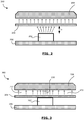
- FIG 2 diagrammatically illustrates a cross-sectional view of a portion of an example key assembly 200.
- the portion of the key assembly 200 includes an optical source, which in this example is a top-fire LED 202.
- the LED 202 is mounted or attached to a subsurface, such as a printed circuit board (PCB) 206 or other such substrate.
- the portion of the key assembly 200 includes a light guide 204 under a keycap 208.
- the LED 202 is spaced from the underside of the light guide 204 by a distance D.
- the light guide may include a light guide foil, such a polycarbonate or other type of moldable flexible plastic, or any other type of light guide, including hard-plastic light guides.
- the LED 202 emits light upwards generally directed towards the light guide 204.
- the light guide 204 functions to disperse the light such that the light that passes through the light guide 204 towards the keycap 208 is more uniformly distributed than the light incident on the underside of the light guide 204.
- the keycap 208 may be structured to permit at least a portion of light incident on its underside to pass through and exit through a decoration or diagram on its upper surface (not shown), thereby illuminating (backlighting) the decoration.
- the keycap 208 is structured to prevent light from exiting surfaces of the keycap other than through the decoration. This may be accomplished using foils, paints, or other techniques applied to the surface of the keycap 208 in some embodiments.
- the decorations and/or diagrams are non-opaque portions of the keycap 208.
- FIG. 3 shows another embodiment of a portion of an example key assembly 300.
- the key assembly 300 is constructed such that there is no gap between the LED 202 and the light guide 204. This may advantageously reduce the thickness of the key assembly 300, thereby enabling the creation of thinner electronic devices.
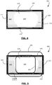
- FIG. 4 shows a top view of the top-fire LED 202.
- the LED 202 includes a housing 216, the edges of which are visible in the illustration, and a top surface 218 through which the LED 202 emits light. It will be noted, that the LED 202 is rectangular in structure with two long sides 220 and two short sides 222.
- the light emitted from the top-fire LED 202 is not a uniform spectrum across the entire top surface of the LED 202.
- the light emitted from the center portion of the LED 202 tends to be broad spectrum white light (generally indicated by reference number 210), whereas the areas furthest from the center, particularly near the short sides 222, tend to emit light that has a yellow tint (generally indicated by reference numbers 212 and 214).
- the present example depicts a rectangular LED
- the present application is not limited to rectangular LEDs.
- the problem of skewed colour spectrum at the edges of the LED top surface is particularly noticeable in rectangular LEDs, but can also occur in other shaped LEDs, including square and even round LEDs.
- the yellow tinted light at the edges of the top surface 218 tends to become visible when a reflector is placed in front of the LED top surface 218, such that a portion of the light emitted from the LED 202 is reflected back into the LED 202, causing the yellow-tinted areas of the LED to become more illuminated and, thus, to cause the light that eventually leaves the LED 202 to appear yellower at its edges.
- a key assembly like key assembly 200 ( FIG. 2 ), in which the LED 202 is spaced apart from the light guide 204 by a distance D, the light emitted from the central portion of LED 202 does not significantly reflect back into the LED and does not significantly illuminate the more yellow portions of the LED top surface 218. Accordingly, the yellowish light 212, 214 does not appear in the configuration shown in FIG. 2 .
- the LED 202 is in direct contact with the underside of the light guide 204, and the light emitting from the LED 202 is directly injected into the light guide 204.
- the net effect is an uneven dispersal of light within the light guide 204, such that the light exiting the upper side of the light guide 204 tends to be brighter in the region directly above the LED 202 (generally indicated by reference numeral 230), and tends to be dimmer in the region away from the LED 202 (generally indicated by reference numeral 232).
- the reduced dispersal also results in a yellow tint to portions of the light exiting the top side of the light guide 204.
- placing the light guide 204 directly atop the LED 204 without a significant gap between them may result in illuminated decorations in the keycap 208 that have shadowed areas and/or that have a yellow tint.
- tint is described as being yellow, with different types of LEDs other tints may occur depending on the construction and operation of the specific LED.
- FIG. 5 shows the top view of the example top-fire LED 202 with a mask 250.
- the mask 250 is affixed to the top surface 218 of the LED 202.
- the mask 250 is an opaque material having an aperture 252 through which light may pass. It may be referred to herein as an optical mask.
- the optical mask 250 is sized and positioned over the top surface 218 so as to line up the aperture with the white light emitting portion 210 of the top surface 218.
- the opaque material is generally positioned so as to block light from the yellow-tinted portions 212, 214 of the top surface 218.
- the optical mask 250 may be formed from opaque tape, in some embodiments. Other opaque materials may also be used.
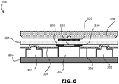
- FIG. 6 shows a cross-sectional view of a part of a stack-up of one example of the key assembly 300.
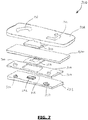
- FIG. 7 shows an exploded view of the stack-up of the example of the key assembly 300.
- Not all elements or components are necessarily shown in the example.
- adhesives, shims, chassis, or other such spacing and/or securing components are not necessarily illustrated.
- the thickness of elements has been exaggerated in this simplified diagram for ease of illustration.
- the keycap 208 is illustrated as a single piece having two keys.
- the two keys have non-opaque decorative indicia 310, 312 on the outer surface.
- the key assembly 300 includes a PCB 206 or other substrate on which are mounted two electrical switches (e.g. two dome switches) 302 and the top-fire LED 202.
- the mylar foil 304 may features plungers 306 above the respective dome switches 302.
- the mylar foil 304 also features an aperture so that the mylar foil 304 does not overlay the LED 202.
- the optical mask 250 sits atop the LED 202 top surface 218, positioned as explained above to block yellow light from entering the light guide 204.
- the aperture 252 within the optical mask 250 is aligned with the white-light emitting portion 210 of the LED 202 to allow that light to pass upwards into the light guide 204.
- the light guide 204 is directly atop the optical mask 250.
- the light guide 204 is also in contact with the plungers 306 of the mylar foil 304.
- the light guide 204 is a flexible light guide foil that may be shaped or formed as needed.
- the keycap 208 is positioned above and spaced apart from the light guide 204. Although not shown, the keycap 208 may include silicone or other foils on its underside.
- the key assembly 300 further includes a cover tape 320.
- the cover tape 320 is an opaque material adhered to a central portion of the top surface of the light guide 204.
- the cover tape 320 generally blocks light from escaping through the central portion of the light guide 204. This may prevent light leakage through the middle portion of the keycap 208.
- the keycap 208 may include a groove or other feature that increases the likelihood of light leakage between the keys.
- the keycap 208 may not be a continuous piece, and may be formed from separate pieces for each key, which poses the possibility of light leakage between keys.
- the cover tape 320 may have a partially mirrored undersurface facing the light guide 204 so as to direct any light incident on the cover tape 320 back into the light guide 204.
- the light guide 204 is constructed of a material that is transparent or, in some example embodiments, translucent.
- the light guide 302 may, in at least some example embodiments, be constructed of a clear plastic or silicone.
- the keycap 208 is an in-mould-decorated keycap.
- In-mould decoration is a type of plastic moulding which may be used for decorating plastic surfaces with color.
- In-mould decoration may be used to produce a keycap having a plastic body that transmits optical radiation and which has an artwork layer located on an external surface of the plastic body.
- the plastic body may be formed from a plastic that is generally translucent or transparent, such as a clear plastic.
- the artwork layer may include the one or more graphics (e.g. the non-opaque decorations 156a, 156b, 156c, 156d of FIG. 1 ) which are to be illuminated.
- the graphics e.g.
- the non-opaque decorations 156a, 156b, 156c, 156d) typically include at least a portion which is of a different color than the background color of the artwork layer.
- the decorations e.g. 156a, 156b, 156c, 156d
- the background color region provides the keycap 208 with a background color.
- the background color is the color that is applied to a large portion of the external surface of the keycap 208.
- the background color is, in at least some example embodiments, an opaque color, such as black. In other example embodiments, the background color may be a more translucent color, such as white. Other, colors may also be used.
- in-mould decoration is not used for providing graphics on the keys.
- Other techniques may be used to form the keycap 208.
- FIG. 8 shows another example embodiment of a key assembly 400.
- FIG. 8 shows a cross-sectional view of a part of a stack-up of this embodiment.
- key assembly 400 includes an optical mask 450 that is at least partially transparent and does not have an aperture.
- the optical mask 450 is a filter.
- the colour spectrum selected for filtering by the LED mask 450 may depend on the characteristics of the LED 202; however, in one embodiment the optical mask 450 is blue-transparent foil to filter out yellowish portions of the spectrum such that the light entering the light guide 204 is substantially cool white.
Landscapes
- Engineering & Computer Science (AREA)
- Physics & Mathematics (AREA)
- Theoretical Computer Science (AREA)
- General Physics & Mathematics (AREA)
- General Engineering & Computer Science (AREA)
- Computer Hardware Design (AREA)
- Human Computer Interaction (AREA)
- Microelectronics & Electronic Packaging (AREA)
- Optics & Photonics (AREA)
- Input From Keyboards Or The Like (AREA)
- Push-Button Switches (AREA)
Claims (15)
- Tastenanordnung (200, 300) für ein elektronisches Gerät, wobei die Tastenanordnung Folgendes umfasst:eine Quelle (202) optischer Strahlung mit einer Oberfläche (218), durch die in Gebrauch Licht emittiert wird,einen Lichtleiter (204) undeine Tastenkappe (208), die eine Taste definiert, wobei die Tastenkappe einen nicht-opaken Abschnitt aufweist,wobei der Lichtleiter (204) dazu dient, Licht derart auszubreiten, dass das Licht, das den Lichtleiter (204) hin zur Tastenkappe (208) durchquert, gleichmäßiger verteilt wird als das Licht, das auf die Unterseite des Lichtleiters (204) fällt,gekennzeichnet durch eine opake Maske (250), die einen Teil des in Gebrauch von der Quelle (202) optischer Strahlung emittierten Lichts blockiert,wobei die opake Maske (250) zwischen der Oberfläche (218) und dem Lichtleiter (204) angeordnet ist und der Lichtleiter (204) zwischen der opaken Maske (250) und der Tastenkappe (208) angeordnet ist, so dass die Tastenkappe (208) optische Strahlung empfängt, die von der Quelle (202) optischer Strahlung emittiert und nicht von der opaken Maske (250) blockiert wird.
- Tastenanordnung nach Anspruch 1, wobei die Quelle (202) optischer Strahlung eine Leuchtdiode (LED) ist.
- Tastenanordnung nach Anspruch 2, wobei die LED eine oben leuchtende LED ist, die das Licht an einer oberen Fläche (218) der LED emittiert.
- Tastenanordnung nach Anspruch 3, wobei die obere Fläche (218) der LED rechteckig ist und wobei die Abschnitte der oberen Fläche (218) der LED, die den kürzeren Seiten (222) des Rechtecks am nächsten sind, Licht mit einem farbigen Spektrum (212, 214) emittieren.
- Tastenanordnung nach Anspruch 4, wobei die Maske (250) die opake Maske umfasst, die eine in sich definierte Öffnung (252) aufweist, und wobei die Öffnung (252) über mindestens einem Abschnitt der oberen Fläche (218) positioniert ist und wobei mindestens ein Teil der opaken Maske die Abschnitte der oberen Fläche abdeckt, die das farbige Spektrum (212, 214) emittieren.
- Tastenanordnung nach einem der Ansprüche 1 bis 4, wobei die Maske (250) die opake Maske umfasst, die eine in sich definierte Öffnung (252) aufweist, und wobei die Öffnung über mindestens einem Abschnitt der Oberfläche (218) positioniert ist und wobei mindestens ein Teil der opaken Maske mindestens einen Abschnitt der Oberfläche (218) abdeckt.
- Tastenanordnung nach Anspruch 6, wobei die Quelle optischer Strahlung dafür gestaltet ist, durch einen Abschnitt der Oberfläche weißes Licht zu emittieren, und dafür gestaltet ist, durch einen oder mehrere andere Abschnitte (212, 214) der Oberfläche (218) farbiges Licht zu emittieren, und wobei die opake Maske (250) dafür positioniert ist, ihre Öffnung (252) über dem Abschnitt aufzuweisen, der dafür gestaltet ist, weißes Licht zu emittieren, und dafür, die Abschnitte (212, 214) zu blockieren, die dafür gestaltet sind, farbiges Licht zu emittieren.
- Tastenanordnung nach einem der Ansprüche 1 bis 7, wobei die opake Maske ein opakes Band ist, das an der Oberfläche (218) der Quelle (202) optischer Strahlung befestigt ist.
- Tastenanordnung nach Anspruch 8, wobei das opake Band ein ausgestanztes schwarzes Band umfasst, das an der Oberfläche (218) der Quelle (202) optischer Strahlung anhaftet.
- Tastenanordnung nach einem der Ansprüche 1 bis 9, wobei der Lichtleiter (204) eine Lichtleiterfolie umfasst.
- Tastenanordnung nach einem der Ansprüche 1 bis 10, wobei der Lichtleiter (204) eine untere Fläche aufweist, die zur Maske (250) weist, und der Lichtleiter (204) an seiner unteren Fläche Haftstoff aufweist und wobei der Haftstoff den Lichtleiter (204) an der Maske (250) befestigt.
- Tastenanordnung nach einem der Ansprüche 1 bis 11, ferner ein Abdeckband (320) umfassend, das an einem Abschnitt einer oberen Fläche des Lichtleiters (204) haftet.
- Tastenanordnung nach einem der Ansprüche 1 bis 4, wobei die Maske (250) einen Filter umfasst und wobei der Filter die gesamte Oberfläche (218) bedeckt.
- Tastenanordnung nach Anspruch 13, wobei der Filter eine blau-transparente Folie umfasst.
- Elektronisches Gerät (100), Folgendes umfassend:eine Steuerung zum Steuern des Betriebes des elektronischen Gerätes (100),eine Anzeige (120), die mit der Steuerung verbunden ist,mindestens einen elektrischen Schalter (302), der mit der Steuerung verbunden ist, um in Reaktion auf seine Betätigung ein Eingabesignal zu erzeugen, undeine Tastenanordnung (200, 300) nach einem der Ansprüche 1 bis 14.
Applications Claiming Priority (1)
| Application Number | Priority Date | Filing Date | Title |
|---|---|---|---|
| US201161552926P | 2011-10-28 | 2011-10-28 |
Publications (2)
| Publication Number | Publication Date |
|---|---|
| EP2587510A1 EP2587510A1 (de) | 2013-05-01 |
| EP2587510B1 true EP2587510B1 (de) | 2018-02-28 |
Family
ID=46581718
Family Applications (1)
| Application Number | Title | Priority Date | Filing Date |
|---|---|---|---|
| EP12171135.2A Active EP2587510B1 (de) | 2011-10-28 | 2012-06-07 | Schlüsselanordnung für eine elektronische Vorrichtung |
Country Status (3)
| Country | Link |
|---|---|
| US (2) | US8854312B2 (de) |
| EP (1) | EP2587510B1 (de) |
| CA (1) | CA2794493C (de) |
Families Citing this family (32)
| Publication number | Priority date | Publication date | Assignee | Title |
|---|---|---|---|---|
| US9449772B2 (en) | 2012-10-30 | 2016-09-20 | Apple Inc. | Low-travel key mechanisms using butterfly hinges |
| US9710069B2 (en) | 2012-10-30 | 2017-07-18 | Apple Inc. | Flexible printed circuit having flex tails upon which keyboard keycaps are coupled |
| US9502193B2 (en) | 2012-10-30 | 2016-11-22 | Apple Inc. | Low-travel key mechanisms using butterfly hinges |
| DE102013001876A1 (de) * | 2013-02-02 | 2014-08-07 | Daimler Ag | Bedieneinrichtung mit optischem Fingernavigationsmodul für ein Lenkrad |
| JP6313339B2 (ja) | 2013-02-06 | 2018-04-18 | アップル インコーポレイテッド | 動的に調整可能な外観及び機能を有する入力/出力デバイス |
| US9064642B2 (en) | 2013-03-10 | 2015-06-23 | Apple Inc. | Rattle-free keyswitch mechanism |
| WO2014193850A1 (en) | 2013-05-27 | 2014-12-04 | Apple Inc. | Low travel switch assembly |
| US9908310B2 (en) | 2013-07-10 | 2018-03-06 | Apple Inc. | Electronic device with a reduced friction surface |
| USD731446S1 (en) * | 2013-08-16 | 2015-06-09 | Microsoft Corporation | Electronic device with illuminating surface ornamentation |
| WO2015047606A1 (en) | 2013-09-30 | 2015-04-02 | Apple Inc. | Keycaps having reduced thickness |
| JP2016532232A (ja) | 2013-09-30 | 2016-10-13 | アップル インコーポレイテッド | 厚みを薄くしたキーキャップ |
| US9793066B1 (en) | 2014-01-31 | 2017-10-17 | Apple Inc. | Keyboard hinge mechanism |
| US9779889B2 (en) | 2014-03-24 | 2017-10-03 | Apple Inc. | Scissor mechanism features for a keyboard |
| US9704665B2 (en) | 2014-05-19 | 2017-07-11 | Apple Inc. | Backlit keyboard including reflective component |
| US9715978B2 (en) | 2014-05-27 | 2017-07-25 | Apple Inc. | Low travel switch assembly |
| US10796863B2 (en) | 2014-08-15 | 2020-10-06 | Apple Inc. | Fabric keyboard |
| US10082880B1 (en) | 2014-08-28 | 2018-09-25 | Apple Inc. | System level features of a keyboard |
| US9870880B2 (en) | 2014-09-30 | 2018-01-16 | Apple Inc. | Dome switch and switch housing for keyboard assembly |
| US9997308B2 (en) | 2015-05-13 | 2018-06-12 | Apple Inc. | Low-travel key mechanism for an input device |
| US9997304B2 (en) | 2015-05-13 | 2018-06-12 | Apple Inc. | Uniform illumination of keys |
| CN205959841U (zh) | 2015-05-13 | 2017-02-15 | 苹果公司 | 电子设备和键盘组件 |
| JP6637070B2 (ja) | 2015-05-13 | 2020-01-29 | アップル インコーポレイテッドApple Inc. | 電子デバイス用のキーボード |
| US9934915B2 (en) | 2015-06-10 | 2018-04-03 | Apple Inc. | Reduced layer keyboard stack-up |
| US10571624B2 (en) | 2015-08-28 | 2020-02-25 | Microsoft Technology Licensing, Llc | Laminated input devices |
| US9971084B2 (en) | 2015-09-28 | 2018-05-15 | Apple Inc. | Illumination structure for uniform illumination of keys |
| US10353485B1 (en) | 2016-07-27 | 2019-07-16 | Apple Inc. | Multifunction input device with an embedded capacitive sensing layer |
| US10115544B2 (en) | 2016-08-08 | 2018-10-30 | Apple Inc. | Singulated keyboard assemblies and methods for assembling a keyboard |
| US10755877B1 (en) | 2016-08-29 | 2020-08-25 | Apple Inc. | Keyboard for an electronic device |
| US11500538B2 (en) | 2016-09-13 | 2022-11-15 | Apple Inc. | Keyless keyboard with force sensing and haptic feedback |
| CN117270637A (zh) | 2017-07-26 | 2023-12-22 | 苹果公司 | 具有键盘的计算机 |
| US11416082B1 (en) * | 2017-09-05 | 2022-08-16 | Apple Inc. | Input devices with glyphs having a semitransparent mirror layer |
| US11398359B2 (en) * | 2018-12-26 | 2022-07-26 | Apple Inc. | Transparent keycaps |
Family Cites Families (40)
| Publication number | Priority date | Publication date | Assignee | Title |
|---|---|---|---|---|
| US5736976A (en) * | 1995-02-13 | 1998-04-07 | Cheung; Nina T. | Computer data entry apparatus with hand motion sensing and monitoring |
| US6971758B2 (en) | 2001-03-16 | 2005-12-06 | Toyoda Gosei Co., Ltd. | Illumination device |
| US20030098844A1 (en) * | 2001-11-29 | 2003-05-29 | Ivan Melnyk | Magnetic resonance imaging compatible response device |
| JP4544531B2 (ja) | 2003-01-29 | 2010-09-15 | 三菱レイヨン株式会社 | 面光源装置 |
| KR100995640B1 (ko) | 2003-07-07 | 2010-11-19 | 엘지디스플레이 주식회사 | 액정표시모듈 |
| US7705835B2 (en) * | 2005-03-28 | 2010-04-27 | Adam Eikman | Photonic touch screen apparatus and method of use |
| EP1758140B1 (de) * | 2005-07-26 | 2010-09-08 | Sony Ericsson Mobile Communications AB | Anordnung zur Erzeugung von Doppel-Bildern |
| EP1758013B1 (de) * | 2005-08-24 | 2018-07-04 | LG Electronics Inc. | Mobiles Kommunikationsendgerät mit einer Taktileingabeeinheit und Steuerverfahren dafür |
| DE202006021037U1 (de) * | 2005-08-30 | 2012-08-22 | Lg Electronics Inc. | Berührungsempfindliche Tastenanordnung für ein mobiles Endgerät |
| US7825907B2 (en) * | 2005-08-30 | 2010-11-02 | Lg Electronics Inc. | Touch key assembly for a mobile terminal |
| KR100610336B1 (ko) * | 2005-09-12 | 2006-08-09 | 김형준 | 키패드 백라이트용 도광판 및 그 제조 방법 |
| US8698752B2 (en) | 2005-11-10 | 2014-04-15 | Id8 Group R2 Studios, Inc. | Multi-functional control interface |
| JP2009524840A (ja) * | 2005-12-09 | 2009-07-02 | オール イノベーションズ ピーティーワイ エルティーディー | 光ガイド、被照明物品及びデバイス |
| JP2007185980A (ja) | 2006-01-11 | 2007-07-26 | Toyoda Gosei Co Ltd | 発光装置 |
| US7736044B2 (en) | 2006-05-26 | 2010-06-15 | Avago Technologies General Ip (Singapore) Pte. Ltd. | Indirect lighting device for light guide illumination |
| US7600880B2 (en) | 2006-06-12 | 2009-10-13 | Motorola, Inc. | Device with modal lighting control and method thereof |
| JP3129206U (ja) | 2006-11-27 | 2007-02-08 | 船井電機株式会社 | 液晶モジュール |
| CN101192478B (zh) * | 2006-12-01 | 2010-08-11 | 深圳富泰宏精密工业有限公司 | 背光键盘 |
| US20110038115A1 (en) * | 2006-12-22 | 2011-02-17 | Nokia Corporation | Illumination Arrangement |
| US20080175022A1 (en) | 2007-01-22 | 2008-07-24 | Takuro Sugiura | Illuminating unit |
| KR101381451B1 (ko) * | 2007-07-31 | 2014-04-07 | 삼성전자주식회사 | 생체정보 측정용 센서 및 이를 이용한 키패드 어셈블리 |
| KR100832546B1 (ko) | 2007-09-21 | 2008-05-26 | (주) 디지로그 디스플레이 | 도광판 키패드 및 도광판 키패드 어셈블리 |
| US8319128B2 (en) * | 2008-01-04 | 2012-11-27 | Apple Inc. | System and methods for electronic device keyboard illumination |
| US8982055B2 (en) * | 2008-01-15 | 2015-03-17 | Sony Corporation | Wireless mobile communication terminals and methods for forming the same |
| TW200945114A (en) * | 2008-04-22 | 2009-11-01 | Darfon Electronics Corp | Light-emitting module and keyboard |
| KR101587085B1 (ko) * | 2008-08-04 | 2016-01-20 | 엘지전자 주식회사 | 휴대 단말기 |
| KR101515426B1 (ko) * | 2008-11-11 | 2015-04-27 | 삼성디스플레이 주식회사 | 백라이트 어셈블리, 백라이트 어셈블리를 포함하는 액정 표시 장치, 및 이들의 제조 방법 |
| US8731618B2 (en) | 2009-04-23 | 2014-05-20 | Apple Inc. | Portable electronic device |
| KR101269007B1 (ko) | 2009-05-08 | 2013-05-29 | 엘지디스플레이 주식회사 | 액정표시장치 및 이의 제조방법 |
| US8035048B2 (en) * | 2009-05-12 | 2011-10-11 | Avago Technologies Ecbu Ip (Singapore) Pte. Ltd. | Illuminated keypad |
| US20100328219A1 (en) * | 2009-06-30 | 2010-12-30 | Motorola, Inc. | Method for Integrating an Imager and Flash into a Keypad on a Portable Device |
| KR101294749B1 (ko) | 2009-11-27 | 2013-08-08 | 엘지디스플레이 주식회사 | 액정표시장치 |
| KR101135545B1 (ko) | 2009-12-16 | 2012-04-17 | 삼성모바일디스플레이주식회사 | 백라이트 유닛 및 이를 구비한 액정 표시 장치 |
| CN102104640A (zh) * | 2009-12-18 | 2011-06-22 | 索尼爱立信移动通讯股份有限公司 | 用于移动通信设备的照明壳盖 |
| US8403539B2 (en) * | 2010-02-26 | 2013-03-26 | Research In Motion Limited | Light guide for improving device lighting |
| US9886066B2 (en) * | 2010-07-02 | 2018-02-06 | BlackBerrry Limited | Mobile wireless communications device including a keyboard assembly for reducing SAR and related methods |
| US8542194B2 (en) * | 2010-08-30 | 2013-09-24 | Motorola Solutions, Inc. | Keypad assembly for a communication device |
| US9029723B2 (en) * | 2010-12-30 | 2015-05-12 | Blackberry Limited | Keypad apparatus and methods |
| US8847890B2 (en) * | 2011-01-04 | 2014-09-30 | Synaptics Incorporated | Leveled touchsurface with planar translational responsiveness to vertical travel |
| US8309870B2 (en) * | 2011-01-04 | 2012-11-13 | Cody George Peterson | Leveled touchsurface with planar translational responsiveness to vertical travel |
-
2012
- 2012-06-07 EP EP12171135.2A patent/EP2587510B1/de active Active
- 2012-06-07 US US13/490,626 patent/US8854312B2/en active Active
- 2012-10-26 CA CA2794493A patent/CA2794493C/en active Active
-
2014
- 2014-10-06 US US14/507,161 patent/US9454237B2/en active Active
Non-Patent Citations (1)
| Title |
|---|
| None * |
Also Published As
| Publication number | Publication date |
|---|---|
| CA2794493C (en) | 2016-11-29 |
| US8854312B2 (en) | 2014-10-07 |
| US9454237B2 (en) | 2016-09-27 |
| US20130106706A1 (en) | 2013-05-02 |
| CA2794493A1 (en) | 2013-04-28 |
| US20150022457A1 (en) | 2015-01-22 |
| EP2587510A1 (de) | 2013-05-01 |
Similar Documents
| Publication | Publication Date | Title |
|---|---|---|
| CA2794493C (en) | Key assembly for electronic device | |
| EP3652622B1 (de) | Gehäuse einer leuchtvorrichtung mit dynamischem trackpad | |
| US7708416B2 (en) | Lighting and usability features for key structures and keypads on computing devices | |
| US8022846B2 (en) | Lighting and usability features for key structures and keypads on computing devices | |
| US8441445B2 (en) | Electrophoretic display keypad structure | |
| KR20110135345A (ko) | 용량성 센싱 그리드를 포함한 광 가이드 및 관련 방법 | |
| US8576552B2 (en) | Display assembly for a computing device | |
| US20070035522A1 (en) | Lighting and usability features for key structures and keypads on computing devices | |
| EP2535914B1 (de) | Tastenbeleuchtungsanordnung | |
| CA2765693C (en) | Electronic mobile device seamless key/display structure | |
| CA2804363C (en) | Display arrangment with optical structure for reducing halo effect | |
| US9092192B2 (en) | Electronic mobile device seamless key/display structure | |
| US20120111704A1 (en) | Apparatus and Method for a User Input Element in an Electronic Device | |
| US20240231514A1 (en) | Luminous touch pad | |
| US8833959B2 (en) | Display arrangement with optical structure for reducing halo effect | |
| US8362372B2 (en) | Electronic mobile device seamless key/display structure | |
| EP2487880B1 (de) | Elektronisches Mobilgerät mit einer Tastaturanordnung mit Overlayfolie | |
| WO2007030280A2 (en) | Lighting and usability features for key structures and keypads on computing devices | |
| US20120208590A1 (en) | Electronic mobile device having a keypad assembly with a film overlay | |
| JP2009301887A (ja) | 押釦スイッチ用部材 |
Legal Events
| Date | Code | Title | Description |
|---|---|---|---|
| PUAI | Public reference made under article 153(3) epc to a published international application that has entered the european phase |
Free format text: ORIGINAL CODE: 0009012 |
|
| 17P | Request for examination filed |
Effective date: 20120607 |
|
| AK | Designated contracting states |
Kind code of ref document: A1 Designated state(s): AL AT BE BG CH CY CZ DE DK EE ES FI FR GB GR HR HU IE IS IT LI LT LU LV MC MK MT NL NO PL PT RO RS SE SI SK SM TR |
|
| AX | Request for extension of the european patent |
Extension state: BA ME |
|
| RAP1 | Party data changed (applicant data changed or rights of an application transferred) |
Owner name: BLACKBERRY LIMITED |
|
| RAP1 | Party data changed (applicant data changed or rights of an application transferred) |
Owner name: BLACKBERRY LIMITED |
|
| STAA | Information on the status of an ep patent application or granted ep patent |
Free format text: STATUS: EXAMINATION IS IN PROGRESS |
|
| 17Q | First examination report despatched |
Effective date: 20161213 |
|
| GRAP | Despatch of communication of intention to grant a patent |
Free format text: ORIGINAL CODE: EPIDOSNIGR1 |
|
| STAA | Information on the status of an ep patent application or granted ep patent |
Free format text: STATUS: GRANT OF PATENT IS INTENDED |
|
| INTG | Intention to grant announced |
Effective date: 20170914 |
|
| RIN1 | Information on inventor provided before grant (corrected) |
Inventor name: MEIERLING, KLAUS-DIETER |
|
| GRAS | Grant fee paid |
Free format text: ORIGINAL CODE: EPIDOSNIGR3 |
|
| GRAA | (expected) grant |
Free format text: ORIGINAL CODE: 0009210 |
|
| STAA | Information on the status of an ep patent application or granted ep patent |
Free format text: STATUS: THE PATENT HAS BEEN GRANTED |
|
| AK | Designated contracting states |
Kind code of ref document: B1 Designated state(s): AL AT BE BG CH CY CZ DE DK EE ES FI FR GB GR HR HU IE IS IT LI LT LU LV MC MK MT NL NO PL PT RO RS SE SI SK SM TR |
|
| REG | Reference to a national code |
Ref country code: GB Ref legal event code: FG4D Ref country code: CH Ref legal event code: EP |
|
| REG | Reference to a national code |
Ref country code: AT Ref legal event code: REF Ref document number: 974985 Country of ref document: AT Kind code of ref document: T Effective date: 20180315 |
|
| REG | Reference to a national code |
Ref country code: IE Ref legal event code: FG4D |
|
| REG | Reference to a national code |
Ref country code: DE Ref legal event code: R096 Ref document number: 602012043284 Country of ref document: DE |
|
| REG | Reference to a national code |
Ref country code: FR Ref legal event code: PLFP Year of fee payment: 7 |
|
| REG | Reference to a national code |
Ref country code: NL Ref legal event code: MP Effective date: 20180228 |
|
| REG | Reference to a national code |
Ref country code: LT Ref legal event code: MG4D |
|
| REG | Reference to a national code |
Ref country code: AT Ref legal event code: MK05 Ref document number: 974985 Country of ref document: AT Kind code of ref document: T Effective date: 20180228 |
|
| PG25 | Lapsed in a contracting state [announced via postgrant information from national office to epo] |
Ref country code: ES Free format text: LAPSE BECAUSE OF FAILURE TO SUBMIT A TRANSLATION OF THE DESCRIPTION OR TO PAY THE FEE WITHIN THE PRESCRIBED TIME-LIMIT Effective date: 20180228 Ref country code: NL Free format text: LAPSE BECAUSE OF FAILURE TO SUBMIT A TRANSLATION OF THE DESCRIPTION OR TO PAY THE FEE WITHIN THE PRESCRIBED TIME-LIMIT Effective date: 20180228 Ref country code: CY Free format text: LAPSE BECAUSE OF FAILURE TO SUBMIT A TRANSLATION OF THE DESCRIPTION OR TO PAY THE FEE WITHIN THE PRESCRIBED TIME-LIMIT Effective date: 20180228 Ref country code: FI Free format text: LAPSE BECAUSE OF FAILURE TO SUBMIT A TRANSLATION OF THE DESCRIPTION OR TO PAY THE FEE WITHIN THE PRESCRIBED TIME-LIMIT Effective date: 20180228 Ref country code: LT Free format text: LAPSE BECAUSE OF FAILURE TO SUBMIT A TRANSLATION OF THE DESCRIPTION OR TO PAY THE FEE WITHIN THE PRESCRIBED TIME-LIMIT Effective date: 20180228 Ref country code: NO Free format text: LAPSE BECAUSE OF FAILURE TO SUBMIT A TRANSLATION OF THE DESCRIPTION OR TO PAY THE FEE WITHIN THE PRESCRIBED TIME-LIMIT Effective date: 20180528 Ref country code: HR Free format text: LAPSE BECAUSE OF FAILURE TO SUBMIT A TRANSLATION OF THE DESCRIPTION OR TO PAY THE FEE WITHIN THE PRESCRIBED TIME-LIMIT Effective date: 20180228 |
|
| PG25 | Lapsed in a contracting state [announced via postgrant information from national office to epo] |
Ref country code: BG Free format text: LAPSE BECAUSE OF FAILURE TO SUBMIT A TRANSLATION OF THE DESCRIPTION OR TO PAY THE FEE WITHIN THE PRESCRIBED TIME-LIMIT Effective date: 20180528 Ref country code: AT Free format text: LAPSE BECAUSE OF FAILURE TO SUBMIT A TRANSLATION OF THE DESCRIPTION OR TO PAY THE FEE WITHIN THE PRESCRIBED TIME-LIMIT Effective date: 20180228 Ref country code: RS Free format text: LAPSE BECAUSE OF FAILURE TO SUBMIT A TRANSLATION OF THE DESCRIPTION OR TO PAY THE FEE WITHIN THE PRESCRIBED TIME-LIMIT Effective date: 20180228 Ref country code: SE Free format text: LAPSE BECAUSE OF FAILURE TO SUBMIT A TRANSLATION OF THE DESCRIPTION OR TO PAY THE FEE WITHIN THE PRESCRIBED TIME-LIMIT Effective date: 20180228 Ref country code: LV Free format text: LAPSE BECAUSE OF FAILURE TO SUBMIT A TRANSLATION OF THE DESCRIPTION OR TO PAY THE FEE WITHIN THE PRESCRIBED TIME-LIMIT Effective date: 20180228 Ref country code: GR Free format text: LAPSE BECAUSE OF FAILURE TO SUBMIT A TRANSLATION OF THE DESCRIPTION OR TO PAY THE FEE WITHIN THE PRESCRIBED TIME-LIMIT Effective date: 20180529 |
|
| PG25 | Lapsed in a contracting state [announced via postgrant information from national office to epo] |
Ref country code: RO Free format text: LAPSE BECAUSE OF FAILURE TO SUBMIT A TRANSLATION OF THE DESCRIPTION OR TO PAY THE FEE WITHIN THE PRESCRIBED TIME-LIMIT Effective date: 20180228 Ref country code: IT Free format text: LAPSE BECAUSE OF FAILURE TO SUBMIT A TRANSLATION OF THE DESCRIPTION OR TO PAY THE FEE WITHIN THE PRESCRIBED TIME-LIMIT Effective date: 20180228 Ref country code: PL Free format text: LAPSE BECAUSE OF FAILURE TO SUBMIT A TRANSLATION OF THE DESCRIPTION OR TO PAY THE FEE WITHIN THE PRESCRIBED TIME-LIMIT Effective date: 20180228 Ref country code: AL Free format text: LAPSE BECAUSE OF FAILURE TO SUBMIT A TRANSLATION OF THE DESCRIPTION OR TO PAY THE FEE WITHIN THE PRESCRIBED TIME-LIMIT Effective date: 20180228 Ref country code: EE Free format text: LAPSE BECAUSE OF FAILURE TO SUBMIT A TRANSLATION OF THE DESCRIPTION OR TO PAY THE FEE WITHIN THE PRESCRIBED TIME-LIMIT Effective date: 20180228 |
|
| REG | Reference to a national code |
Ref country code: DE Ref legal event code: R097 Ref document number: 602012043284 Country of ref document: DE |
|
| PG25 | Lapsed in a contracting state [announced via postgrant information from national office to epo] |
Ref country code: SM Free format text: LAPSE BECAUSE OF FAILURE TO SUBMIT A TRANSLATION OF THE DESCRIPTION OR TO PAY THE FEE WITHIN THE PRESCRIBED TIME-LIMIT Effective date: 20180228 Ref country code: DK Free format text: LAPSE BECAUSE OF FAILURE TO SUBMIT A TRANSLATION OF THE DESCRIPTION OR TO PAY THE FEE WITHIN THE PRESCRIBED TIME-LIMIT Effective date: 20180228 Ref country code: CZ Free format text: LAPSE BECAUSE OF FAILURE TO SUBMIT A TRANSLATION OF THE DESCRIPTION OR TO PAY THE FEE WITHIN THE PRESCRIBED TIME-LIMIT Effective date: 20180228 Ref country code: SK Free format text: LAPSE BECAUSE OF FAILURE TO SUBMIT A TRANSLATION OF THE DESCRIPTION OR TO PAY THE FEE WITHIN THE PRESCRIBED TIME-LIMIT Effective date: 20180228 |
|
| PLBE | No opposition filed within time limit |
Free format text: ORIGINAL CODE: 0009261 |
|
| STAA | Information on the status of an ep patent application or granted ep patent |
Free format text: STATUS: NO OPPOSITION FILED WITHIN TIME LIMIT |
|
| REG | Reference to a national code |
Ref country code: CH Ref legal event code: PL |
|
| 26N | No opposition filed |
Effective date: 20181129 |
|
| PG25 | Lapsed in a contracting state [announced via postgrant information from national office to epo] |
Ref country code: SI Free format text: LAPSE BECAUSE OF FAILURE TO SUBMIT A TRANSLATION OF THE DESCRIPTION OR TO PAY THE FEE WITHIN THE PRESCRIBED TIME-LIMIT Effective date: 20180228 |
|
| REG | Reference to a national code |
Ref country code: BE Ref legal event code: MM Effective date: 20180630 |
|
| REG | Reference to a national code |
Ref country code: IE Ref legal event code: MM4A |
|
| PG25 | Lapsed in a contracting state [announced via postgrant information from national office to epo] |
Ref country code: MC Free format text: LAPSE BECAUSE OF FAILURE TO SUBMIT A TRANSLATION OF THE DESCRIPTION OR TO PAY THE FEE WITHIN THE PRESCRIBED TIME-LIMIT Effective date: 20180228 Ref country code: LU Free format text: LAPSE BECAUSE OF NON-PAYMENT OF DUE FEES Effective date: 20180607 |
|
| PG25 | Lapsed in a contracting state [announced via postgrant information from national office to epo] |
Ref country code: IE Free format text: LAPSE BECAUSE OF NON-PAYMENT OF DUE FEES Effective date: 20180607 Ref country code: LI Free format text: LAPSE BECAUSE OF NON-PAYMENT OF DUE FEES Effective date: 20180630 Ref country code: CH Free format text: LAPSE BECAUSE OF NON-PAYMENT OF DUE FEES Effective date: 20180630 |
|
| PG25 | Lapsed in a contracting state [announced via postgrant information from national office to epo] |
Ref country code: BE Free format text: LAPSE BECAUSE OF NON-PAYMENT OF DUE FEES Effective date: 20180630 |
|
| PG25 | Lapsed in a contracting state [announced via postgrant information from national office to epo] |
Ref country code: MT Free format text: LAPSE BECAUSE OF NON-PAYMENT OF DUE FEES Effective date: 20180607 |
|
| PG25 | Lapsed in a contracting state [announced via postgrant information from national office to epo] |
Ref country code: TR Free format text: LAPSE BECAUSE OF FAILURE TO SUBMIT A TRANSLATION OF THE DESCRIPTION OR TO PAY THE FEE WITHIN THE PRESCRIBED TIME-LIMIT Effective date: 20180228 |
|
| PG25 | Lapsed in a contracting state [announced via postgrant information from national office to epo] |
Ref country code: PT Free format text: LAPSE BECAUSE OF FAILURE TO SUBMIT A TRANSLATION OF THE DESCRIPTION OR TO PAY THE FEE WITHIN THE PRESCRIBED TIME-LIMIT Effective date: 20180228 Ref country code: HU Free format text: LAPSE BECAUSE OF FAILURE TO SUBMIT A TRANSLATION OF THE DESCRIPTION OR TO PAY THE FEE WITHIN THE PRESCRIBED TIME-LIMIT; INVALID AB INITIO Effective date: 20120607 |
|
| PG25 | Lapsed in a contracting state [announced via postgrant information from national office to epo] |
Ref country code: MK Free format text: LAPSE BECAUSE OF NON-PAYMENT OF DUE FEES Effective date: 20180228 |
|
| PG25 | Lapsed in a contracting state [announced via postgrant information from national office to epo] |
Ref country code: IS Free format text: LAPSE BECAUSE OF FAILURE TO SUBMIT A TRANSLATION OF THE DESCRIPTION OR TO PAY THE FEE WITHIN THE PRESCRIBED TIME-LIMIT Effective date: 20180628 |
|
| REG | Reference to a national code |
Ref country code: DE Ref legal event code: R082 Ref document number: 602012043284 Country of ref document: DE Ref country code: DE Ref legal event code: R081 Ref document number: 602012043284 Country of ref document: DE Owner name: MALIKIE INNOVATIONS LTD., IE Free format text: FORMER OWNER: BLACKBERRY LIMITED, WATERLOO, ONTARIO, CA |
|
| REG | Reference to a national code |
Ref country code: GB Ref legal event code: 732E Free format text: REGISTERED BETWEEN 20240620 AND 20240627 |
|
| PGFP | Annual fee paid to national office [announced via postgrant information from national office to epo] |
Ref country code: DE Payment date: 20250626 Year of fee payment: 14 |
|
| PGFP | Annual fee paid to national office [announced via postgrant information from national office to epo] |
Ref country code: GB Payment date: 20250617 Year of fee payment: 14 |
|
| PGFP | Annual fee paid to national office [announced via postgrant information from national office to epo] |
Ref country code: FR Payment date: 20250624 Year of fee payment: 14 |